Stuart Twin Victoria (Princess Royal) Mill Engine

Advert

Stuart Twin Victoria (Princess Royal) Mill Engine

Home Forums Work In Progress and completed items Stuart Twin Victoria (Princess Royal) Mill Engine

Viewing 25 posts - 601 through 625 (of 1,262 total)
  • Author
    Posts
  • #605674
    Ramon Wilson
    Participant
      @ramonwilson3

      Hi Doc, good to see you moving forward.


      First thought is a note of caution as after the cast iron the gunmetal is a considerably softer material and can distort and will easily with little pressure. It's important to bear in mind good firm 'clamping' – chuck, clamps or vise with minimum pressure.

      Personally I would do near as you suggest for the initial ops but only skimming the top and lower surfaces of the pedestals the absolute minimum to clean up bringing them as near parallel as you can Do the same with the mating surface of the top cap. Accurately measure the distance of the pedestal top face from the lower face on both parts and make a note of it.

      Tin each part with soft solder and solder the two parts together.

      Set in the mill vise with the lower face to the fixed jaw and hole face pointing upwards. Move to the solder line (the dimension you noted down) and the sideways centre of the casting by eye. Drill, bore and ream the holes for the crankshaft. Ignore all other faces at this stage.

      Make up an expanding mandrel in the lathe and mount gently to face the two outer bearing boss faces. Don't be tempted to do any other turning at this stage as you may spring the joint apart.

      Transfer to the mill and still on the mandrel gently mill the lower face relative to the mandrel at the same setting for both blocks. Rotate 180 degrees and drill and tap for the bolts on the centre line – take the tapping drill just into the lower bearing pedestal.

      You can now handle this with more firmness ref clamping pressure so-

      Fit bolts and back in the lathe do the remaining turning to bring the bosses true then hold in the mill vise lower face uppermost to drill the main hold down bolt holes. Do the oil hole etc and finally heat to break apart. Gently lap the solder off on some wet and dry on a flat surface.

      Gunmetal needs really freshly ground edges on any tooling as it is easily 'pushed' rather than cut by even the slightest dull cutter ie one previously used on steel.

      By milling the faces to the bore it's much easier to measure to the mandrel and as all ops are done from the mandrel everything thing will be square.

      The one thing I would not do – under any circumstance is bore this component using a four jaw chuck to previously machine faces. The potential for distortion is high, the accuracy of chucking two parts the same doubtful at best.


      That's my take – no doubt others will differ so listen to all before you make your mind up but my caution on machining gunmetal stands – very easily spoilt in a split second


      Good luck with it yes


      Ramon

      Edited By Ramon Wilson on 13/07/2022 17:15:11

      Advert
      #605677
      Ramon Wilson
      Participant
        @ramonwilson3
        Posted by JasonB on 13/07/2022 17:09:35:

        Put them in a cupboard and start from scratch, those look to be 7/8" ctr height ones not 5/8" that you want. It will be easier than trying to cut down and reassemble what you have.

        Well yes, can't disagree with that but you did ask about the castings!

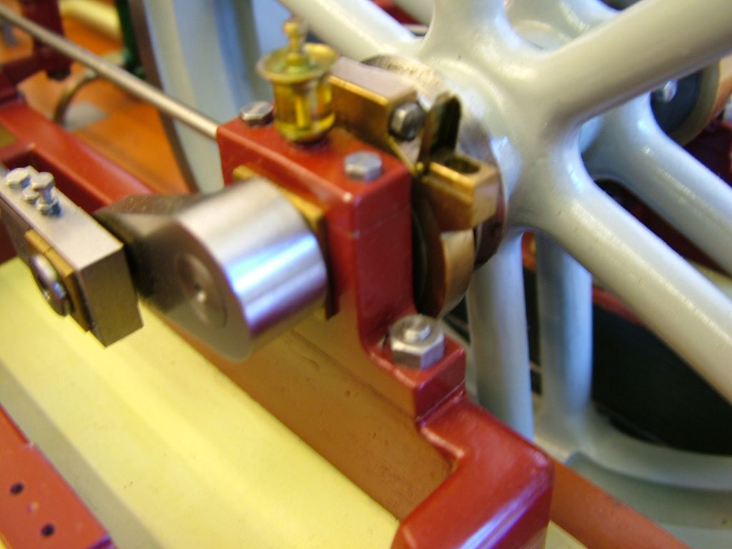
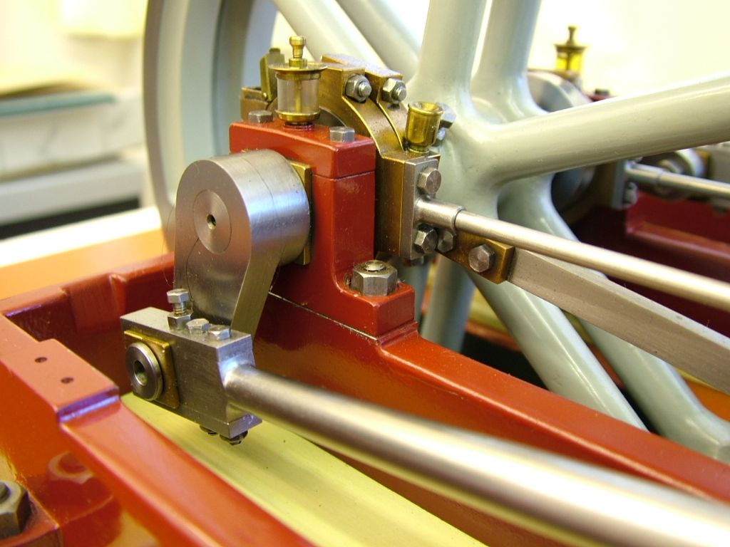
        Much easier to make two pedestals and caps from scratch in mild steel or cast and then make split bearings to suit, fundamentally as described above. I have quite a few images covering the latter from a previous thread if you want

        Here's my version on the Twin Vicdscf0421.jpg

        dscf0435.jpg

        #605683
        Dr_GMJN
        Participant
          @dr_gmjn
          Posted by JasonB on 13/07/2022 17:09:35:

          Put them in a cupboard and start from scratch, those look to be 7/8" ctr height ones not 5/8" that you want. It will be easier than trying to cut down and reassemble what you have.


          Thanks Jason – That's strange, the M.E. article says they come as castings, so I ordered the Twin Victoria Castings assuming they were referring to the kit castings (each bearing is listed as two part numbers)?

          I guess the new cylinder feet must be lower than the original, but how are you supposed to make the original castings work? Or are there 5/8" versions available for another model and I missed it in the article?

          Could I make them from solid brass, but keep the upper shells – I'd like to keep the pads for the oilers (and at least use something of the castings I bought)?

          Cheers.


          ETA – the cap bosses are actually slightly larger than the lower pedestals, and they will clean up to the correct width. It's just the lowers that are too narrow to clean up. Odd.

          Edited By Dr_GMJN on 13/07/2022 17:49:59

          #605685
          Dr_GMJN
          Participant
            @dr_gmjn
            Posted by Ramon Wilson on 13/07/2022 17:27:10:

            Posted by JasonB on 13/07/2022 17:09:35:

            Put them in a cupboard and start from scratch, those look to be 7/8" ctr height ones not 5/8" that you want. It will be easier than trying to cut down and reassemble what you have.

            Well yes, can't disagree with that but you did ask about the castings!

            Much easier to make two pedestals and caps from scratch in mild steel or cast and then make split bearings to suit, fundamentally as described above. I have quite a few images covering the latter from a previous thread if you want

            Here's my version on the Twin Vicdscf0421.jpg

            dscf0435.jpg

            Thanks Ramon, but I'm confused – if that's a Twin Victoria, how come it's got what look like 5/8" centre height pedestals combined with what look like the original kit cylinder mounts?

            Or are they 7/8" centre height? The Stuart Models TV instructions say they're 7/8" – the ones I've got – as Jason said…

            #605690
            JasonB
            Moderator
              @jasonb

              There was a thread about 18months ago discussing the different Victoria Drawings, early ones seemed to use the same castings as the beam engines beam pivot which need to sit highter at 7/8" which puts the crankshaft above cylinder ctr height. I think this is where the overlong conrod comes from too – a tough of copy and paste by the tracer! Later drawings and Andrew Smiths book have the bearings as 5/8".

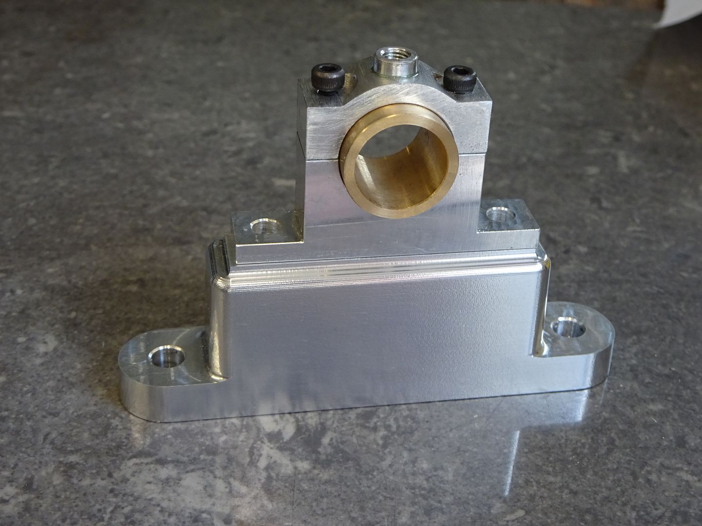
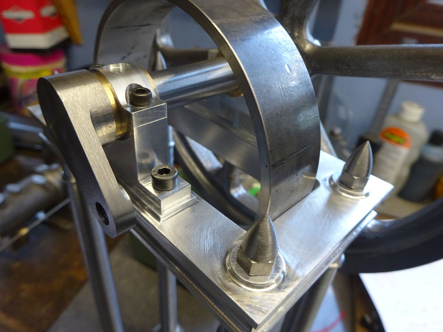
              That is not the only problem when I did the Victoria last year it came with bearings that had been started but unless you like your nuts hanging over the edge then the Stuart cap stud ctrs don't work too well either so I made mine from 3/8" aluminium with separate bearings turned from bronze. Likewise the recent Unreal which has a few photos and description.

              Victoria prior to easing corners and filleting, parallel bearing allows sideways adjustment if needed but were forced on my by an oversize 1/2" crankshaft

              Similar state of play on the Unreal but I used flanged bearings on that

              Overhanding caps would also look the part on what is now a model of a much larger prototype. Integral oil box as these or boss for screw in one


              Edited By JasonB on 13/07/2022 18:34:26

              Edited By JasonB on 13/07/2022 18:40:41

              #605693
              Clive Brown 1
              Participant
                @clivebrown1

                I made the Victoria last year, using drawings dated 1993 and after posting on this forum. As Jason says, there are a few inconsistencies with dimensions. The crankshaft is pitched 1/4" above the cylinder, that will work if you so choose but, IIRC, the con-rod length is wrong together with the positions of the slide bars along the bed.

                To save wasted work don't just make components to drawing and expect them to fit. It's best to measure carefully as you go along, and adjust dimensions to suit.

                #605699
                JasonB
                Moderator
                  @jasonb

                  Compromise might be to machine the half round bosses off all castings, chop an extra 1/4" off the pedestals to bring the ctr height down to 5/8". Bore 1/2" and fit separate bearings with 5/8" dia flanges but probably easier to start with a bit of spare ali that you may have from doing the bed castings.

                  If you do go for this option then the soft GM needs sharp cutters

                  Edited By JasonB on 13/07/2022 19:41:04

                  #605711
                  Ramon Wilson
                  Participant
                    @ramonwilson3

                    Doc, I made my Twin Vic many years ago. Apart from a small twin oscillator it was my first engine built and successfully finished – the first, a ST Compound Launch engine, was doomed from the outset due to lack of knowledge and skill at the time.

                    The exact date I'm unsure of but I do know I bought basic Twin Vic castings along with the drawing (which I still have somewhere I think ) when Stuart Turner traded from Henley and before they had the big hike in prices. Late seventies/early eighties perhaps?

                    I only bought the minimum of cast iron parts and not all of them at that – as best I can recall just the bed plates, cylinder blocks, piston rod end cover and valve chest and of course two flywheels. Everything else was made from scratch including those bearing pedestals which I'm pretty sure I made from mild steel. The bearings were from bronze and split. I always thought that the bearing housing make up was too 'thin' and were I to do another would bond on a plate to the sides of the bed plates to increase the potential width to mount wider bearing housings. I have no recollection of changing the design height of the bearing.

                    The original model engine was based on a quite small industrial engine that was found in an old premises I believe. Stuarts twin version was their idea of a potential engine that may have been offered by the manufacturer. Indeed quite a few did do this and I have a few reprints of old catalogues that support this possibility.

                    To use the parts to make a representation of a larger, heavier (full size) engine however there are areas that have to be improved not least in stature – the bearing supports are one. I often looked at the engine in hindsight and wished I had done that.

                    I've already mentioned to you the flywheel grooves – if done to print they are well over size for the size of engine but if done smaller and too many are put in then you increase the scale proportionally to the rest of the engine too – the engine becomes much larger and some areas are then truly undersized.

                    As Jason suggests, personally I would write the castings off at this stage – keep them for something else perhaps. Make new pedestals/housings from mild steel or the bit of cast you have left from the covers and make the bearings from bronze – even brass will do but bronze would be better. Using the yellow coloured cast bronze and not the pinkish drawn bronze will ease manufacture considerably.

                    Without looking I'm not sure what those drawings say about the crank relationship but I know I initially made it with the cranks at 180 degrees. Why I do not recall. When I first exhibited it at the Forncett Industrial steam museum however the owner commented on that irregularity immediately. Suitably chastised, once home it was immediately stripped it down and the crank shaft changed to the correct 90 degree relationship.

                    In the builds since that time then I have tried to incorporate full size characteristics where possible.

                    Hope that helps ease the confusion

                    Regards – Ramon

                    Edited By Ramon Wilson on 13/07/2022 21:36:05

                    Edited By Ramon Wilson on 13/07/2022 21:36:19

                    #605713
                    JasonB
                    Moderator
                      @jasonb

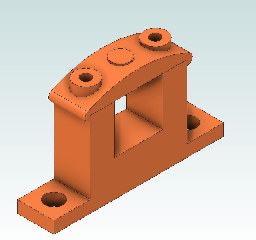
                      Great Minds Ramon, I posted this in Docs earlier thread before the build started which you may not have seen and is my thoughts for a twin Vicky with the heavier bearings. Think I also suggested bare minimum castings too.

                      twin vickys.jpg

                      #605720
                      Ramon Wilson
                      Participant
                        @ramonwilson3

                        No, that's new to me Jason but yes just the kind of mod I had in mind. I often wished that I'd also taken the time to make the cylinders with feet rather than the original method too – agh, hindsight is twenty twenty vision don't they say?

                        Just a thought Doc but somewhere I'm pretty certain I still have the form tools I made for the cross head spacers – HSS and form ground they're yours if you'd like them.dscf0434.jpg

                        #605729
                        Dr_GMJN
                        Participant
                          @dr_gmjn

                          Thanks all – give me some time to digest all that. I’ve been helping my son with his R/C car this evening…

                          #605820
                          Dr_GMJN
                          Participant
                            @dr_gmjn

                            OK, so I looked back at this thread, and noticed that for some reason I’d done some CAD for the crank height/cylinder height/cross-head bar length etc, (page 3), and confirmed that were all good, but found the clash between the connecting rod arm and the bed plate – this is why I made the beds longer, and reduced the height and location of the cross pieces.

                            So I’m fairly confident the connecting rod length is ok as per the P.R. article plans.

                            I also began this project with a separate thread on the Twin Victoria, and modifications that could be made to make it more realistic. I think I opted to build the P.R. based on an idea in that thread. I didn’t want to deviate from the plans too much, since it’s only my second model, hence one of the reasons for sticking with the original bearing widths.

                            Which brings me to those. I do have some bedplate aluminium left, and can get two pedestals out of them quite easily. I would like to retain the cast caps, perhaps modifying the stud size and spacing.

                            Could you give a process for making these? Jason – I looked at your Real thread, and saw you’d not split the bush – I would like to split it. I’d also remove the original cap cast bosses as suggested, and make the new double flanged shaped bushes to the correct width (not possible with the original cast lowers as mentioned)

                            I would like to paint the aluminium lowers, and the cast cap, but would leave the bush flanges natural metal.

                            Thanks.

                            #605824
                            Ramon Wilson
                            Participant
                              @ramonwilson3

                              Ali will be just fine Doc but some would say it's not a good combination with brass. Personally I'd go with it.

                              Re making the 'brasses' – I have several images of the process so will post them a bit later for you – just been called for my evening meal – daren't be late for that eh!

                              Back in a bit

                              #605835
                              JasonB
                              Moderator
                                @jasonb

                                I think I may have some old caps in the workshop so will mock up and take a few pics in the morning of how I would do the pedestal and cap, Ramon has covered split bearings well in the past so I'll leave that to him.

                                I do make split ones most of the time but on some of the small engines don't always bother to unsolder them if it is not required for assembly as it's easier to keep track of each pair. The Unreal id did as solid as my engines don't get the use to ever need wear taking up.

                                #605841
                                Ramon Wilson
                                Participant
                                  @ramonwilson3

                                  Hi again Doc,

                                  I have just created a new album with a series of images for making split bearings in my albums but will post a few? of the basic ones on here as it's relevant to your question – hope that's okay.

                                  You can make split circular bearings but these would not be true to prototype on the size of bearing you wish to represent. Split rectangular bearings are not exactly scale either but are much closer!


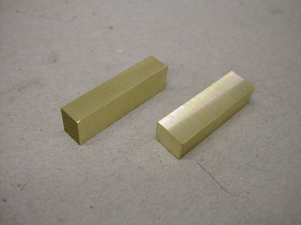
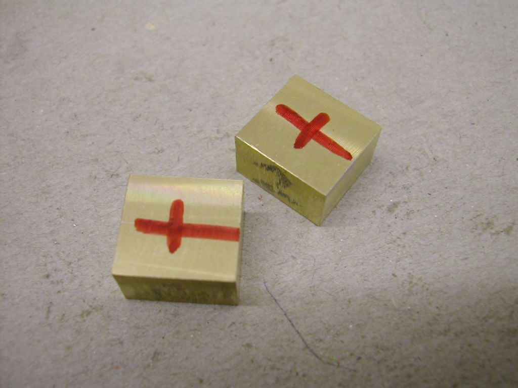
                                  Once you have established the dimension you require cut and mill two blocks to overall dimension plus 1mm and long enough to cut into two to give top and bottom pieces

                                  dscn3712.jpg


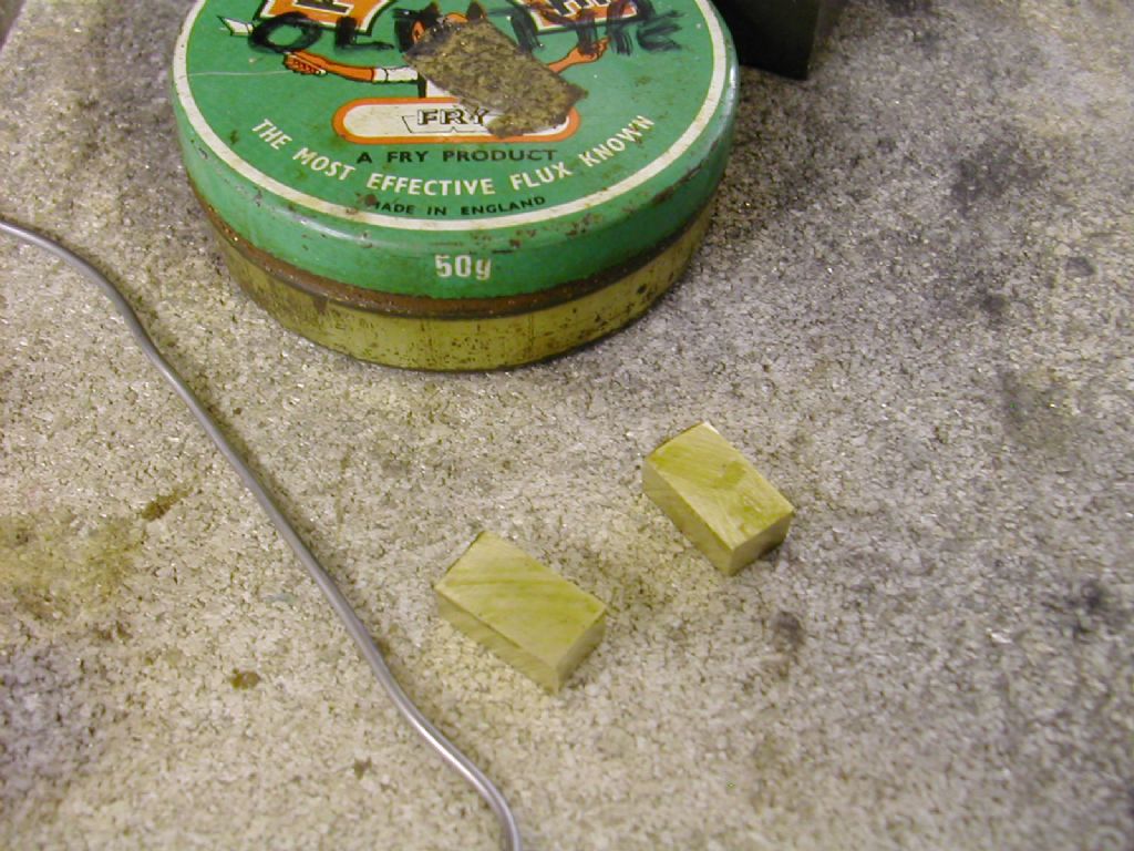
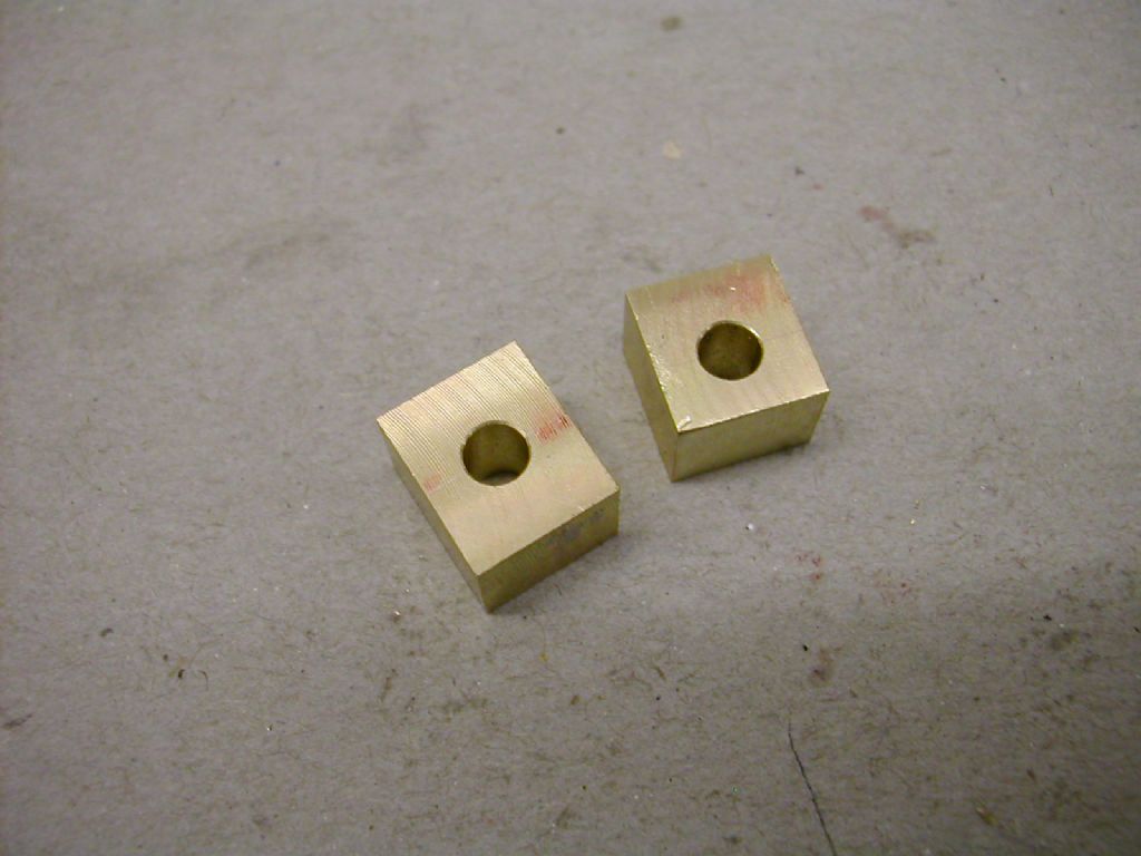
                                  Cut apart and face the sawn edges but do not worry about exact dimension at this stage. Make all blocks the same or at least the two lower blocks and note down the dimension from the split face to the lower surface . Then tin both parts on the split line face ready to solder together.

                                  dscn3718.jpg


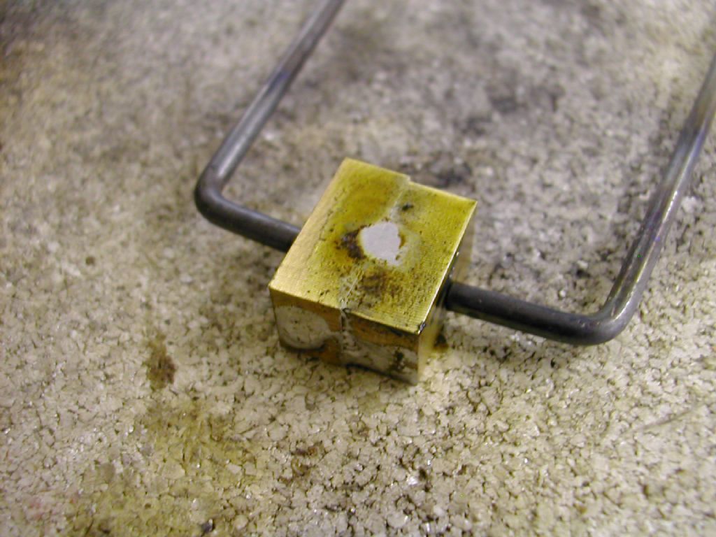
                                  The parts need to be held together but not clamped. I use a spring clamp made from a piece of 12 swg piano wire. Lay the parts on something flat that will not absorb too much heat and make sure the flat plane is uniform. Heat until you see the solder line go bright and drop a small amount of solder on to be certain.

                                  dscn3727.jpg


                                  Clean the blocks of flux then mill the outsides true except the lower face. From this you know exactly where the split line is located so set in the mill and drill bore etc for the crankshaft.dscn3744.jpg


                                  dscn3745.jpg


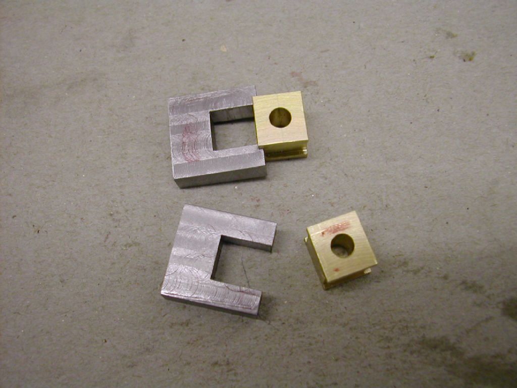
                                  Mill the outsides dimensions to the bore so they fit the pedestals

                                  dscn3749.jpg


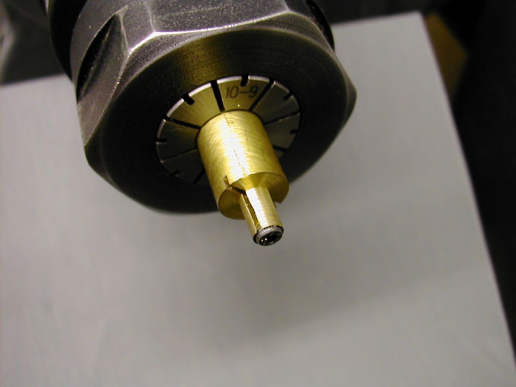
                                  Then finally make up a simple expanding mandrel to hold them for facing the outsides. This is quite a small one as these bearings were for the layshaft on the Waller valve gear but the principle is the same

                                  dscn3756.jpg

                                  dscn3762.jpg


                                  As said there are more images in the album which should be self explanatory but if you're not sure about something just say.


                                  Hope that helps – R


                                  Edited By Ramon Wilson on 14/07/2022 20:58:37

                                  #605845
                                  JasonB
                                  Moderator
                                    @jasonb

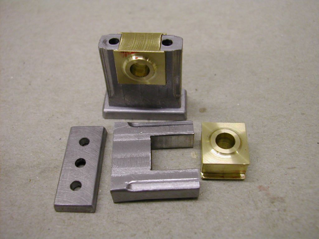
                                    You could actually make use of the lower castings if you went with a square bearing as the "cut" is higher up so the extra 1/4" you have to play with would be just right. Then either a simple rectangular cap like on Ramon's engine or you could get the rotary table out for something in keeping with an engine of this size.

                                    What size did you tap the bed casting, hopefully not the rather large 2BA.

                                    sq bearing.jpg

                                    Edited By JasonB on 14/07/2022 21:30:53

                                    #605854
                                    Dr_GMJN
                                    Participant
                                      @dr_gmjn

                                      Ramon, Jason; thanks for the suggestions and methods. Again, I’ll take some time to digest the information.

                                      Jason – the holes in the bed I made 3BA. Any bigger and the washers would overlap the edges. The plans show the mounts being slotted for adjustment, so I think I made them 3BA to enable washers to be used:

                                      I did half consider tonight making a saddle piece profiled to fit exactly over the bed sides, so I could make wider bearings as per your CAD, but my mounting lug is in the way. I will keep them as they are, because I put a lot of work into the beds to make them look nice and get accurate pad heights etc. Plus I want to make progress rather than re-work something that’s already complete. Next time though, with more experience I will consider things like this more carefully.

                                      Ramon – thanks for the offer of the form tool. I was hoping to try my hand at making my own, particularly for oil cups. A ‘how to’ for form tools in terms of techniques and equipment would be appreciated. I also need to make a simple radiussed tool for the connecting rod end blend radii IIRC.

                                      Thanks.

                                      #605856
                                      Dr_GMJN
                                      Participant
                                        @dr_gmjn

                                        …I suppose looking at it again I could make the pads wider by locally making the outer sides vertical rather than angled, but…is it worth it? I think I’ll stick with them as they are.

                                        #605865
                                        JasonB
                                        Moderator
                                          @jasonb

                                          Probably not worth altering now as you would also need to fill and reposition the holes. I must have said earlier about fixing size, 3BA or M4 is a better fit and look.

                                          #605868
                                          Ramon Wilson
                                          Participant
                                            @ramonwilson3

                                            I would agree with you to leave the bed plates as is now but go ahead with scratch built bearing housings and bearings.

                                            I have found the form tools – two pieces of 1/4 square HSS – I note the form was ground in with a true radius so this dates my build around 1983/4 as they were done on a J&S grinder with 'Optidress' wheel dressing/shaping kit. Must have been one of my first 'homers' at a company I joined in 84 !!

                                            Making external form tools from HSS is usually a carefully approached attempt on an offhand grinder – use those small bits I sent you so there's not so much grinding. Internal forms (in HSS) are a different matter without recourse to some special kit so it's then down to creating the shape in tool steel – usually silver steel or gauge-plate for instance – my machining/filing before heat treating. I always quench in oil and if it's a small tool for just doing half a dozen oil cups for instance very rarely bother to temper but keep the maximum hardness. Sharpening is best carried out using a diamond file – hand grinding on the offhand grinder will quickly lose the hardness without extreme care.

                                            Have to go now – breakfast calls.


                                            PS PM your address

                                            Edited By Ramon Wilson on 15/07/2022 07:47:35

                                            #605871
                                            Dr_GMJN
                                            Participant
                                              @dr_gmjn

                                              Thanks both for the info. As I mentioned, I’d like to stick to the look of the article model, and keep at least some of the bearing castings (ie the uppers), so ideally I’d have circular split bosses rather than square.

                                              Could you outline how to make these, is it a question of turning oversized flanged bushes, splitting them, then JBWelding them into the bearing castings, then re-joining and boring?

                                              Ramon – I don’t have a boring head for the mill, but you’re saying the housings aren’t strong enough to be clamped in the 4-jaw chuck? I machined the 10V big end in the chuck, but it was a bit smaller/stiffer I guess.

                                              Cheers.

                                              #605879
                                              Dr_GMJN
                                              Participant
                                                @dr_gmjn
                                                Posted by JasonB on 15/07/2022 06:56:17:

                                                Probably not worth altering now as you would also need to fill and reposition the holes. I must have said earlier about fixing size, 3BA or M4 is a better fit and look.

                                                Jason, the P.R. Plans call for 3BA, so I probably just followed them.

                                                Perhaps the best option would be to get some brass or gunmetal blocks from my local supplier, and just replicate the originals, but shorter. I guess it would make everything simpler?

                                                #605884
                                                JasonB
                                                Moderator
                                                  @jasonb

                                                  I think using some spare 3/8" aluminium for both parts is probably the best option as it saves having to form the hole in two separate metals which the problems of drift that can cause. As you are likely to end up wanting to machine the whole of the cap anyway there is little reason to use the casting and working with rectangular blocks to start will will make critical machining easier then the fancy shaping can follow.

                                                  What do you have in the way of bronze in stock, round or square/rectangular?

                                                  Also do you have a 1/2" milling cutter or reamer?

                                                  Edited By JasonB on 15/07/2022 09:42:48

                                                  #605895
                                                  Ramon Wilson
                                                  Participant
                                                    @ramonwilson3

                                                    Posted by Dr_GMJN on 15/07/2022 08:13:44:

                                                    Thanks both for the info. As I mentioned, I’d like to stick to the look of the article model, and keep at least some of the bearing castings (ie the uppers), so ideally I’d have circular split bosses rather than square.

                                                    Could you outline how to make these, is it a question of turning oversized flanged bushes, splitting them, then JBWelding them into the bearing castings, then re-joining and boring?

                                                    Ramon – I don’t have a boring head for the mill, but you’re saying the housings aren’t strong enough to be clamped in the 4-jaw chuck? I machined the 10V big end in the chuck, but it was a bit smaller/stiffer I guess.

                                                    Cheers.

                                                    Hi Doc,

                                                    No, I'm not saying they can't be done using a four jaw chuck just that the material is easy to distort. If you apply sufficient pressure to hold the part for boring there is a good possibility the pressure of the jaws distorting the thinner walls left. My reasoning is simple, why go there in the first place and risk it – if you machine everything to the bore then that potential is irrelevant.

                                                    Doing circular bearings is exactly the same – solder two pieces together and hold on a mandrel – the difficulty is finding the exact centre line from semi circular pieces (if you go that way – just easier and far more accurate to make them square in the first place).

                                                    Again, not saying it can't be done just much easier to get the right end result with square bearings which as said are far more true to prototype than circular – on main bearings that is.

                                                    This is a pretty simple part to manufacture from scratch – I can understand the desire to use the original castings but to try to compromise is not ideal – as ever "one pays one's money" etc

                                                    I have plenty of bronze so can send you some with the form tools – just let me know the overall dimensions you need.

                                                    #605911
                                                    JasonB
                                                    Moderator
                                                      @jasonb

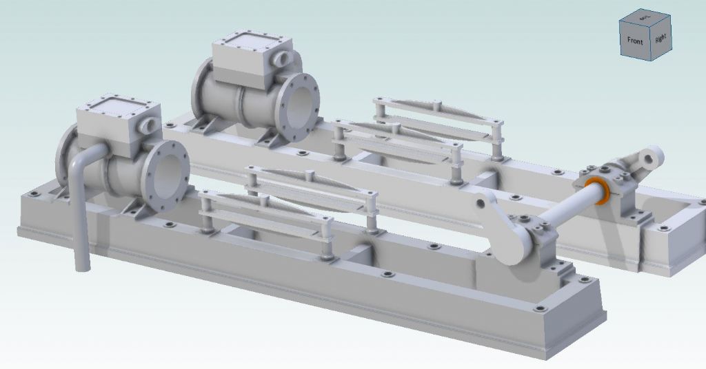
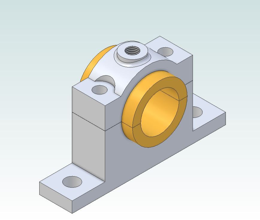
                                                      This is the Princess one Modelled and shown with separate split round bearings. Let us know which way you want to go with final shape and preferably all new material before We spend time describing other options.

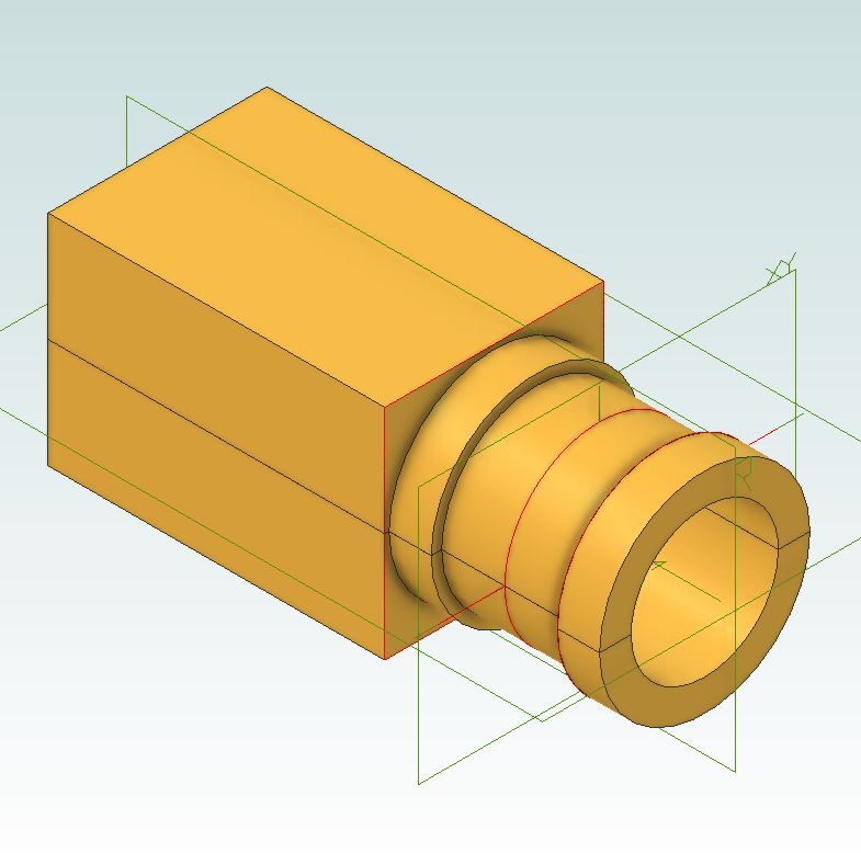
                                                      I've also added an image to show how the bearings can be turned from two rectangular sections soldered together, length enough for two plus something to hold.

                                                      princess bearing.jpg


                                                      princess stock.jpg

                                                      Edited By JasonB on 15/07/2022 11:01:16

                                                    Viewing 25 posts - 601 through 625 (of 1,262 total)
                                                    • Please log in to reply to this topic. Registering is free and easy using the links on the menu at the top of this page.

                                                    Advert

                                                    Latest Replies

                                                    Viewing 25 topics - 1 through 25 (of 25 total)
                                                    Viewing 25 topics - 1 through 25 (of 25 total)

                                                    View full reply list.

                                                    Advert

                                                    Newsletter Sign-up