Stiffness for an indicator mount

Stiffness for an indicator mount

Home Forums Beginners questions Stiffness for an indicator mount

Viewing 25 posts - 1 through 25 (of 30 total)
  • Author
    Posts
  • #265364
    Iain Downs
    Participant
      @iaindowns78295

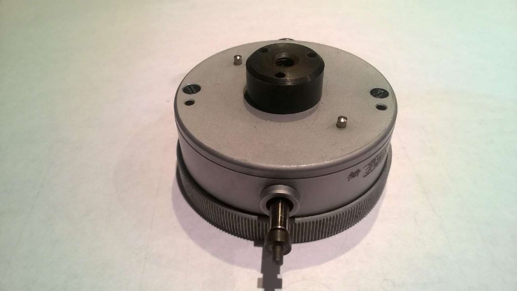
      I've acquired a Geneve Micron indicator from the auction-site-which-may-not-be-named.

      geneve micron indicator.jpg

      My other indicators have various mounting lugs non of which are like the above. So I want to create a mount which will take a 6×8 bar from my height gauge or a 10mm rod from a standard magnetic mount.

      My problem (if it is a problem) is that this thing is heavy. It weights 250gms – half a pound in old money.

      I'm thinking I can make the mount in aluminium or steel. Essentially, I'll take a cylinder about 50mm in diameter and 15mm deep and bore recesses and cut holes as appropriate.

      If I make it in steel it will be heavy which may cause droop on whatever it is mounted on. If I make it in ally it will be much lighter, but will it be stiff enough to support the indicator in rods and bars?

      Or am I worrying over nothing?

      I can ameliorate the steel weight by milling out the areas around the holes and so on, but this in turn may reduce the stiffness – and will double the time to make the thing.

      Your usual excellent (and sometimes unexpected) advice is antipated!

      Iain

      #8373
      Iain Downs
      Participant
        @iaindowns78295
        #265368
        Martin Connelly
        Participant
          @martinconnelly55370

          Stiffness is largely a function of diameter (that's why scaffold poles are tubes not bars) so you get the same stiffness for less weight from a piece of pipe. Try to design something with the core removed or from suitably sized pipe.

          Martin

          #265369
          David Colwill
          Participant
            @davidcolwill19261

            Hi Iain,

            You may want to watch this video by the excellent Stefan Gotteswinter on indicator sag.

            Here is a link **LINK**

            I think the aluminium version would be fine but perhaps a steel sleeve to attach the rod.

            Regards.

            David

            #265375
            mechman48
            Participant
              @mechman48

              …. I've acquired a Geneve Micron indicator from the auction-site-which-may-not-be-named…

              Why?… eBay…it's a global public auction/selling/buying site with no copyright restrictions that I know of, we've all bought / sold stuff from / on it at one time or other… same with the other site…'Gum tree'… just name it! you won't be castigated for it.

              George.

              #265385
              jason udall
              Participant
                @jasonudall57142

                If being used as a “comparitor”.

                The droop will remain the same, and hence irrelevant, if the measurement “force” remains the same.
                Careful design of the clock will mitigate the variation of force with measurement displacement. .
                That aside stiffness or rather lack of stiffness will frustrate you evey time you use it.

                I second the tube solution..maybe with rod under tension down core

                #265388
                Ajohnw
                Participant
                  @ajohnw51620

                  The stands on the dti holders for use on a surface plate are more rigid than the typical type used on a lathe. One I have for instance has a 7/8" dia vertical pole and the articulated one is 5/8" dia.

                  That was probably intended to allow accurate comparison using a 1/10,000" dti.

                  John

                  #265389
                  jason udall
                  Participant
                    @jasonudall57142

                    Arr..re read the op.

                    You already have the arm..you are just about the coupling.

                    #265411
                    Ajohnw
                    Participant
                      @ajohnw51620
                      Posted by jason udall on 08/11/2016 10:04:00:
                      Arr..re read the op.

                      You already have the arm..you are just about the coupling.

                      Just passing on some manufacturer's idea of adequate stiffness Jason,

                      John

                      #265449
                      Michael Gilligan
                      Participant
                        @michaelgilligan61133

                        Iain,

                        1. I'm very envious … wish I had seen that one.
                        2. Martin's remark about scaffold poles is spot-on [whether we are talking about arms, or brackets], but I would just add that circular cross-section is not necessarily optimum … if the loading is predominantly in one direction, then a 'deep' rectangular box-section may be more appropriate.
                        3. Yes: This indicator is unusually heavy, and minimising the incremental increase in weight will be advantageous … provided you can retain the necessary stiffness.
                        4. 'Stiffness to Weight Ratio' is what really matters here; and that can be varied by choice of shape or choice of material. Choice of shape has already been mentioned [and in-extremis, leads us to the monocoque shell] … Choice of material is interesting, in that most engineering materials will be found to have similar 'Stiffness to Weight Ratios' [so, a very thin steel shell weighs approximately the same as the thicker aluminium alloy shell of comparable stiffness] … Exotic materials such as titanium, and carbon fibre composites break out of this trap.
                        5. Using this as a 'general purpose' indicator would be [as my friends in Liverpool used to say] "like using a Rolls Royce to kill a Pig" … effective, but rather too good for the job! … Find a task that is worthy of it, and design your supporting bracket accordingly.

                        Sorry to witter-on … hopefully there is something of interest there.

                        MichaelG.

                        #265507
                        Howard Lewis
                        Participant
                          @howardlewis46836

                          Are there two tapped holes in the back?

                          If so, why not make up a plate with dowel holes to match the two dowels, and fix to to the form of adaptor, (1/4" dia?) to fit into the monkey block on your mag base?

                          Yes, keep it as light as possible, but not so thin that it flexes, (1/4"/6mm gauge plate springs to mind) with the adaptor bar screwed into the edge.

                          If it measures in microns, everything needs to be secure, but don't spend too long breathing on the set up or thermal expansion will become noticeable.

                          Howard

                          #265527
                          Iain Downs
                          Participant
                            @iaindowns78295

                            I'll double check for tapped holes, but I don't think so.The main fixing appears to be an M5 bolt going into the centre round lug. If there are it would make the task easier

                            I'm intending to use if for surface plate measurements not lathe measurements. If I got within a though on my lathe I would be ecstatic!

                            Tasks that are in it;s near future include checking out my surface plate (which appears to be a few tenths in one quadrant), getting the to flat of my prism spot on parallel with the base and flattening a piece of plate glass a bought to act as a lapping plate only to discover that optically good and flat are different things.

                            I can probably get the weight of a steel mount down to 150gms and an ally version down to 70 gms maybe?

                            Oh = there seems to be a tradition on not naming ebay in posts. I don't know why. I was being ironic…

                            I'll post a picture when I'm finished (which will likely not be soon)

                            Thanks

                            Iain

                            #265569
                            jason udall
                            Participant
                              @jasonudall57142

                              Just for info

                              The TESSA height gauge I used sensed the force ( strain gauges) of contact and recorded the “height” ( actually it also had a second axis but enough about that)..at a consistent contact force.
                              This in effect nulls out any bendyness in the system..probe..column etc.
                              The whole thing run on a air film for positioning then lands to measure…
                              Lovely instrument. .used to 0.1micro meter. .I always wondered just how much effect any “lean” of the part might have…

                              Edited By jason udall on 09/11/2016 09:11:43

                              #265578
                              Ajohnw
                              Participant
                                @ajohnw51620

                                Not sure if it's of interest but there is a surface plate DTI base on ebay at the moment, 391426886831. A bit smaller than mine but should be adequate. Looks like it has it's own test bad as well. The dti would normally be sticking out the other way so they need to be heavy.

                                Surface plates are like anything else. They have a tolerance. It's usually possible to null the error out by reversing "the part" and seeing if the error in the part is still the same. Engineering optical flats are usually to a 1/4 wave. Optical vary. For glass you might find 25mm glass is better. Disks can be bought that are used to make telescope mirrors that have been cut from 25mm plate. Moulded ones are best avoided.

                                If you buy 3 telescope mirror blanks it's possible to make your own optical flat by testing on against another and using some simple algebra. Details are in some of the telescope making books. If the blank is 25mm thick I'd guess that the max dia to hold optical flatness levels would be 150mm.

                                One source of blanks is this one. You could ask how flat is flat. There are other sources even a couple in the UK.

                                **LINK**

                                The ground finish he supplies is pretty matte.

                                John

                                 
                                #265596
                                Dinosaur Engineer
                                Participant
                                  @dinosaurengineer

                                  The stiffness of a round bar is proportional to the 4th power of its diameter. Thus if a bar diameter is increased by a factor of 2 then the stiffness is increased by a factor of 16. ( 2 to the power of 4). This should be born in mind when choosing boring bars as well as indicator bars. But of course the weight of a solid bar also increases proportional to its radius squared. The weight can be reduced by using hollow tubes instead of solid bars.

                                  #265655
                                  Iain Downs
                                  Participant
                                    @iaindowns78295

                                    Hey, John.

                                    Thanks for the link. I'm looking to make my own base, though this thread has made me think more broadly about what I want rather than the bits individually.

                                    I bought a 600 x 450 glass plate to act as a lapping plate / surface plate on the expectation that it would be flat. It's not and the large scale tolerance for glass plate turns out to be quite large. It turns out the a colleague of mine is an ex glass QC manager… So I want to make use of something I've spent 50 quid on even at great personal effort. What? Who said, 'Yorkshireman'?

                                    The the link is useful and may fit into a mad idea of mine in future.

                                    Dinosaur – thanks for the info. I hadn't realised the ratio was so large.

                                    Iain

                                    #265723
                                    Michael Gilligan
                                    Participant
                                      @michaelgilligan61133
                                      Posted by Iain Downs on 09/11/2016 19:13:58:

                                      Dinosaur – thanks for the info. I hadn't realised the ratio was so large.

                                      .

                                      Iain,

                                      My apologies … When I posted on Tuesday, I had presumed a level of knowledge.

                                      A useful bit of 'armchair engineering' might be to read-up on 'moments of inertia' [forgive the inevitable pun] … Machinery's Handbook has some good illustrated tables, and I'm sure there are similar available on-line.

                                      MichaelG.

                                      #265841
                                      Iain Downs
                                      Participant
                                        @iaindowns78295

                                        HI, Michael.

                                        Erm. Are you Dinosaur?

                                        I don't quite understand your reference to moments of inertia (other of course than the reason we watched so much poor TV before remote controls…). Stiffness and moments of inertia are quite different.

                                        For the record, I'm pretty reasonable on physics (what stiffness and moments of inertia are), but I'm a damn poor engineer (the practical bits)!

                                        Iain

                                        #265853
                                        Michael Gilligan
                                        Participant
                                          @michaelgilligan61133
                                          Posted by Iain Downs on 10/11/2016 17:31:36:

                                          HI, Michael.

                                          Erm. Are you Dinosaur?

                                          .

                                          No, Iain … and apologies to either or both of you if I have caused any offence by quoting your reply.

                                          MichaelG.

                                          #265930
                                          Roger Head
                                          Participant
                                            @rogerhead16992
                                            Posted by Iain Downs on 10/11/2016 17:31:36:

                                            HI, Michael.

                                            … Stiffness and moments of inertia are quite different.

                                            Iain

                                            Iain, in the context of the thread, I think Michael's suggestion of 'armchair engineering' reading was quite reasonable. Certainly E and I are different, but E is simply a material property and having selected your preferred material it will then be I that determines how 'stiff' your structure is (i.e. what the effective 'E' of your structure is).

                                            But I suspect you already know that…

                                            Roger

                                            #266055
                                            Iain Downs
                                            Participant
                                              @iaindowns78295

                                              I got a bit confused by the last few posts, but no matter – I've got a lot out of this thread.

                                              I'd assumed that the force to displace the indicator needle was small compared to the weight of the indicator. This appears to be wrong. if I hold the indicator above a scale (kitchen) it doesn't really start to read until the scale shows 100 g and that rises to nearly 200 gms and full displacement. The indicator scale covers 5mm but the actual displacement range is nearer 10.

                                              So the effective downward force could vary by a considerable amount. Obviously, if I'm comparing one height which 10 microns different to another this is not going to matter, but over a couple of mm it's important.

                                              So if I want to compare heights of the order of mm I need a much stiffer mount and base than over microns.

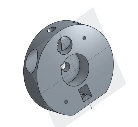
                                              The mount I hand in mind looks like this

                                              mount.jpg

                                              What's changed in my thinking is what that attaches to. One thing I want to do is to check the parallelism of my prism. For that I will make a stand that this bolts to and is a decent piece of steel down to a solid base. it will measure relative heights but only one or two centimetres away from an edge.

                                              In the diagram above I can attach to the 6×8 arm of my height gauge or a 10mm round bar from an indicator base. Fine I think for things like clocking a surface plate assuming it is reasonably close to spec.

                                              I need to think about balance though and might need a counter-balance on the other side of the base if I am looking at much more than 10cm.

                                              Iain

                                              #266073
                                              SillyOldDuffer
                                              Moderator
                                                @sillyoldduffer

                                                Posted by Iain Downs on 11/11/2016 18:25:59:

                                                I'd assumed that the force to displace the indicator needle was small compared to the weight of the indicator. This appears to be wrong. if I hold the indicator above a scale (kitchen) it doesn't really start to read until the scale shows 100 g and that rises to nearly 200 gms and full displacement.

                                                Iain

                                                Hey that's interesting!

                                                Wouldn't measuring anything remotely bendy (like a rod supported at one end in a chuck) be rendered inaccurate by an instrument needing that level of force to get a reading?

                                                Ta

                                                Dave

                                                #266075
                                                jason udall
                                                Participant
                                                  @jasonudall57142

                                                  Wouldn’t measuring anything remotely bendy…..

                                                  In my experience. .yep
                                                  There are many sources of error..a consideration of all of these needs to.be made.

                                                  #266087
                                                  SillyOldDuffer
                                                  Moderator
                                                    @sillyoldduffer
                                                    Posted by jason udall on 11/11/2016 20:42:35:
                                                    Wouldn't measuring anything remotely bendy…..

                                                    In my experience. .yep
                                                    There are many sources of error..a consideration of all of these needs to.be made.

                                                    Damn and blast it! Isn't anything ever easy?

                                                    #266100
                                                    Mark C
                                                    Participant
                                                      @markc

                                                      This sounds like we might be looking at Shrodinger's cat (pun intended).

                                                      Mark

                                                    Viewing 25 posts - 1 through 25 (of 30 total)
                                                    • Please log in to reply to this topic. Registering is free and easy using the links on the menu at the top of this page.

                                                    Latest Replies

                                                    Home Forums Beginners questions Topics

                                                    Viewing 25 topics - 1 through 25 (of 25 total)
                                                    Viewing 25 topics - 1 through 25 (of 25 total)

                                                    View full reply list.