Myford S7 Cutting Barrel Shaped Cylinders

Advert

Myford S7 Cutting Barrel Shaped Cylinders

Home Forums Workshop Tools and Tooling Myford S7 Cutting Barrel Shaped Cylinders

Viewing 25 posts - 76 through 100 (of 114 total)
  • Author
    Posts
  • #476255
    Hopper
    Participant
      @hopper

      I dont think the vertical wear on the top surface is as critical as you think, Martin. I can't quite visualise the amount of movement on a square/triangle as you describe. Besides, the tool point is not 3.5" from the rear shear. On a 1" diameter test piece it is only 1/2" from the spindle centre line, which on a Myford is offset toward the rear shear significantly for the specific purpose of giving good geometry under load on the front shear. So maybe more like 1.5" between rear shear pivot point and tool point. But also if the tool were moving outwards by the significant amount youi posit, the job would be turning larger toward the chuck, but as it is barrel shaped, it is getting smaller toward the chuck.

      Advert
      #476258
      Hopper
      Participant
        @hopper
        Posted by Mike Donnerstag on 30/05/2020 13:21:45:

        Hopper: I don’t know much about the use the machine had been put to prior to my owning it, but I think your suggestion of a previous owner threading using a die-holder would account for that bed wear.

        Measuring again, apart from the last 2 inches of the bed, the bed width across both shears shows no more than 1thou of wear (not bad at all!), according to my digital calipers (the only micrometer I have is 0-1&rdquo. This includes the visibly worn area on the top of the front shear. The final 2” measures 1.5-2thou above that, which accounts for my initial wear measurement of 3.5thou.

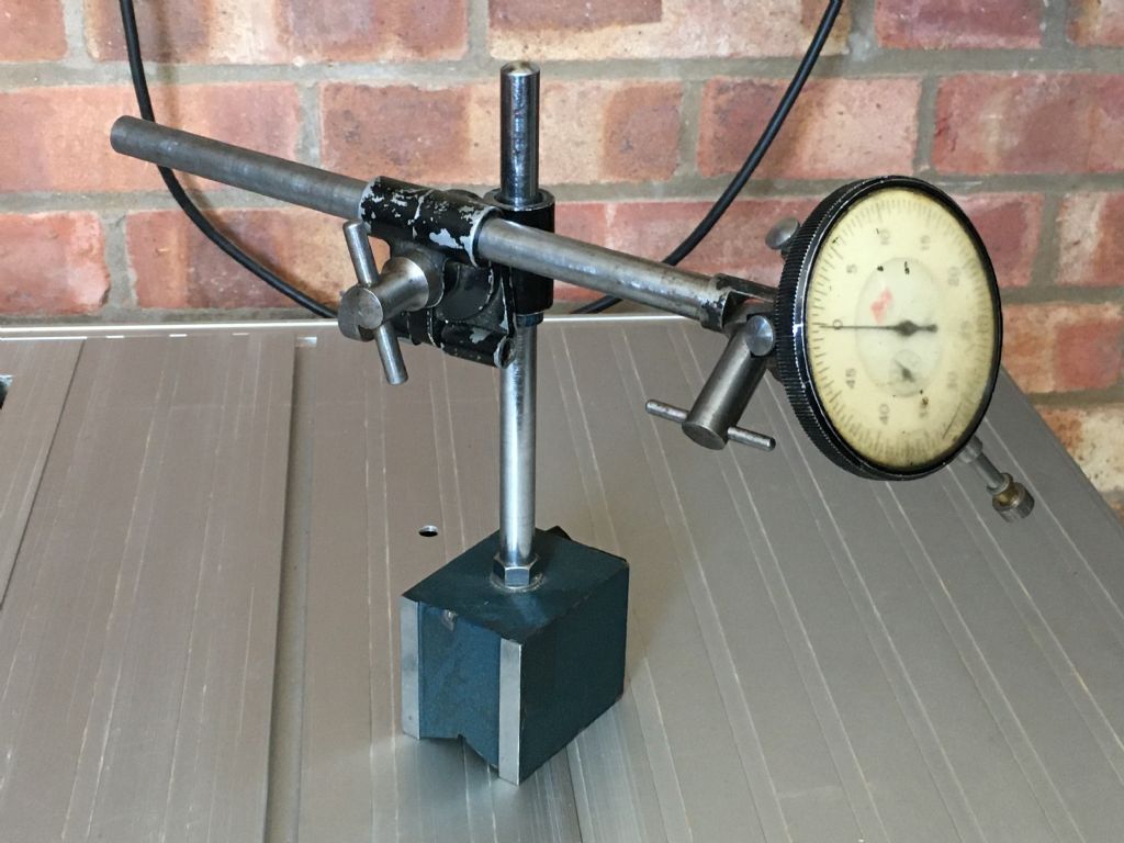
        Slightly off-topic, but where did you get your small red magnetic indicator stand?

        Or, is it an expensive Noga? My magnetic stand is quite large and the dial gauge on top is even larger. For that reason I tend to use a sensitive dial test indicator in the toolpost whenever possible, but I do need to buy a more compact magnetic stand to make setting up easier. My Batty in the magnetic stand is pictured below. I don't use it much as it's just too bulky and a pain to set up.

        magnetic stand and large clock.jpg

        Edited By Neil Wyatt on 30/05/2020 22:02:03

        Hi Mike

        The stand and the DTI are eBay cheapies. Seem to work just fine.

        Re your bed measurements above it sounds like that scarred up area is the cause? It would pay to measure the width of the back shear itself and try to determine how much wear is on that very rear guiding surface without interference from that scarred up front shear.

        Sounds like in the meantime you have the spindle movement in the ballpark. A little more than I would aim for but I think acceptable and almost certainly not enough to cause barrel shaped turning. No idea what the factory clearance spec is for the Super 7 oddball bearing set up. I aim for half a thou on plain bearings like the ML7 but I think your one thou or so should be passable.

        Did you run a flat file over that scarred up front shear to make sure there is no raised ridge of metal around its edges? Might be worth a try.

        Another thing you could try is setting up the lathe in the absence of expensive level by using the second method in the Myford owners manual that I described in a post above earlier, basically with a dial gauge on a long bar in the chuck to make sure no stress is put on the bed during bolting down.

        Yet another thing I would look at is how you are holding your test piece for turning. Your OP said you only had 1" held in the collet. I would like to see double that if I were doing it. In fact I would fit the four jaw chuck and hold the bar in that. Just to eliminate the possibility of some movement of the job in the collet under load in a job sticking out so far. Don't use your three jaw chuck for this test as it is quite possibly bell mouthed if in similar condition to that bed!

        #476277
        Mike Donnerstag
        Participant
          @mikedonnerstag

          Hopper: Instead of a flat file, I ran a small flat slipstone over the scarred-up front shear. So far at least, I don't think that area is to blame for the barrel shape, but I'll do some more testing today. I'm determined to get to the bottom of this and thank everyone who has posted so far for their help.

          Regarding the stress on the bed, one thing I intend to try is to see how the bed reacts when the nut pressure on the right hand end is released. I'm still wondering if the problem is a combination of headstock misalignment and bed compensation.

          Mike

          #476316
          blowlamp
          Participant
            @blowlamp

            One thing I forgot to mention is that the carriage gib strip should be fitted & adjusted correctly.

            It should be removed and checked to ensure it has a slight bow, such that it contacts the bed first in the middle. This is to ensure full contact along its length as it is adjusted and only needs to be of a few thousandths of an inch, but it isn't critical just as long as the bow is there and can be flattened back out by adjustment without causing the carriage to bind.

            If the centre of the gib strip isn't firmly touching, then when the saddle starts to become unsupported by moving over the gap in the bed, there might be a tendency for the cutting tool to deviate frome a straight line.

            Martin.

            #476398
            Graham Meek
            Participant
              @grahammeek88282

              Hi Martin,

              Your analogy concerning the rear bedway pivot point would be correct if the surface of the bedway was indeed flat between the two points. If they were I would be forced to agree with you.

              However having done several plots across the bedways given the bed wear shown in Mike's photograph the surface at each point approximates to a curve. The radius of this curve varies with the bed wear at each point of measurement. From my plots I get radii for the curvature ranging from 36 to 75 feet.

              The centres of these radius are below the bedway and their positions vary laterally with regard to the Spindle centre. As the centreline of the lathe is very approximately at the top of these radii, any vertical, or lateral movement is going to have very little effect on the workpiece. Working with these radii and a bit of Pythagoras I got an average for the figure mentioned above.

              Also as a point of interest. From the drawings on the S7 Screwcutting clutch I make the spindle centreline slightly less then 2" (50.27 mm) from the rear vertical face of the rear bedway.

              Regards

              Gray,

              #476406
              Martin Kyte
              Participant
                @martinkyte99762

                Hi Graham

                I don't doubt that the actual situation is more complicated that my two points. You have clearly done more work on this than me. It's anybodies guess as to areas of contact underneath the saddle. I think my conclusion at this point would be that the bed has had it and needs a regrind.

                I don't know idf the folowing test has been done but if a true test bar is put in the spindle or held between centres and the dial indicator is tracked down the bar noting readings and distance as you go if all else is correct apart from the bed and saddle that gives an absolute locus for the tool path.

                best regards Martin

                #476437
                Mike Donnerstag
                Participant
                  @mikedonnerstag

                  Blimey – I can hardly keep up with all the information! Many thanks everyone.

                  blowlamp: I can confirm that a turned bar is indeed round, definitely to within a tenth of a thou (0.0001), as measured by my Mitotoyo mic.

                  Although the above test has confirmed that the bearings are good, I've readjusted the front bearing (leaving the rear bearing preload alone) to be ever so slightly 'tighter'. I'll post the results of the spindle movement using a bar in a chuck as a lever as before.

                  #476471
                  blowlamp
                  Participant
                    @blowlamp
                    Posted by Mike Donnerstag on 31/05/2020 17:41:43:

                    Blimey – I can hardly keep up with all the information! Many thanks everyone.

                    blowlamp: I can confirm that a turned bar is indeed round, definitely to within a tenth of a thou (0.0001), as measured by my Mitotoyo mic.

                    Although the above test has confirmed that the bearings are good, I've readjusted the front bearing (leaving the rear bearing preload alone) to be ever so slightly 'tighter'. I'll post the results of the spindle movement using a bar in a chuck as a lever as before.

                    That's not a bad result at all.

                    Why not hold your test bar along each vertical shear and shine a light from below to check for worn areas?

                    If you can hold/secure it well enought, then you might be able to introduce a feeler gauge into any gap to measure the wear.

                    Martin.

                    #476834
                    Mike Donnerstag
                    Participant
                      @mikedonnerstag

                      To summarise the situation so far as I understand it…

                      1) The bearings have been adjusted according to the manual and Malcolm's notes. The lathe is cutting perfectly round, at least according to my vernier micrometer

                      2) The wear in the lathe bed alone is nowhere near enough to cause the extent of 'barrelling' that I am experiencing

                      3) This therefore points to lathe bed twist and/or headstock alignment

                      Having had inconsistent results doing a similar thing as before, but this time with a thicker bar held solidly in a four jaw chuck, I'm going to try measuring with my DTI and the precision ground test bar tomorrow.

                      Gray: I'll check the test bar for concentricity first, as you suggested. This is something I haven't done as yet.

                      I'll also try the 'Rollie's Dad's method' of removing twist from the lathe bed.

                      If the problem does point to the headstock being out of alignment with the bed, can this be adjusted without removing the gearbox or other ancilliaries?

                      Mike

                      #476846
                      blowlamp
                      Participant
                        @blowlamp
                        Posted by Mike Donnerstag on 01/06/2020 22:57:48:

                        To summarise the situation so far as I understand it…

                        1) The bearings have been adjusted according to the manual and Malcolm's notes. The lathe is cutting perfectly round, at least according to my vernier micrometer

                        2) The wear in the lathe bed alone is nowhere near enough to cause the extent of 'barrelling' that I am experiencing

                        3) This therefore points to lathe bed twist and/or headstock alignment

                        Having had inconsistent results doing a similar thing as before, but this time with a thicker bar held solidly in a four jaw chuck, I'm going to try measuring with my DTI and the precision ground test bar tomorrow.

                        Gray: I'll check the test bar for concentricity first, as you suggested. This is something I haven't done as yet.

                        I'll also try the 'Rollie's Dad's method' of removing twist from the lathe bed.

                        If the problem does point to the headstock being out of alignment with the bed, can this be adjusted without removing the gearbox or other ancilliaries?

                        Mike

                        A twisted bed or misaligned headstock should only cause a taper to be turned. I can't really see why it would make a part barrel shaped.

                        Did you see my post about setting up the carriage gib strip properly?

                        Martin.

                        #477052
                        Mike Donnerstag
                        Participant
                          @mikedonnerstag

                          Martin: I did see your post about the carriage gib strip. In fact, it prompted me to remove the leadscrew, saddle and apron again today in order to check. I found that the gib strip had a convex and a concave face and it was the concave face that was in contact with the bed. I notice that it can simply be reversed, so that’s what I’ll do when I reassemble.

                          Another reason I removed the apron is to replace the two bushes supporting the rack pinion assembly. Unfortunately, Myford sent the wrong part, confusing the LA41 and LA42 bushes. So, there won’t be any progress for a day or two.

                          I tried running a dial gauge against the front vertical face of the front shear, attached with a magnetic stand to the saddle. However, I couldn’t get consistent results. Further investigation showed the saddle surface that runs against the back shear was convex, resulting in the saddle rocking against the rear edge of the bed. Surely that can’t be right? Or is it??

                          Anyway, after many days of investigation and frustration I have given in! I just don’t have the experience, the measuring tools nor any scraping skills to go any further at this point. For that reason, once I’ve installed the new bushes I’ll reassemble the lathe and I’ll just have to live with any remaining inaccuracies. I’ll try to get hold of a precision level in the meantime, but in due course I’ll get the bed and saddle reground by Myford. If only they were still in Nottingham and not Halifax!

                          Mike

                          #477057
                          Graham Meek
                          Participant
                            @grahammeek88282

                            Mike,

                            On the vertical alignment test that you did, you have the test mandrel running plus at 0.068 mm. Given the bedway is sloping down towards the spindle nose by approximately 0.05 mm. If the spindle and test bar were truly horizontal. Then this reading should have been -0.05 mm.

                            This is assuming you set the clock to zero at the spindle nose, and not at the free end!

                            If the clock was set at zero near the spindle. Then your spindle is pointing skywards. This in itself would turn a taper with a perfectly flat bedway. By inducing a twist in the bedway to get the two ends the same size. Another taper has been induced by this action but the opposite way. The result is the part is larger in the middle.

                            Until you start with a flat bedway you will continually chase yourself around in circles.

                            A piece of silver steel in the chuck as I first posted would be my first put now.

                            Regards

                            Gray,

                            #477077
                            blowlamp
                            Participant
                              @blowlamp

                              Mike, do you live in Nottingham?

                              Martin.

                              #477098
                              Mike Donnerstag
                              Participant
                                @mikedonnerstag

                                Hi Martin,

                                I actually live just south of Lincoln.

                                Mike

                                #477108
                                Hopper
                                Participant
                                  @hopper
                                  Posted by Mike Donnerstag on 02/06/2020 18:23:29:

                                  … Further investigation showed the saddle surface that runs against the back shear was convex, resulting in the saddle rocking against the rear edge of the bed. Surely that can’t be right? Or is it??

                                  That is wear. You will need to get it ground flat if you get the bed reground. The rocking movement is almost certainly adding to your lathe's bad behaviour.

                                  #477135
                                  Mike Donnerstag
                                  Participant
                                    @mikedonnerstag

                                    I have a Sieg SX3 milling machine. Is this something I could do on the mill, or do you think it should be ground?

                                    #477144
                                    blowlamp
                                    Participant
                                      @blowlamp
                                      Posted by Mike Donnerstag on 03/06/2020 09:32:51:

                                      I have a Sieg SX3 milling machine. Is this something I could do on the mill, or do you think it should be ground?

                                      It should be fine if your mill is in good fettle and you use a sharp tool. Myford themselves milled the vertical shears of their lathes rather than grind them.

                                      Take your time in setting it up and take the lightest of skims to remove the wear.

                                      For that particular face, it would be nice to have it very slightly hollow in the middle so as to ensure it doesn't rock in use. At the factory they just scraped the area a little more heavily to get this effect, so it would be good if you could do similar, even if it was by gently filing.

                                      Martin.

                                      #477152
                                      SillyOldDuffer
                                      Moderator
                                        @sillyoldduffer

                                        Posted by Mike Donnerstag on 02/06/2020 18:23:29:

                                        Anyway, after many days of investigation and frustration I have given in! …

                                        Mike

                                        At this stage it's sensible to make an orderly retreat for a think rather than surrender. You've done well so far in a difficult situation, but have been bombarded with information, some of it contradictory. Frustration may be getting in the way. Take a break and let your mind assimilate what you've got quietly. I often find sleeping on a problem is enough, but it sometimes takes a lot longer.

                                        Be good if someone else could look at the lathe with you. (Any Myford savvy locals available?) At work I used to run Fagan Inspections of new software, where the programmer starts by explaining the logic of his program to a group. Amazing how often chaps and ladies spot problems in their code when asked to explain it to someone else. It works with machines too.

                                        From what I'm reading the most likely answer is wear. It explains the barrel effect, why measuring is proving difficult.

                                        I expect milling the lathe would improve it but it's not good compared with a suitable grinding machine. If wear needs fixing, I'd bite the bullet and do it properly. Chinese machines are so much easier – replace! But a Myford with useful life in it is worth restoring.

                                        Dave

                                        #477198
                                        Mike Donnerstag
                                        Participant
                                          @mikedonnerstag

                                          Thanks Dave – you've definitely assessed the way I'm feeling very well indeed! I do tend to persevere to the point of frustration, and there is a lot of information to take in! I used to work in IT as a programmer and I changed career as I was 'burnt-out' from constant troubleshooting and fault-fixing, under pressure from management. While I love learning new things, such as engineering, I'm realising how difficult it can be when there's nobody to watch over what I'm doing and tell me, "Jeeesus!! Don't do it like that!!! Do it like this…". This forum is a godsend though.

                                          I got to a point yesterday when I felt like screaming, "Help!". It would be great to have someone local come and have a look to give advice, though living in the sticks (Lincoln) doesn't help.

                                          I feel fairly confident I could take a very light pass on that back edge using the milling machine, though I think I'd be scared of the inside corner and the face that mates with the top surface of the bed. If I had some skill with the scraper then perhaps I could finish that inside corner by hand. I realise from what I've seen and read about scraping so far that it is a bit of a black art, with a fair amount of skill and understanding needed to do it well. So… does anyone have any good places to start with learning about scraping techniques? Or even scraping projects, like a small surface plate? I’m sure I could dig out a lump of cast iron and have a go.

                                          Mike

                                          #477203
                                          Hopper
                                          Participant
                                            @hopper

                                            The rub with machining that back surface on the saddle is that it needs to be dead nuts square to the axis of the cross slide dovetail (or within minus zero, plus half a thou, on the right hand end) so the lathe will face either dead flat or half a thou or so concave (and never ever convex). So it depends on your skill levels and whether the little mill is up to the job dimension wise and tolerance wise. Then you really should mill the flat surfaces as well, or the carriage may still be riding up on various worn or unworn surfaces. Have you measured it? How far from flat is that back surface?

                                            You can compensate for it some by careful setting of the front gib strip. Set it up on the worn section of the bed where it will be doing most of its work. Gently and evenly tighten down the two outside gib screws first. Once you get them set, gently bring the centre screws in to contact and set. It won't cure the problem but will at least minimise it.

                                            I'd tend to just carry on and use the lathe as is for a while before doing anything. Get to know the machine. Even if it's turning a one thou taper on average length jobs, a few seconds with some emery cloth and a drop of oil at high rpm will soon fix that. Gives you a nice polished finish on the job too. It's the way machinists have dealt with worn out old machine tools for generations. And for longer jobs you can use a tailstock centre and set it to turn parallel etc. The lathe is not unusable as is. There is still a lot you can do with it.

                                            #477259
                                            blowlamp
                                            Participant
                                              @blowlamp

                                              Once you have the saddle upside down on your mill, you should be able to use your DTI to pick up on the unworn face that the gib screws come through. That should put you at the same starting point Myford had when they made it, then you can compare how far out the worn face is.

                                              The 'black art' is pattern scraping, where you see all that lovely decoration on slides and tables, but it isn't what you need or would be doing anyway.

                                              All you need to do is remove small areas to get a better fit – you're not concerned about it looking pretty, it just has to be functional.

                                              If you can get a decent SHARP scraper, you'll soon see how easily it will shave off thin layers of metal. All you do is make parallel cuts through the high areas ( indicated by a concentration of 'blue' ) in a criss-cross pattern – don't fixate on tiny little bits of blue that remain or you'll be there forever, simply re-blue and repeat until you have a covering of spots all over. Don't expect the bit you're scraping to ever be a solid wall of blue, it'll only be dots.

                                              As the lathe bed is chamfered don't worry about milling into the root of the saddle as there's no contact there anyway.


                                              Martin.

                                              Edited By blowlamp on 03/06/2020 17:51:21

                                              #477295
                                              Nigel McBurney 1
                                              Participant
                                                @nigelmcburney1

                                                I have looked at the posts on here a number of times, lots of ideas but unless the right equipment is available its very difficults to measure wear and defects,two things I noted,from the lathe owner comments ,the sadle felt wiper was missing and there were scoremarks on the uderside of the saddle, perhaps showing the previous owner/s was not very careful.now particularly on flat guideways on machines that have spent a lot time maching cast iron,fine cast iron particle seem to get everywhere,and cause scoremarks in the direction of travel of the slide, My first boss bought a Kendal and Ghent plano mill ,a prewar machine with a two metre plus working traverse of the table,and three milling heads,the two flat bed slideways were so grooved and scored they looked like a piece of wood that a cat had scratched every time he walked past it,The boss said that was what continual use on cast iron machining will do unless the slides were kept clean and lubricated, the table was shipped out to be ground but the bed slideways were dealtwith in house by scraping using a large surface plate as a reference surface from memory the the slideways were about 10 ft or more long, I am still in contact with the fellow apprentice who did all the scraping ,I think if I had been given the job I think me and the boss would have fallen out,I hate scraping and you have to be a good tradesman to achieve true surfaces. This small plano mill looked out of place in shop making scientific instruments but it was needed to mill 2 meter optical benches which were true to within about a thou over length and doing a mainly inhouse rebuild of a near scrap machine was very economical .So if the Myford bed is reground then I think the saddle should be given the same treatment at the same time ,no point fitted a worn saddle to recn bed. Another thought ,I had a look at my S7 tonight,a 1973 machine with wide bed to saddle arrangement, on mine there is still in position in the saddle casting the rib where the earlier machines ran against the inside of the front shear, there is about 60 thou clearance this surface looks to be machined, now if a piece of steel is made fit in this gap and the surface which runs against the rear shear has some clearance,so temporarily converting the saddle back to guide system on earlier lathes ,the saddle should be guided by a relatively unworn inside surface of the rear shear,in fact there is probably no wear for some distance from the chuck as the tailstock rarely gets used this close to the chuck,might be worth giving it a try.

                                                #477974
                                                Mike Donnerstag
                                                Participant
                                                  @mikedonnerstag

                                                  Having mounted the saddle on parallels on the milling table and squared it up with reference to the unworn edge (where the gib adjusting screws are), I found that the wear in the back edge is asymmetric. I was hoping to just mill the 'hump' out of the middle.

                                                  I zeroed my DTI at the inboard (headstock) end. This rose to around a thou in the middle (the hump), but moving to the outboard (tailstock) end, this dropped to minus three thou! The fact that the wear is asymmetric led to me abandoning the milling so far.

                                                  Any idea why the tailstock end would be more worn? Is this normal?

                                                  I'm increasingly leaning towards a full bed and saddle regrind. I understand this is £660 at Myford Ltd. in Mythalmroyd. Anyone out there who has had this done by Myford Ltd? I did read the MEW article, though this was done at the original Myford in Nottingham. Any idea how long the lathe would be out of action if I had this done?

                                                  #477977
                                                  Hopper
                                                  Participant
                                                    @hopper

                                                    The leadscrew acting on the apron would be pushing the carriage to the left while the cutting forces on the tool would be pushing to the right. So the saddle would be pivoted clock wise and wear the rear tailstock end surface.

                                                    Best talk to Myford about their services under current business conditions.

                                                    #477989
                                                    Mike Donnerstag
                                                    Participant
                                                      @mikedonnerstag

                                                      Thanks Hopper – that makes sense.

                                                      I'll contact Myford on Monday about the regrind.

                                                    Viewing 25 posts - 76 through 100 (of 114 total)
                                                    • Please log in to reply to this topic. Registering is free and easy using the links on the menu at the top of this page.

                                                    Advert

                                                    Latest Replies

                                                    Viewing 25 topics - 1 through 25 (of 25 total)
                                                    Viewing 25 topics - 1 through 25 (of 25 total)

                                                    View full reply list.

                                                    Advert

                                                    Newsletter Sign-up