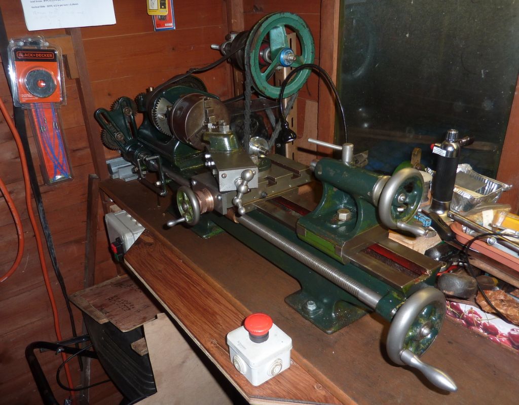
My Faircut Lathe

Advert

My Faircut Lathe

Home Forums Manual machine tools My Faircut Lathe

Viewing 15 posts - 76 through 90 (of 90 total)
  • Author
    Posts
  • #483801
    Andy Carlson
    Participant
      @andycarlson18141

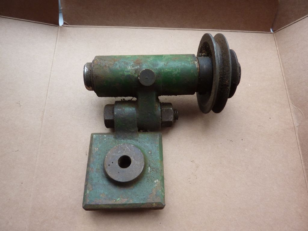
      One job that has been on my 'to do' list since I bought the Faircut was to recommission the Potts milling spindle that came with it. I suspect it may be made from a Hemingway or earlier kit.

      p1060861.jpg

      Having the ability to index in the headstock and mill slots may come in useful soon because I'm planning to make a square threaded finishing tap to help with making new feed screw nuts… as some will have seen on a separate thread.

      The spindle was fairly sound apart from being gummed up with decades of varnishy deposits but the bigger question was how to power it. My eyes alighted on the motor and drive bracket of my Unimat SL and the calipers were deployed to check the diameter of the Unimat spindle cartridge… which turned out to be 2-3mm bigger than the body of the Potts spindle.

      I spent some time keeping my eye out for a piece of plastic that was a suitable size to make a thin sleeve. I recently found a bit of UPVC (I think?) drain pipe that was about 37mm OD and just about spot on for the Potts spindle on the inside. A bit of this was sawn off and the OD turned down to suit.

      I had to make a couple of mods to the spindle. Most of my MT1 tooling would almost but not quite fit because the taper in the spindle stops dead at a step where the diameter goes down to about 5/16ths for the remainder of the spindle which is too small for the little stub on the small end of the tooling. After trying and failing to find a boring tool to get in there and also considering how the heck I was going to hold it I decided that I was either going to need to make custom collets for the spindle or else… I would stick a 3/8 drill down there. The drill plan won the day. I clamped the spindle in the 3 jaw using some lead packing to avoid marking the bearings and fed the drill about 3-4mm further into the spindle than where it had initially stopped. Problem solved

      I also noticed quite a big gap behind the thrust face at the front. The spindle has quite a big fillet radius here and the bearing only had a minimal chamfer. To sort that out I mounted the whole shooting match on an angle plate onto the faceplate and after much faffing around to centre it I part turned and part filed a bigger chamfer.

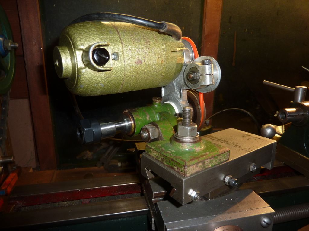
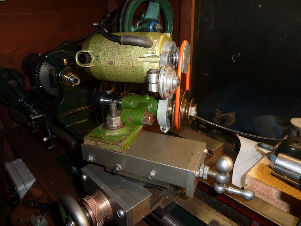
      The contraption looks rather Heath Robinson but it spins up convincingly and I'm somewhat hopeful that it will work. It certainly seems quite good at putting a protective coating of oil onto nearby surfaces.

      p1070505.jpg

      p1070504.jpg

      I may need to make some more suitably sized rubber bands and I need to arrange a suitable length of M6 studding for the drawbar.

      The ER16 holder sticks out a long way but then the Unimat motor would be in the way otherwise. I measured 1 thou of runout inside the ER16 taper which I didn't think was too bad all things considered.

      I'm sure it will be a right faff to get lined up at the correct height before use. I also need to figure out how to arrange it at 90 degrees to the main lathe axis… which I suspect will mean having the oil cap pointng downwards. I could put it on the vertical slide but then that's yet another piece of kit to juggle and find room for.

      Advert
      #484726
      Jacob Leonidou
      Participant
        @jacobleonidou84012

        Really interesting contraption you have there. I've never seen anything like it and im interested to see how it works. Looks rather scary with the motor mounted above it. Are they always mounted like that? I wonder why the engineers never used a motor with a collet holder instead of spindle and separate motor like what you have.

        #484741
        Andy Carlson
        Participant
          @andycarlson18141
          Posted by Jacob Leonidou on 09/07/2020 11:55:18:

          Really interesting contraption you have there. I've never seen anything like it and im interested to see how it works. Looks rather scary with the motor mounted above it. Are they always mounted like that? I wonder why the engineers never used a motor with a collet holder instead of spindle and separate motor like what you have.

          You need to read more old books about lathe work .

          It was probably intended to have an extra pulley and leather belt dropped down from an overhead line shaft. Exactly the kind of thing that Health and Safety was created to get rid of!

          There are some pics on lathes.co.uk of others that have had a motor fitted on a bracket like mine. I don't think it's any more scary than the Unimat SL when that is set up for milling or drilling TBH.

          If you dont already have one then I wouldnt recommend seeking one out but this one came with the lathe and it seemed rude not to use it. Nowadays one can buy cheap drilling spindles on eBay from the People's Republic that have a toothed belt pulley on the back end so the idea has not gone away. One can also buy self contained motorised spindles with an ER collet holder on the end. Not cheap though and you still need to fork out on a power supply to suit.

          #485365
          Jacob Leonidou
          Participant
            @jacobleonidou84012

            haha I need to read more books, period. Well good luck with it all, please keep all fingers clear. Wouldn't mind seeing some action pictures.

            #485513
            Andy Carlson
            Participant
              @andycarlson18141
              Posted by Jacob Leonidou on 13/07/2020 12:52:09:

              haha I need to read more books, period. Well good luck with it all, please keep all fingers clear. Wouldn't mind seeing some action pictures.

              Will do when there is something to show. The plan for upcoming jobs has more plot twists than a thriller novel (but rather less excitement) so the milling spindle has been stood down for the time being. It will come out again in due course.

              #485638
              Andy Carlson
              Participant
                @andycarlson18141

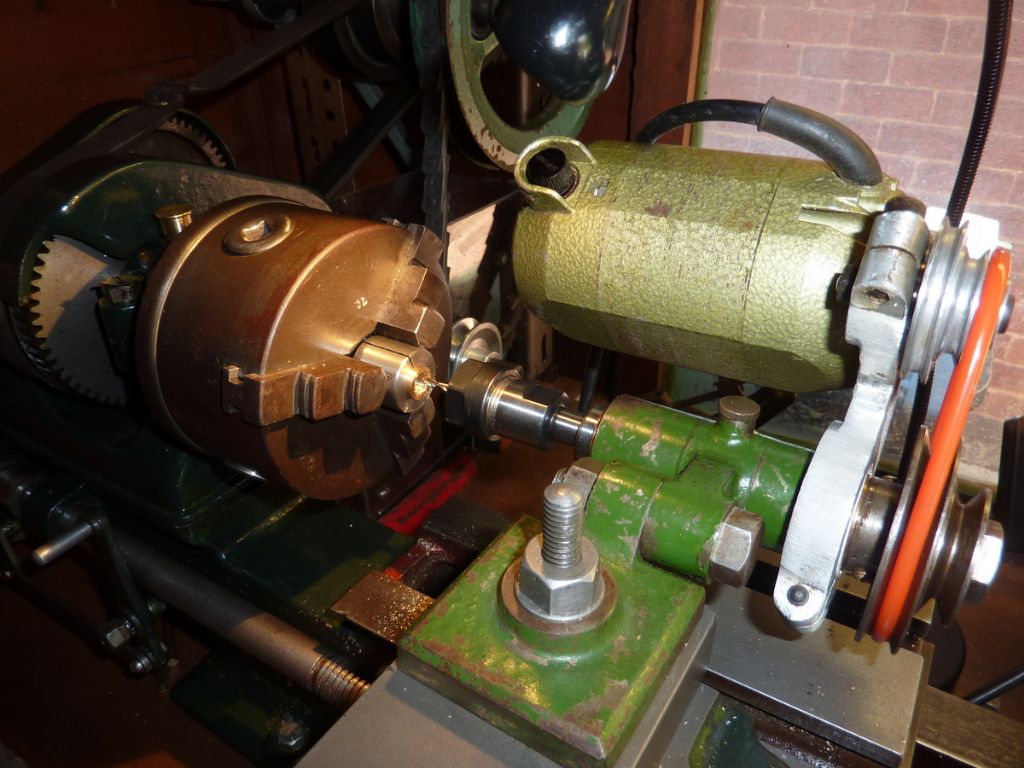
                By popular damand (well, one person)… I thought up a fairly thin pretext to deploy the milling spindle. I wanted to see if I could use it to Higbee the end threads on the practice cross slide nut. The setup was all done very much by eye, listening to the note of the (not very powerful) Unimat motor and adjusting the angle of the lathe mandrel by hand. The cutter is a 3mm Proxxon one held in an ER16 collet.

                p1070520.jpg

                Seemed to work, although I chickened out short of going quite as far around the thread as I really should and slightly marked the second thread on t'other end. Hardly a big challenge but it's a start.

                p1070522.jpg

                #486871
                Jacob Leonidou
                Participant
                  @jacobleonidou84012

                  Very impressive, what can i say. I want one now! Would you have to lock the headstock if you were to mill a vertical slot off centre on the end of something like a bar?

                  #486916
                  Andy Carlson
                  Participant
                    @andycarlson18141

                    I didn't lock the spindle for that job because I wanted to turn it by hand as part of the operation. I do disconnect the power because at some point I WILL hit the lathe start button by mistake when intending to switch on the milling spindle.

                    I did lock the headstock spindle when using the milling spindle when cutting the flutes on the tap. Unfortunately there is no straightforward way provided by the lathe. The drive belt/pulleys dont help because the play in the bull gear peg or backgear means that the spindle can still rock a little. My answer is to use the change gears. I add an extra (bigger diameter) washer outside the gear on the first banjo stud and then put the usual washer and nut back on. This prevents the gear from rotating. The collar on the tail end of the spindle also needs to be tight to prevent any movement there otherwise the gear can rock a little bit on the locating pin. Select the right tooth count, add some chalk marks on the relevant teeth and you have a headstock dividing setup.

                    When done I disengage all of the locked drive train before plugging the power back in.

                    #487033
                    Jacob Leonidou
                    Participant
                      @jacobleonidou84012

                      Sounds like a pain to go through all that for the simple purpose of locking the spindle. I do like the dividing idea! That was going to be my next question. Good work!

                      #487038
                      Jacob Leonidou
                      Participant
                        @jacobleonidou84012

                        Im assuming by the right change gear you mean one with an even number of teeth?

                        #487040
                        Andy Carlson
                        Participant
                          @andycarlson18141
                          Posted by Jacob Leonidou on 22/07/2020 07:59:55:

                          Im assuming by the right change gear you mean one with an even number of teeth?

                          Depends what you need for the job really – a gear with a number of teeth that is a multiple of the number of divisions that you need for the job.

                          Using the gears to lock the spindle is pretty quick if everything is to hand – just taking one nut off the banjo, adding a washer and then putting it back on. Cleaning the oil off the mandrel gear and chalking it in the right places takes a bit longer.

                          I wouldnt use this method (or the backgears) to lock the spindle for anything involving shock loads though.

                          #495351
                          Andy Carlson
                          Participant
                            @andycarlson18141

                            A little project that has been rumbling along since June. So far it's been living on another thread (LINK) while I have been practicing on some spare lathe parts but I think it's time to move it back onto my lathe thread.

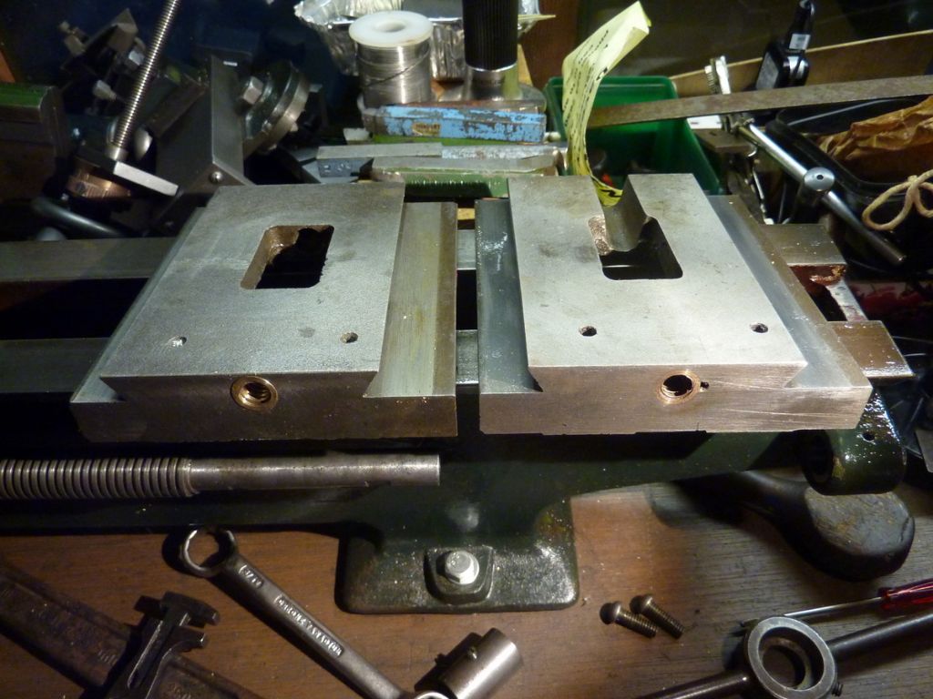
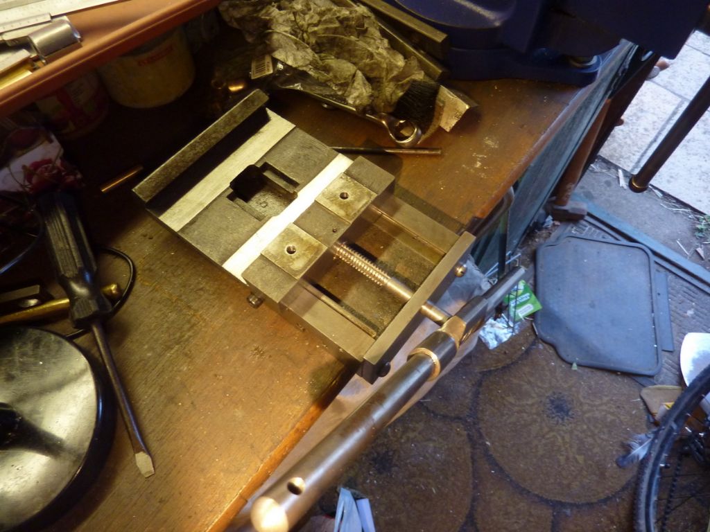
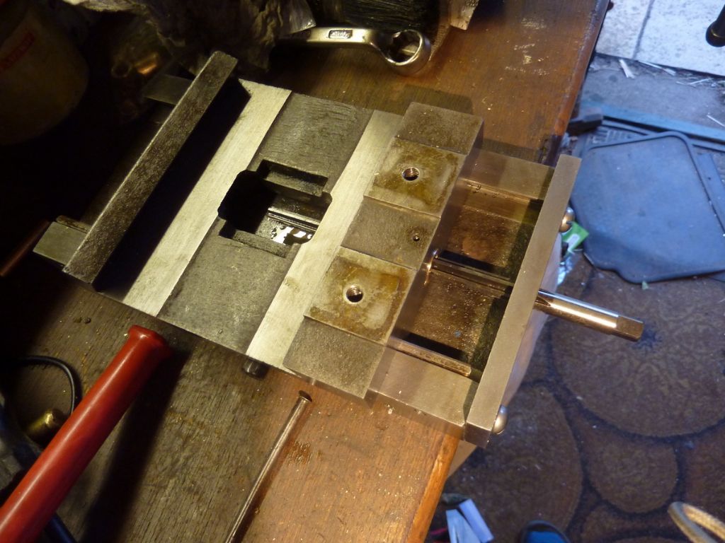
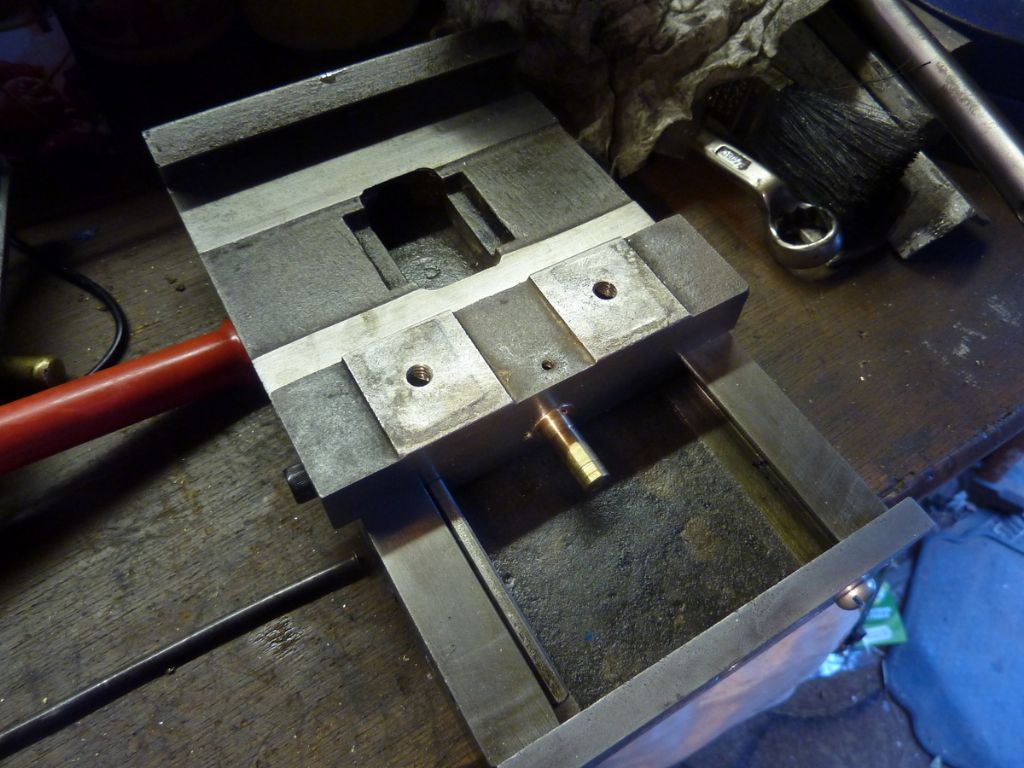
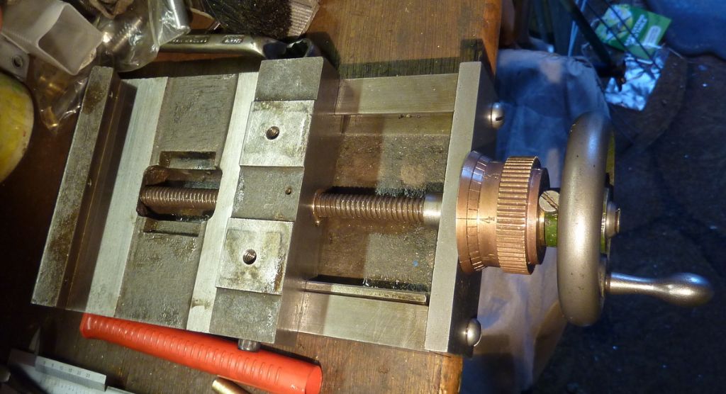
                            The basic problem is backlash in the cross slide – partly from wear in the feed screw and partly the nut. I've measured it at 45 thou at the worst. Today was the first time I'd looked really closely at the cross slide nut. The wear looks pretty scary so it's a good thing that I've been working on a fix.

                            p1070614.jpg

                            As a quick recap… the nut is a non ferrous part pressed into the saddle casting. This means it is replaceable but it's not easy… what with it having a 12 TPI square thread and a none too generous bore. My first attempt was to make the nut as a fully finished article. When I pressed it into the saddle it did not align well enough with the lengthy clearance bore in the casting – to the extent that the feed screw fouled the hole towards the rear of the saddle. I think the original thread was cut in situ so I've decided that I need to at least finish the thread using a tap in situ.

                            Here is dry run number 3 with tap number 1 in July and fitted to in the 'spare' saddle and cross slide that I bought last November.

                            p1070540.jpg

                            As readers of the other thread may recall the tap had issues because the thread cutting tool (a recycled cheapo chinese HSS milling cutter) chipped during use and the thread grooves ended up too wide for a reason I did not figure out at the time. The good news was that the result was a working cross slide, even though the nut will only accept a very worn feed screw.

                            After leaving the job alone for a while I came back to it and decided to replace both the cutting tool and the raw material for the tap. A new tool was made from 6mm round HSS bought from RDG Tools. This took a couple of attempts to get right and grinding a 1mm wide threading tool from 6mm stock was pretty time consuming. The silver steel for tap 1 was from a well regarded UK supplier but I found it intermittently 'gritty' both on this and another job so I bought a new piece from a different supplier – Coventry Grinders.

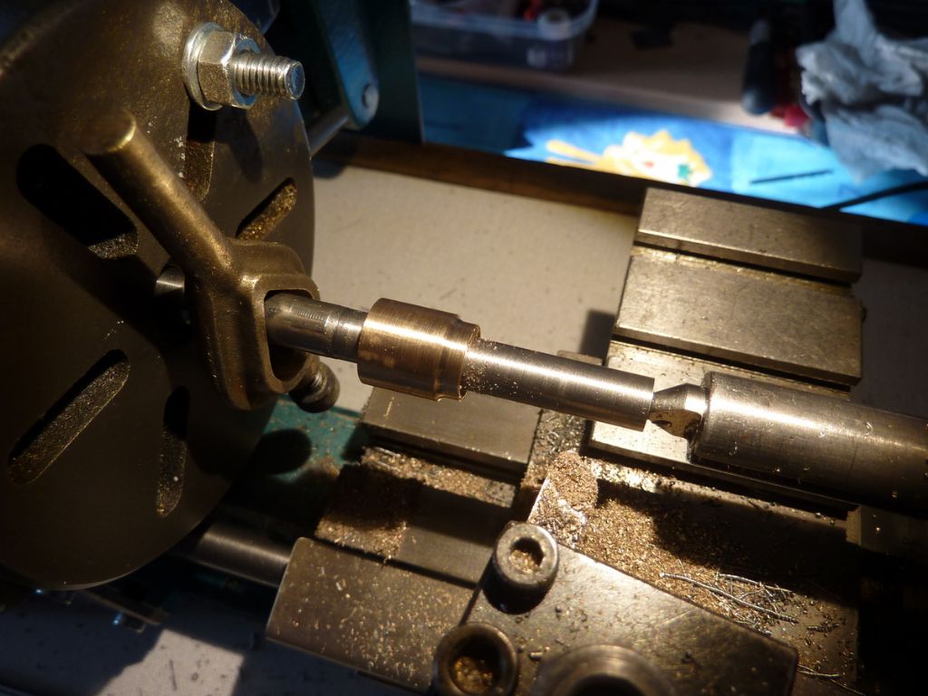
                            Tap number 2 (again) wound up with the grooves too wide, much more severely than tap 1. This time I spotted what was going wrong. The job produces a lot of vibration and I was paranoid that the tailstock centre was becoming less firmly engaged with the job so I kept tweaking the handwheel. What was actually happening was that the tailstock tweaking was pushing the job a thou or so further into the chuck and messing up the registration of the threading tool, causing the wider groove. Armed with this experience I made tap number 3 keeping my hands off the tailstock wheel and that one worked out OK (finally!). Using tap 3 to recut nut number 3 I was finally able to get a test piece of unworn male thread to fit properly… natually the worn feed screw then had backlash.

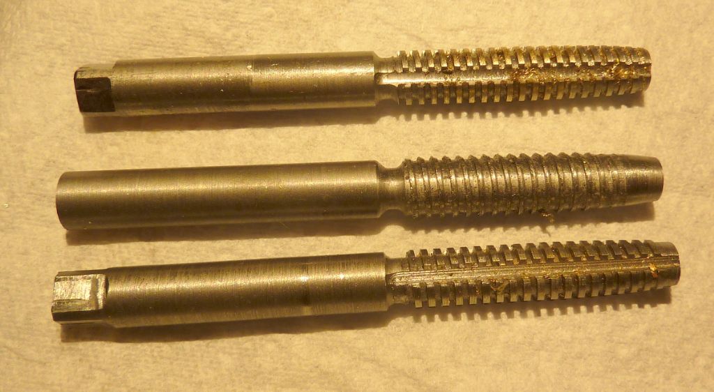
                            The three taps – tap 1 at the top.

                            p1070617.jpg

                            Today I've finished dry run number 4. This time I ground the thread cutting tool a few thou undersize to leave more metal for the tap to remove so that any alignment errors will be dealt with by the tap.

                            My next step was to get some 'insurance' in case the job on the 'proper' cross slide goes wrong. After a lot of fiddling about and swapping bits around, I managed to get the spare saddle and cross slde to work on my lathe. The fit is usable rather than perfect – it seems that repeatability wasn't a strong point in the Faircut factory.

                            p1070609.jpg

                            While I had everything apart I noticed that the two saddles were more different than I thought. Both have aspects that are not ideal so I wonder which was earlier and which was the 'improved' design.

                            p1070610.jpg

                            p1070611.jpg

                            The lathe is now reunited with its proper saddle and cross slide ready to make what I hope will be the proper cross slide nut. This will be made from leaded gunmetal rather than the brass used for the dry runs… but that's a job for another day.

                            #495602
                            Andy Carlson
                            Participant
                              @andycarlson18141

                              I've put my extra brave head on today – decided that I'd done enough practice and it's time to fit the replacement cross slide nut for real.

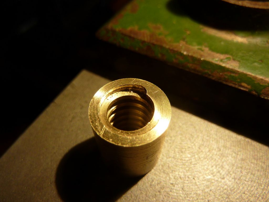
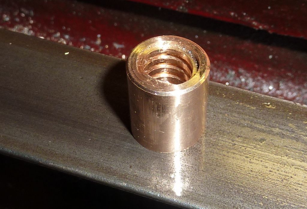
                              New nut made as per practice nut 4 but using leaded gunmetal…

                              p1070646-001.jpg

                              Stripped the lathe to take the old nut out… and found that the hole in the casting was a few thou smaller than the spare so too small for my 9/16 brass bar press tool.

                              Reassembled enough of the lathe to shave a few thou off the diameter…

                              Stripped the lathe again…

                              Took a deep breath and pressed the old nut out…

                              Good grief!!!

                              p1070647-001.jpg

                              It's over to the Cowells now… I'm still hoping to get the new nut fitted today in spite of a few curve balls.

                              #495658
                              Andy Carlson
                              Participant
                                @andycarlson18141

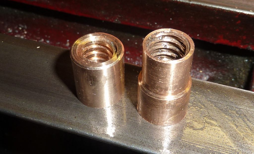
                                Cowells to the rescue. Being based on what turns out to be the wrong design the modified nut is 7mm shorter than the one that I took off but 14mm of new thread seems like a better bet than 21mm of paper thin thread.

                                p1070650.jpg

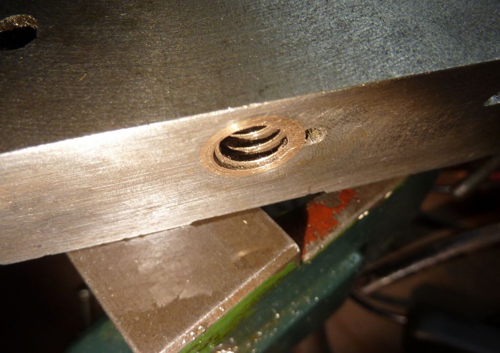
                                Pressed into the saddle and tap deployed to open out the thread…

                                p1070651.jpg

                                Feed screw would not go in… checked with the plug gauge and found that the tapping had raised burrs and closed up the minor diameter… tapered reamer deployed…

                                p1070652.jpg

                                plug gauge goes in now…

                                p1070653.jpg

                                Feed screw still wondn't go in. tap, plug gauge, ream, plug gauge, repeat (about three or four times IIRC).

                                Yay!!

                                p1070655.jpg

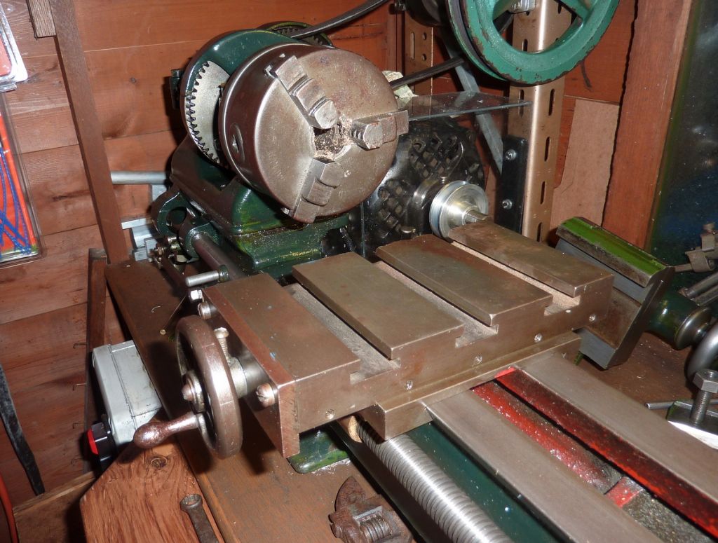
                                Lathe all back together
                                p1070657.jpg

                                Backlash seems a lot better but I haven't measured it yet – spent the rest of the evening cleaning up the carnage around the Faircut and the Cowells.

                                #495732
                                Brian Morehen
                                Participant
                                  @brianmorehen85290

                                  Hi Andy.

                                  Looks good worth all of the time and patience and problems on the way , guess you are pleased with the end result

                                  enjoy your bottle of champers Have forgot how many screw threads i made for my cross slide be for i was happy

                                  Regards Brian

                                Viewing 15 posts - 76 through 90 (of 90 total)
                                • Please log in to reply to this topic. Registering is free and easy using the links on the menu at the top of this page.

                                Advert

                                Latest Replies

                                Home Forums Manual machine tools Topics

                                Viewing 25 topics - 1 through 25 (of 25 total)
                                Viewing 25 topics - 1 through 25 (of 25 total)

                                View full reply list.

                                Advert

                                Newsletter Sign-up