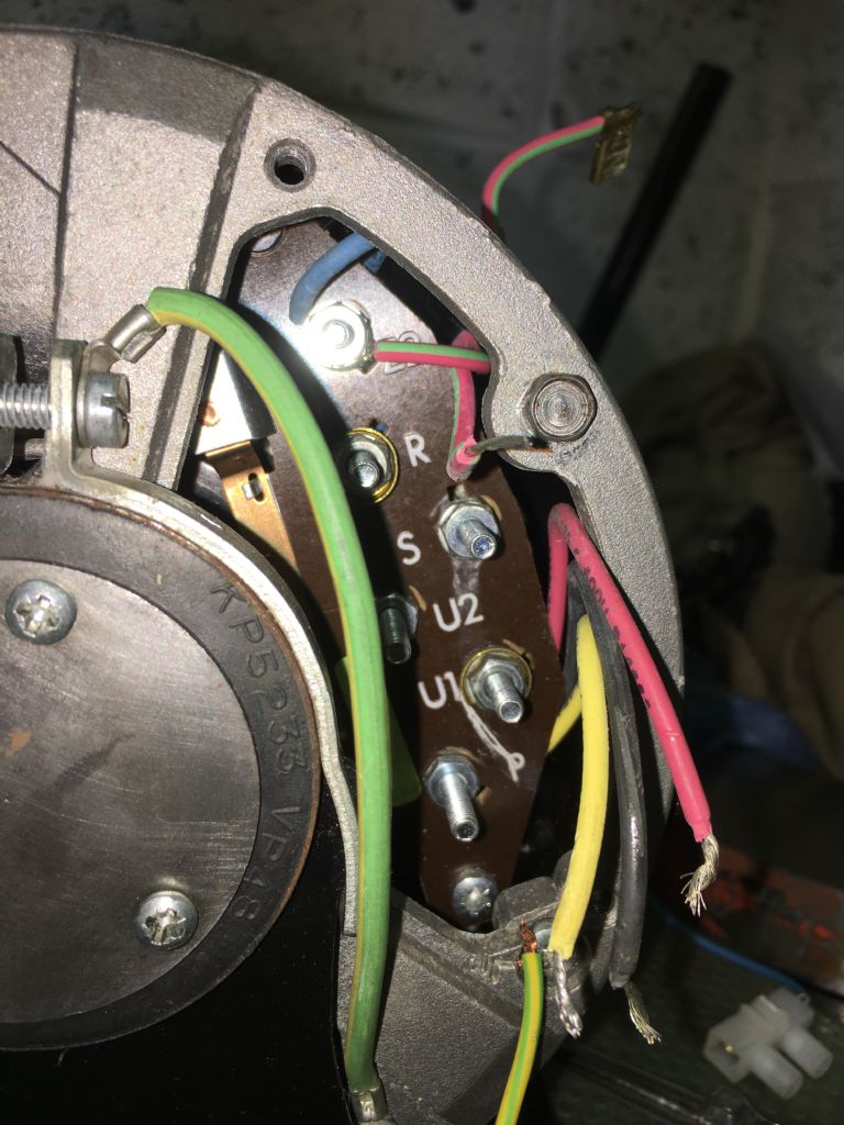
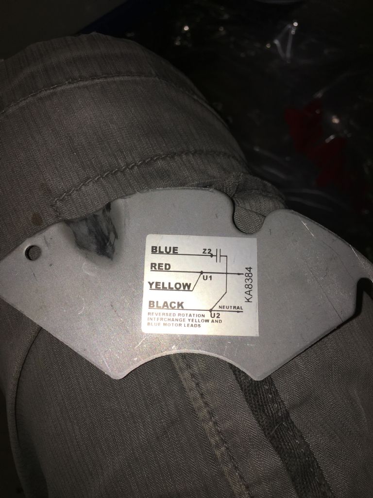
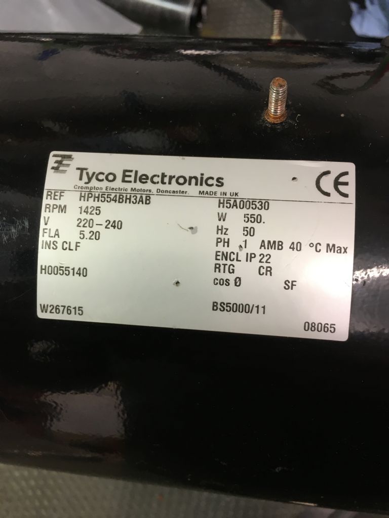
Motor wiring
Motor wiring
- This topic has 11 replies, 5 voices, and was last updated 5 June 2018 at 22:46 by
Phil Boyland.
Viewing 12 posts - 1 through 12 (of 12 total)
Viewing 12 posts - 1 through 12 (of 12 total)
- Please log in to reply to this topic. Registering is free and easy using the links on the menu at the top of this page.
Latest Replies
Viewing 25 topics - 1 through 25 (of 25 total)
-
- Topic
- Voices
- Last Post
Viewing 25 topics - 1 through 25 (of 25 total)
Latest Issue
Newsletter Sign-up
Latest Replies
- Amadeal AMABL210E Review – Any Requests?
- New member looking for help
- My experiences with an ELS lathe
- Martin Evans ‘SIMPLEX’ boiler bush thread form?
- Readability / clarity in new combined magazine
- TurboCAD Snaps and Dimensioning?
- Meddings MF4 Manual
- Boolean bewilderment
- Dial test indicator vs Dial indicator
- road registration and traction trailer.


