ML10 – ready for the boneyard?

Advert

ML10 – ready for the boneyard?

Home Forums Workshop Tools and Tooling ML10 – ready for the boneyard?

Viewing 25 posts - 51 through 75 (of 105 total)
  • Author
    Posts
  • #365010
    Ignatz
    Participant
      @ignatz

      Martin, might be a bit wrong with this, but bear with me.

      Currently, I can force some movement of the main spindle at the chuck end by virtue of inserting my fist underneath and exerting pressure. I am reading a total deviation of about 0.035mm ( = 0.00138 inch ). I am thinking that a cutter working against a rotating steel workpiece will generate even more force, so my readings may be 'conservative'.

      Quoting Hopper from another post:

      "Myford's factory inspection sheet specifies 0 to .0003" runout on the spindle, for a brand new lathe leaving the factory. "

      … so it looks like my machine is showing wear of something between four and five times the amount of normal runout as compared to the lathe when new.

      The best way to correct that would be with a brand new replacement spindle. We all know that Myford stopped supplying spares for this old girl a long time ago, so that leaves the alternate approach of tightening the casting journal.

      But is it not so that if I (delicately) lap the headstock shim to allow the iron casting to close a bit more snugly around the main spindle to take up some of that wear that I am, in essence, forcing the spindle slightly downwards… thus changing its angle with respect to the bed way?

      Would it then not make more sense to first take out the play in the main spindle and only after that check the spindle headstock alignment?

      Advert
      #365026
      Martin of Wick
      Participant
        @martinofwick

        Currently, I can force some movement of the main spindle at the chuck end by virtue of inserting my fist underneath and exerting pressure. I am reading a total deviation of about 0.035mm ( = 0.00138 inch ).

        Ignatz,

        The play in the bearing is unfortunate, but recoverable. Is there significant side to side play, which is more of an issue?

        Difficult to predict what will be worn and where, so I don't think you will 'push' the spindle down at the nose as you imply, even if you do, that will be less significant than any side to side play

        The effect of squeezing the bush down will be to close that area of wear slightly, hopefully reducing play. In any case up and down play in the spindle of +- half a thou would probably not account for the amount of taper you have measured (side to side play might).

        Spindle play generally manifests as poor finish rather than a tapered cut, but the forces at the tailstock end of the piece when cutting, could in theory deflect the spindle in the bearing sufficient to result in a shallower cut at the tailstock end ( and so can deflection of the work piece)

        Proceed as you wish, but if it were my machine, I would do the simple checks first, headstock alignment and twist. It is easier and safer to deal with these before hacking the bearing!

        If you still have a significant taper on a test piece after confirming the alignment is OK and there is no twist (and you have mounted the work deep in the chuck to avoid the effects of the jaw belling) then it is time to look at the bearing.

        Check front and back bearings/spindle contact for play both lateral and vertical, The front one will have suffered the most impact, but they need to be considered together. The amount of wear is not that great an you have the right approach – proceed delicately! Lap off half a thou at a time from the shim and recheck the spindle movement. Personally, anything less than 1/2 a thou play static would do me. If you go tighter, make sure to run the lathe up at high speed for half an hour (with oil) and check to see the bearings are not warming up unduly.

        If you are going to the trouble of adjusting the bearing shims, you may want to consider taking the spindle out to remove any gunk/swarf etc from the bearings giving the lot a good clean. It is unlikely you will damage the headstock with the level of adjustment proposed, just make sure you remember to reinsert the shim before cranking down on the bearing bolt and check spindle rotation by hand as you tighten up STOP as soon as the spindle starts to feel the least bit tighter

        You will never reduce the errors to zero so don't sweat the small stuff!

        #365042
        Neil Wyatt
        Moderator
          @neilwyatt
          Posted by Ignatz on 01/08/2018 16:31:39:

          Martin, might be a bit wrong with this, but bear with me.

          Currently, I can force some movement of the main spindle at the chuck end by virtue of inserting my fist underneath and exerting pressure. I am reading a total deviation of about 0.035mm ( = 0.00138 inch ). I am thinking that a cutter working against a rotating steel workpiece will generate even more force, so my readings may be 'conservative'.

          Quoting Hopper from another post:

          "Myford's factory inspection sheet specifies 0 to .0003" runout on the spindle, for a brand new lathe leaving the factory. "

          … so it looks like my machine is showing wear of something between four and five times the amount of normal runout as compared to the lathe when new.

          Don't confuse play in the spindle with runout, they aren't the same thing. A spindle in plain bearings needs clearance and for a 1 1/2" spindle a thou and a half would be about right for a close running fit.

          This won't necessarily translate to excessive play when the spindle is running with adequate lubrication and under load.

          For comparison I googled to see what sort of play other people have:

          "I can measure 0.010-0.015" of vertical movement when I pick up on the chuck. Seems like a lot to me."

          Edited By Neil Wyatt on 01/08/2018 19:35:44

          #365044
          Ignatz
          Participant
            @ignatz

            Neil, that is comforting to know. However…

            I've just tested the front-to-back play on the main spindle bearing. In that direction when I attempt to force the chuck to move I measure about 0.02mm ( = 0.00079 inch ) which is only about half of what I measured vertically.

            I am also assuming that after forty to fifty years of occasional on-and-off use the 0.02mm I measure is already more generous than when brand new.

            But this does suggest that snugging down the casting to make the vertical play equal that of the horizontal would not be amiss. Am I wrong in this?

            #365047
            Martin of Wick
            Participant
              @martinofwick

              Spotted Neil,

              I thought it looked a bit tight, obviously at eyes glazed over at runout and just assumed play was what was meant.

              Having said that, I can hardly detect any play in in the spindle on my 10, sub 1 thou, but it doesn't seem to get warm when run, so that was my justification for 1/2 a thou on play.

              I guess if you were really working the lathe in an industrial environment you might want a bigger clearance.

              BTW, what in your view would wear more in steel to iron bearings, the spindle or the iron bearing itself? someone told me once that you get a sort of carbidey type glaze on the surface of the iron, and counter-intuitively it is the hardened steel spindle that wears more… is that possible?

              #365094
              Hopper
              Participant
                @hopper
                Posted by Martin of Wick on 01/08/2018 14:56:58:

                Posted by Hopper on 01/08/2018 11:19:40:

                Agreed, if you only consider radial runout of the chuck. Radial runout doesn't matter that much. However, you also need to consider the axial runout, and 1+ thou runout behind the chuck is small and probably not the main cause of error in this case, but if it was 2 or 3 thou, you might expect 4 to 6 thou angular deviation 100mm out from the point of measurement if that error was consistent through the chuck body (because it might only be the back face of the chuck/backplate that is out).

                Try this experiment, take a small piece of straight thick wire, put a slight bend in it, imagine one side is the work piece in the 'bent chuck' and the other side the spindle, twirl the 'spindle' side between thumb and forefinger as if in the headstock, observe the circle described by the workpiece end and then imagine a tool cutting on an axis parallel to the spindle – result is a taper cut (as you may get with workpiece set poorly in a bellmouthed chuck).

                No way can a tool cutting parallel to the lathe axis cut a taper as you describe. Does not happen. Go out in your shed and try it if you doubt it. Bend a bit of bar in the vice and then hold it in the chuck and take a cut over it.

                #365095
                Hopper
                Participant
                  @hopper
                  Posted by Martin of Wick on 01/08/2018 19:53:18:

                  BTW, what in your view would wear more in steel to iron bearings, the spindle or the iron bearing itself? someone told me once that you get a sort of carbidey type glaze on the surface of the iron, and counter-intuitively it is the hardened steel spindle that wears more… is that possible?

                  Is the spindle even hardened? The original ML7 spindles were not and as the ML10 was the budget model it would be surprising if they were.

                  #365097
                  Hopper
                  Participant
                    @hopper
                    Posted by Ignatz on 01/08/2018 19:46:42:

                    Neil, that is comforting to know. However…

                    I've just tested the front-to-back play on the main spindle bearing. In that direction when I attempt to force the chuck to move I measure about 0.02mm ( = 0.00079 inch ) which is only about half of what I measured vertically.

                    I am also assuming that after forty to fifty years of occasional on-and-off use the 0.02mm I measure is already more generous than when brand new.

                    But this does suggest that snugging down the casting to make the vertical play equal that of the horizontal would not be amiss. Am I wrong in this?

                    The .0007" is maybe a tiny bit more than you might like, but it's not too bad. About .0005 – .001" is pretty good on these old lathes. You might reduce the vertical movement by carefully tightening the clamping bolt on the split bearing as described in the post above. To tighten it up half a thousandth or so may not even require the shim to be removed. Just tightening the bolt could do the job.

                    Certainly, the amount of play you have now is not enough to cause the kind of taper you are turning.

                    And you can compensate to a degree for bearing wear by putting thicker oil in the bearings. I use 20/50 engine oil in mine (which will have the purists baying for blood) quite successfully.


                    Edited By Hopper on 01/08/2018 23:41:14

                    #365117
                    Ignatz
                    Participant
                      @ignatz

                      Placed an order for the ground silver steel stock and so forth. Should be arriving early next week. Then I can go further with testing spindle alignment.

                      Thanks to everyone up to this point for the really solid and helpful advice! yes

                      #365120
                      pgk pgk
                      Participant
                        @pgkpgk17461

                        Just as a theoretical thought..

                        Bed wear on a hobby machine will usually be by the headstock end. So a large diameter tube unsupported by tailstock and a length skimmed well away from the headstock might be another worthy test? Unless one gets into a goldilocks zone on the area of bed twist?

                        pgk

                        #365819
                        Ignatz
                        Participant
                          @ignatz

                          Received my steel stocks from the supplier the other day. So, on with the testing…

                          Rollie's Dad's Method of Lathe Alignment

                          Almost immediately I realized that the method has its limitations. This deviation test would work very well if we assume that the bed of the lathe is flat and true. That is not the case with my old ML10 where there is definitely wear on the saddle. This means a hollowing at the chuck end, vertically… and also horizontally bacause of the wear on the dovetail and gib… I am assuming there is also some wear to the carriage slide (bellmouthing?) where it contacts the rear dovetail of the bed.

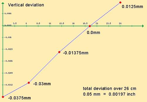
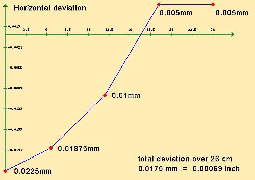
                          So rather than simply take a deviation reading from the chuck end as well as at one spot further out, I elected to take a series of stepped readings along the length of my test bar. I chucked up a length of 14mm silver steel and proceeded to test horizontal and vertical deviations in the manner suggested. I did this at five locations along the test bar, starting 1cm away from the jaws of the chuck and then at four other locations, each time 6.5cm further on down the length of the test bar towards the tailstock end of the lathe. At each test location I tightened up the carriage locking screw.

                          The five locations are thus: 0cm, 6.5cm, 13cm, 19.5cm and 26cm

                          vertical deviation readings.jpg

                          The vertical readings suggest a condition of 'spindle high' towards the tailstock. But is this just a trick of the low readings due to saddle wear near the chuck end of the lathe?

                          horizontal deviation readings.jpg

                          The horizontal readings are also much more out at the chuck end… resolving to what would indicate correct alignment at the tailstock end (where there would be far less dovetail wear).

                          And, oh yes…

                          One other problem I found is a certain amount of what I will term 'Vertical Oil Film Droop'. This must be attributed to wear in the main spindle and journal. When turning the test bar the measurement would start at one reading, but rapidly change as the end of the bar sagged… doubtless due to the weight of the chuck and workpiece forcing the spindle down through the layer of oil between it and the cast iron journal.

                          I measured this 'droop' at 0.02mm ( = 0.0008 inch ) out 26cm away from the chuck.

                          I don't know if the deviations I've measured are necessarily so bad for this old machine. In any case, I wanted some feedback on the results before I start tinkering with the headstock mount and playing around with shimming.

                          After that I can try some test cuts for parallel on some free maching steel I've secured.

                          #365837
                          Hopper
                          Participant
                            @hopper

                            If I had an old lathe that was within .00069" of alignment horizontally over 26cm (10 inches) I'd consider myself blessed. Hell, if I could even accurately measure anything to within .00001" in my home workshop I'd consider myself blessed.

                            Vertical alignment is nowhere near so critical. Until you get down to very very small diameters, the surface of the job where it meets the tool is virtually vertical so the tool being a tad higher or lower makes very very little difference to the turned diameter of the job. GH Thomas discussed this at length in one of his books, I forget which one.

                            I'd leave things well alone until I took a fine test cut over a four to six inch length of 1" bar and see how it measures up.

                            Yes, you will get some droop over 26cm of 14mm bar. Quite a bit in fact. ISTR in Connelly's MC Tool Reconditioning book he says a piece of 1" bar 6" long will droop by .0004". I would imagine almost double the length at almost half the diameter would have considerably more.

                            Re oil film "sag", when making these types of precision measurements, it is customary to run the lathe for 20 minutes at medium to high speed first, to get things up to operating temperature and conditions.

                            Let us know how your turning test on a piece of 1" bar measures up. Will be real interesting to see how it compares with the static test already done. Theoretically, based on the deviation of .00069" already measured, it should be pretty good.

                            #365839
                            Martin of Wick
                            Participant
                              @martinofwick

                              Ignatz

                              I don't know if the deviations I've measured are necessarily so bad for this old machine. In any case, I wanted some feedback on the results before I start tinkering with the headstock mount and playing around with shimming.

                              After that I can try some test cuts for parallel on some free maching steel I've secured.

                              from your figures I think you have conclusively proved there is nothing much wrong with your lathe! You would be hard put to find anything affordable in the hobby market giving much better results than < half a thou out at 6 inches, whether you think it is wear or alignment causing the issues.

                              Try to bear in mind also that the spindle also needs some freedom to move, so I don't think there is excessive bearing play either- less than a thou 10 inches out? come on!!! how much better do you expect it to be?

                              Time to stop chasing your tail and start having fun making something useful.

                              #365864
                              Ignatz
                              Participant
                                @ignatz

                                OK… I'll find some time later on this evening or early tomorrow to run a test piece for parallel.

                                #366142
                                Ignatz
                                Participant
                                  @ignatz

                                  Just ran my first cylinder turning test using 25mm free machining stock.

                                  I chucked it up nice and tight in the 3-jaw, skimmed off until I was turning clean everywhere and finished up with a final pass, one thousand deep using some cutting oil.

                                  The measurements with my micrometer were taken along a 9cm length, starting 1.5 cm away from the end of the chuck jaws. Each measurement was taken 1.5 cm further on towards the tail end of the lathe.

                                  The readings were:

                                  24.3125mm — 24.335mm — 24.353mm — 24.36mm — 24.363mm — 24.355mm — 24.351mm

                                  This gives me a cylinder whose diameter varies by 0.0505 mm ( = 0.00199 inch ) over a length of four inches. But, in truth, the major portion of that variation is occuring over only half that length.

                                  Hopper suggests that 0.001 inch of difference over a length of six inches would be good for an old machine, so these results don't seem so very good to me.

                                  Not only is there more variation than desired, but of course, most of it is within 4 cm from the end of the chuck… right where one would most expect it on an older machine… and right where one does the majority of one's work.

                                  Edited By Ignatz on 07/08/2018 16:14:35

                                  #366145
                                  Ignatz
                                  Participant
                                    @ignatz

                                    … Oh yes, I forgot to mention that even though the turned tolerances of my test piece is disappointing, the surface finish of that piece of free machining stock didn't look so bad. wink

                                    #366221
                                    Hopper
                                    Participant
                                      @hopper

                                      Posted by Ignatz on 07/08/2018 16:13:34:….

                                      ….

                                      24.3125mm — 24.335mm — 24.353mm — 24.36mm — 24.363mm — 24.355mm — 24.351mm

                                      What are you using to measure down to .0001mm with? You really can't measure that accurately in most home shop environments without temperature control and long experience at using such sensitive instrumentation. Normally, micrometers and dial indicators with a resolution of .01mm is used for this type of work. More sensitive instruments cause problems due to user error, mounting flex etc.

                                      Working to the usual hundreths of a mm, your readings would be something like

                                      24.31 — 24.33 — 24.35 — 24.36 — 24.36 — 24.36 — 24.35

                                      So for us fossils who still work in imperial, that works out to a variation of .04mm or .0016", which is pretty good for a lathe that has not yet had the bed mountings shimmed.

                                      What you need to do next is put a thin shim under one of the lathe's mounting feet at the tailstock end. To correct for a test piece that is larger at the tailstock end like yours is, you will need to put a shim under the FRONT of the lathe mounting at the tailstock end. (The lathe mounting where it is bolted to the bench top, not where the lathe stand is bolted to the floor.). Thickness of the shim is by trial and error. You might start with .005" thickness. Beer can material is traditional! Cut a square about 40mm square and then cut a slot into one side of it about 12mm wide, so the piece ends up a U shape that you can slide under the mounting foot with teh U surrounding the mounting bolt. Then tighten down the bolts and take another test cut.

                                      Another point is that it's best to use a very sharp high-speed-steel toolbit for these tests. Using carbide insert tooling on such fine cuts can provide false reading as the insert can tend to rub rather than cut cleanly.

                                      Also, you might try holding the test piece in the four jaw chuck if you have one. It holds more firmly than a three jaw and is usually less likely to be bell-mouthed slightly, which can skew readings toward larger at the tailstock end.

                                      For a full description of the bed-mounting shimming process, see page 13 of the Myford ML7 User's Manual. It is freely available for download on the internet as it is long out of print and copyright is no longer enforced by the holders. More information here **LINK**

                                      Edited By Hopper on 08/08/2018 05:25:00

                                      #366222
                                      Ignatz
                                      Participant
                                        @ignatz

                                        Hopper,

                                        I'm using a regular metric micrometer, divided into the usual hundred gradations per millimeter. The extra digits are my estimates of the 'between' position of the scale around the reading mark. I agree with your rounded off figures.

                                        The cuts were indeed taken using a very sharp HSS cutter. As I mentioned, the actual surface finish on the steel was rather nicer than on 'scrap bin' stock.

                                        After running this test I got my eyes down low and up close and personal with the underside of the front dovetail on the bed way. It didn't look so good. Evidence of long, deep scratches there, doubtless the work of cutting swarf between gib and dovetail. Under the finger it feels rather rough, certainly in comparison to how baby smooth the dovetail feels at the (unused) tail end of the lathe.

                                        Yes, I could try some shimming under the bed, and although it might help that portion of the cut out away from the headstock, I have my doubts about the area closest to the chuck. One would be asking for rather a fair amount of twist – and just along that short section of bed – to correct for the difference. I'm really thinking that this is a case of accumulated wear over time.

                                        #366225
                                        Hopper
                                        Participant
                                          @hopper

                                          Yes, there will be wear over time. No doubt about it.

                                          But still worth reading the User's Manual on the shimming procedure recommended by Myford, and tested with a four to six-inch test piece so it must influence performance up close to the chuck, which I agree seems surprising but is the way it works.

                                          Plus tightening up the headstock bearing may take up some of the taper turning tendency.

                                          It's worth a try.

                                          Otherwise, just start using the lathe and see how it works in practice. A few seconds with some emery tape on the job at full rpm will remove one or two thou of taper on critical jobs.

                                          #366226
                                          Michael Gilligan
                                          Participant
                                            @michaelgilligan61133
                                            Posted by Michael Gilligan on 01/08/2018 09:11:16:

                                            Posted by Neil Wyatt on 01/08/2018 08:56:17:

                                            Posted by Michael Gilligan on 31/07/2018 16:51:31:

                                            It's a pity they didn't build it with a replaceable bed-plate,

                                            like the Hardinge DV/ DSM-59

                                            As the ML10 was Myford's 'budget' machine I suspect they weren't planning to compete with Hardinge

                                            .

                                            Clearly, Neil

                                            Subtlety of wording : I did NOT mention anything about competing with Hardinge, I simply highlighted one feature of the DV/DSM lathes which would have been of great advantage to Myford ML10 customers, and might have added only a modest incremental cost if it had been engineered into the design.

                                            angel MichaelG.

                                            .

                                            Ignatz,

                                            Despite Neil's reply, I was quite serious about the advantage of a replaceable bed-plate … and I think your current experiences demonstrate the point nicely.

                                            I don't know the detailed dimensions of each profile, but I think you will find that they are sufficiently similar to demonstrate that the arrangement would have been practical; and may even be feasible as a not-inexpensive retrofit.

                                            If the existing dovetail edges were machined off the ML10 bed; a top plate, in the Hardinge style, could be fitted: This would increase the centre height of the Myford, but retain its working profile. This might be worth doing on your Myford, but it obviously depends on how good the rest of the components are, and whether you are on good terms with a grinder !!

                                            MichaelG.

                                            .

                                            For inspiration: http://www.babinmachine.com/index.php?HARDINGEDV59

                                            Edited By Michael Gilligan on 08/08/2018 08:25:49

                                            #366227
                                            Hopper
                                            Participant
                                              @hopper

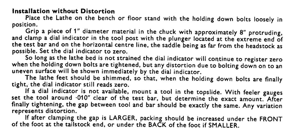
                                              Following Myford's standard procedure for shimming the bed feet to get the lathe cutting straight would be a lot easier.

                                              #366229
                                              Michael Gilligan
                                              Participant
                                                @michaelgilligan61133

                                                Myford's ML10 instructions:

                                                img_2111.jpg

                                                #366230
                                                Ignatz
                                                Participant
                                                  @ignatz

                                                  So I'm left with a few choices.

                                                  Tighten up the main journal a wee bit and try to shim the bed a bit. Couldn't hurt and might help. At that point I would just continue to use the lathe as it is until a better option (new or used) presents itself.

                                                  Totally agree that a replaceable bedplate would have been just the ticket for the ML10, most especially given the fairly straightforward profile. But that is all in hindsight as Myford chose not to take that route. And, yes, one could elect to have that sort of thing done, but this demands access to larger machine tools which I do not have. Paying for same – let alone finding someone with the necessay expertise for such an adventure – would seem to be prohibitive.

                                                  Regrinding the bed is always possible. Pursuant to that I got in touch with Myford Solutions in Holland. The bare minimum would be to true up the bed way with a surface grinder, clean up the dovetails on a Bridgeport and similarly treat the carriage and the gib. The price for this is at least €500 and that is not even allowing for the cost of shipping the bed and carriage up and back (since I don't have a car) . If I went further and had the man do both the cross slide and tool post slide it would bring the cost up above €750. Pretty high considering that the feed screws and nuts would still be doubtful… and again, that is a hefty chunk of the cost of a new lathe.

                                                  I'm hoping to perhaps find someone in my own area (Gent, Belgium) to do the work, but we don't enjoy the same healthy engineering hobbyist community as up in the UK so my search may be both long and in vain.

                                                  #366232
                                                  Mick B1
                                                  Participant
                                                    @mickb1
                                                    Posted by Michael Gilligan on 08/08/2018 08:22:08:

                                                    If the existing dovetail edges were machined off the ML10 bed; a top plate, in the Hardinge style, could be fitted: This would increase the centre height of the Myford, but retain its working profile. This might be worth doing on your Myford, but it obviously depends on how good the rest of the components are, and whether you are on good terms with a grinder !!

                                                    MichaelG.

                                                    .

                                                    Because you'd presumably have to dimension the superimposed bedplate to suit the existing saddle assembly, I can't see that you'd effectively achieve the first half of the highlighted sentence – unless you considerably reworked saddle and crossslide.

                                                    And the second half – retaining the working profile – wouldn't be much of an advantage. The Myford 10s are already steering close to the minimum limits of a geometry that gives adequate support for general use. Both bed and crossslide are narrow when working with the larger diameters the 10 series can accommodate.

                                                    I'd agree with other posters that there doesn't seem to be a helluva lot wrong with the machine as it stands. But using it as is with a bit of ingenuity to get around the issues to make things you want is one thing; embarking on a substantial project for limited benefit quite another.

                                                    Unless of course you do it because you like the work for its own sake – that justifies almost anything in a hobby like this! smile

                                                    #366240
                                                    Michael Gilligan
                                                    Participant
                                                      @michaelgilligan61133
                                                      Posted by Mick B1 on 08/08/2018 09:17:24:

                                                      Posted by Michael Gilligan on 08/08/2018 08:22:08:

                                                      If the existing dovetail edges were machined off the ML10 bed; a top plate, in the Hardinge style, could be fitted: This would increase the centre height of the Myford, but retain its working profile.

                                                      Because you'd presumably have to dimension the superimposed bedplate to suit the existing saddle assembly, I can't see that you'd effectively achieve the first half of the highlighted sentence – unless you considerably reworked saddle and crossslide.

                                                      .

                                                      Mick,

                                                      I think we are at cross-purposes … sorry if I wasn't sufficiently explicit.

                                                      When I wrote 'If the existing dovetail edges were machined off' I meant exactly that … i.e. the top of of the Myford casting would now have vertical edges and be of reduced width … allowing the new plate to have the same profile as the original.

                                                      MichaelG.

                                                    Viewing 25 posts - 51 through 75 (of 105 total)
                                                    • Please log in to reply to this topic. Registering is free and easy using the links on the menu at the top of this page.

                                                    Advert

                                                    Latest Replies

                                                    Viewing 25 topics - 1 through 25 (of 25 total)
                                                    Viewing 25 topics - 1 through 25 (of 25 total)

                                                    View full reply list.

                                                    Advert

                                                    Newsletter Sign-up