how does this ball turner work ?

how does this ball turner work ?

Home Forums Beginners questions how does this ball turner work ?

Viewing 15 posts - 1 through 15 (of 15 total)
  • Author
    Posts
  • #260980
    BW
    Participant
      @bw

      Has anybody made the ball turner described by David Fenner in the 25 year anniversary special edition ?

      I've read the article a couple of times now and I don't "get it", I don't understand what the piece attached to the back of the cutter is for and why its connected to the other arm that comes out of the back of the main block.

      Its a repeat of the article in volume 127 July 2007

      Photo on this page its the article that starts on page 80.

      model-engineer.co.UK/editorial/page.asp?p=1278#

      #8327
      BW
      Participant
        @bw
        #260985
        Chris Evans 6
        Participant
          @chrisevans6

          I have found the picture from the link but am no wiser. It looks like a version of the Steve Bedair type but what the bit on the back is a mystery. Maybe a mod could provide a better link to the article ?

          #260992
          Hopper
          Participant
            @hopper

            Your link does not work for me. But I remember scratching my head for quite some time when I read that article in the 25 year special edition. This was my conclusion after much head scratching. It may be right, IDK. But it is my theory:

            It seems the source of confusion was a poorly composed photo (page 87 in 25 year SE), the one showing the "Tool Block Assembly" .

            The block you see as attached to the rear of the cutting tool is in fact not. It is attached to the 8mm round rod sticking out of the tool block behind and slightly below it. Because the two are aligned in the photo it looks like the block is attached to a rounded off section of the tool bit. Not so.

            That block is actually the "Rod End", basically a clevis with round brass insert with a hole through it. It goes on the end of the 8mm round rod and a threaded adjuster runs through it, into another block, the Fulcrum Block, Sketch 7. This block is attached (never did figure out exactly how, bolt? Pin?) to the "Swing Plate".

            The main pic of the complete attachment (page 80 in the 25 year SE) also is confusingly composed. It looks sort of like the square aluminium Fulcrum Block is attached to the back end of the cutter tool bit. Not So.

            Nothing at all is attached to the rear of the cutter tool bit. That tool bit could be cut down to half its shown lengthe without affecting the workings of teh attachment at all.

            Adding to the confusion seems to be that the design has two pivot points. First the main pivot point, the brass hex fitting, about which the whole shooting match pivots turn the ball. Second, the ToolBock pivots about that upright stud with teh hex nut on top, adjusted by that confusing assembly of the rod, rod end, fulcrum block, knob and threaded stop. This second pivot point is used to vary the radius of the ball to be turned, or to increase the depth of cut as you go, depending on which way you read it or choose to use it.

            It's on my list of "to build" items but havent got that far yet. Maybe someone who has can provide video of it at work? Or clearer pics.

            #261005
            BW
            Participant
              @bw

              Thanks for replies.

              Corrected link

              http://www.model-engineer.co.uk/editorial/page.asp?p=1278 look through the index and see the photo labelled page 80

              Hopper, I've looked at the photos again and your comments make sense to me. Will now read the article again and with this new understanding the photos and the drawings will make more sense.

              Will try to better understand the two pivot points as well.

              Thanks again.

              Bill

              #261011
              Hopper
              Participant
                @hopper

                Ah yes, the photo in the index on your link is the overall main photo in the article I referred to. It looks like that square block is attached to the rear end of the tool bit, but its not.

                I'm glad you are having this problem too. I thought it was just my being a bit thick that made the article confusing to me when I read it. smiley

                Edited By Hopper on 14/10/2016 11:32:21

                #261038
                Neil Wyatt
                Moderator
                  @neilwyatt

                  Yes, just a trick of perspective.

                  Neil

                  #261086
                  Michael Gilligan
                  Participant
                    @michaelgilligan61133
                    Posted by Neil Wyatt on 14/10/2016 13:03:27:

                    Yes, just a trick of perspective.

                    .

                    May be worth mentioning on your "What makes a …" thread: **LINK**

                    http://www.model-engineer.co.uk/forums/postings.asp?th=121113&p=1

                    MichaelG.

                    #261093
                    not done it yet
                    Participant
                      @notdoneityet

                      Possibly hunt through the many U-toob items for that suitable search. Likely become apparent from one of them, if not more?

                      #268567
                      BW
                      Participant
                        @bw

                        See first photo in this article. Not the same tool, but a similar idea, and much easier to understand.

                        http://www.haythornthwaite.com/133%20Spherical%20Turning.pdf

                        #268680
                        Howard Lewis
                        Participant
                          @howardlewis46836

                          My understanding of all Radius Turning Tools is:

                          That the cutting tool is on the centre line of the workpiece, and is rotated about a centre point, which is located somewhere within the workpiece.

                          As the job rotates, the cutting tool is fed towards it, in small increments, whilst the Cutting Tool Holder is rotated about the centrepoint within the workpiece, until the required radius or ball is produced.

                          Have I got that correct?.

                          Howard

                          #268703
                          Chris Evans 6
                          Participant
                            @chrisevans6

                            Yes Howard that is about it. I made one earlier this year and it works well, I based mine loosely on the design by Steve Bedair.(Google will find the plans) Mine is all cast iron from odd bits lying around the workshop, I did fit the sliding tool holder into is base with a dovetail to prevent it lifting in use. I used a 14 degree dovetail cutter from the woodworking router box, carbide tips had no trouble cutting the cast iron.

                            #268717
                            BW
                            Participant
                              @bw
                              Posted by Howard Lewis on 27/11/2016 20:58:34:

                              My understanding of all Radius Turning Tools is:

                              That the cutting tool is on the centre line of the workpiece, and is rotated about a centre point, which is located somewhere within the workpiece.

                              Have I got that correct?.

                              Howard

                              There is a useful variation that is well worth knowing about and is shown in the first photograph of my previous post.

                              If you are cutting maximum possible sized balls then the pivot point must be vertically beneath the lathes axis, but the cutting tool does not have to be anywhere near the axis. See photo above

                              If you crank the cutting tool around so that relative to the pivot point it is at 45 degrees to the left of the pivot then you are better able to cut a full ball without fouling the chuck (or the steady rest if you are using one). See photo above.

                              The critical thing is the distance of the tool from the pivot point, it doesn't have to be aligned axially.

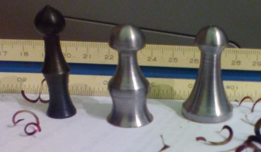
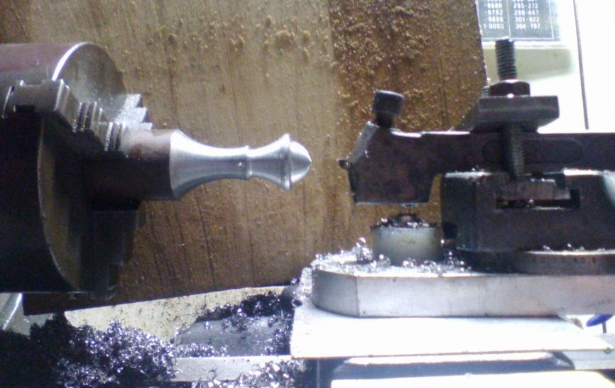
                              In order to understand how they work I've been doing some doodling using the ball cutter linked below, having a go at making chess pieces. Its been very interesting cutting bobbles on the end, and coves into the sides of the pieces with the pivot point well outside the workpiece. Cannot figure out how to attach photos.

                              Interesting that I was able to use a shear tool to get a nice finish.

                              **LINK**

                              Bill

                              #268722
                              Frances IoM
                              Participant
                                @francesiom58905

                                Bill – it is easy just read
                                http://www.model-engineer.co.uk/forums/postings.asp?th=103028
                                the simplest thing to remember is put all the photos you want to use into your album
                                Posting google links doesn’t work for many

                                #268901
                                BW
                                Participant
                                  @bw

                                  Thanks Frances,

                                  See proof below that I understood the instructions. Blackened pawn achieved by heating and dunking in engine oil. Am always pleased and amazed when I read something, try it …………. and it works ! Yeeha

                                  3 pawns 1 blackened.jpg

                                  new holder 2.jpg

                                Viewing 15 posts - 1 through 15 (of 15 total)
                                • Please log in to reply to this topic. Registering is free and easy using the links on the menu at the top of this page.

                                Latest Replies

                                Home Forums Beginners questions Topics

                                Viewing 25 topics - 1 through 25 (of 25 total)
                                Viewing 25 topics - 1 through 25 (of 25 total)

                                View full reply list.