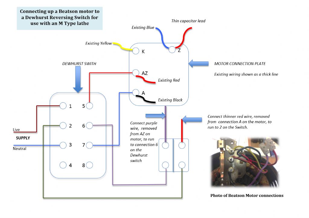
Rod, as far as I can see, that diagram id for a capacitor-start;capacitor-run motor.
Mike seems to have a capacitor-start induction motor, the nameplate give no run-capacitor value.
Mike needs to establish whether there is a centrifugal switch to work out where to go from here.
Dewhurst switches are great, but expensive and are likely overkill for reversing a single phase motor; they are more universal and are able to be used on 3 phase as well.
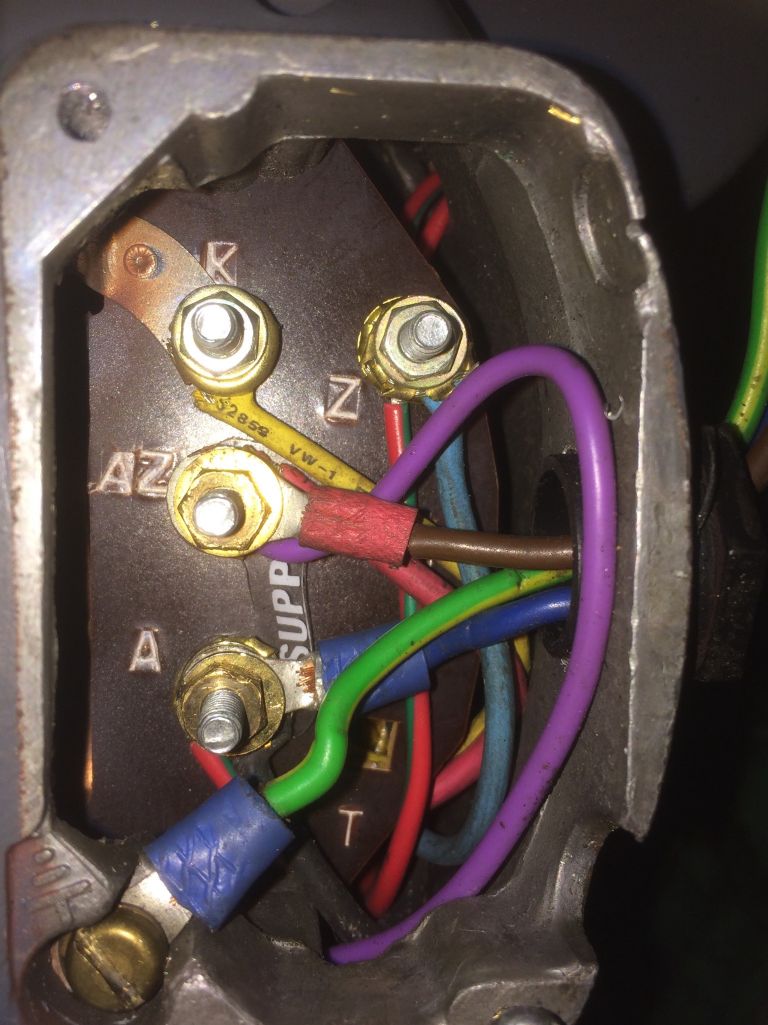
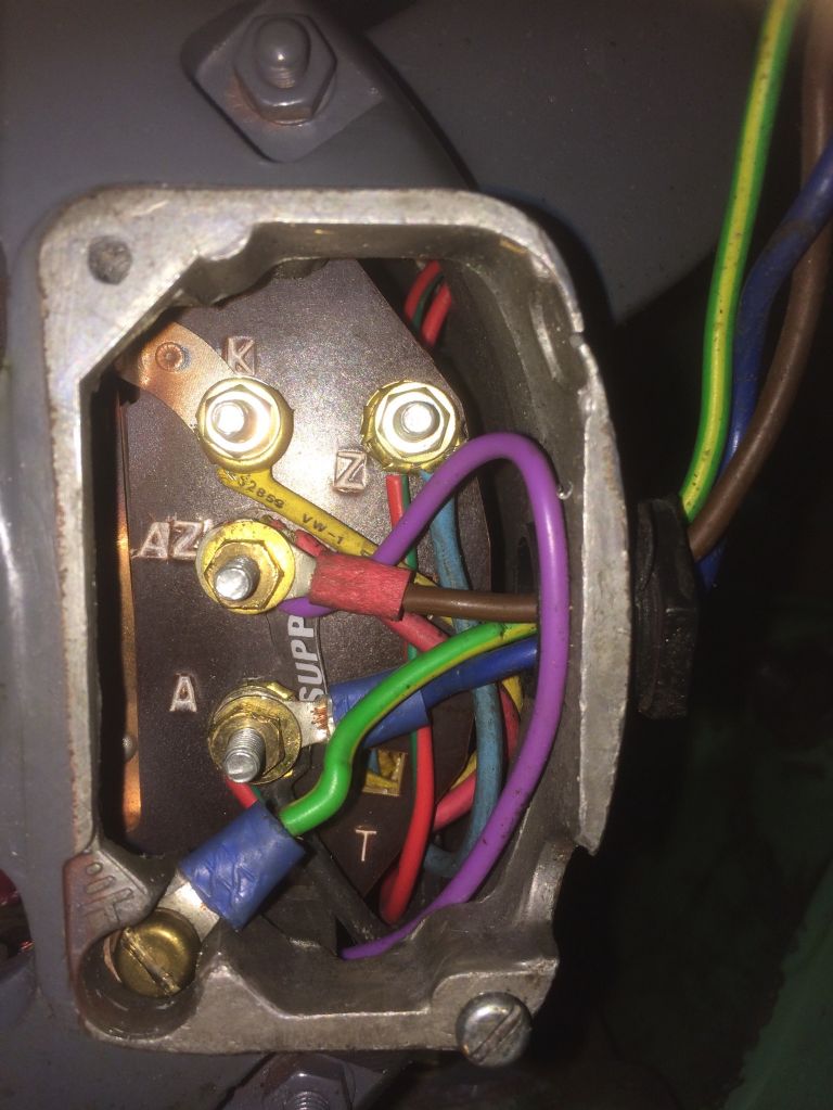
Mike has a photo of the original wiring, so disconnecting everything and measuring resistances seems the way to go, as we're not sure what a previous owner has been up to.
The start winding will have a higher DC resistance than the run winding, so it should be easy enough to ascertain the colour coding of the wires from that. It looks like there are two red/green wires, so I'm guessing they will go off to the start capacitor, or maybe a centrifugal switch if there is one.
See the second diagram on HERE for the Capacitor Start Induction Motor. Yours may or may not have a switch.
To reverse the motor, all you need to do is reverse the Start winding, which you will have already identified via your resistance meter.
This can be done with a simple Double Pole-Double Throw switch There's a nice easy diagram HERE but don't let the colours confuse you as they will be different to those in your motor.
A-AZ are likely to be the run windings. most motors I've seen have Z-T as the start windings, but this one omits T and has K instead, so I'm guessing that might be going off to one side of a centrifugal switch.
Bill
Edited By peak4 on 01/02/2019 13:29:09
john fletcher 1.


