Engineers’ Level adjustment – why 4 holes?

Advert

Engineers’ Level adjustment – why 4 holes?

Home Forums General Questions Engineers’ Level adjustment – why 4 holes?

Viewing 13 posts - 1 through 13 (of 13 total)
  • Author
    Posts
  • #486632
    Gary Brightman 1
    Participant
      @garybrightman1

      I have an 'Oxford' engineers' level similar to the Moore & Wright ELS. It has two holes/adjusters at each end (i.e. 4 in total) but the instructions don't clearly explain why there are two at each end. I'm thinking that the outer pair of holes might be locking screws and the inner ones are the actual adjusters. The instructions say not to over-loosen the outer screws as the vial could detach from the base which implies that they are locking screws but it refers to them as 'adjustment screws' which makes it rather confusing.

      Does anyone know exactly why there are two pairs of holes/adjusters and if the outer pair are actually locking screws?

      **LINK**

      Advert
      #27524
      Gary Brightman 1
      Participant
        @garybrightman1
        #486647
        Pete Rimmer
        Participant
          @peterimmer30576

          I would expect that the outside holes are threaded into the vial carrier so those screws 'pull' and the inside holes thread into the housing so they 'push', thus allowing adjustment with the facility to hold the vial very firmly. If you loosen either outside hole too much the vial carrier will fall off the screw.

          #486648
          David Davies 8
          Participant
            @daviddavies8

            Gents

            I have a M & W ELS in bits in front of me. I still haven't got round to replacing the vial though I have obtained a spare vial. The outer screws hold the vial carrier to the level frame. The heads of the inner screws are beneath the vial carrier and 'jack' the carrier away from the frame..

            Both bottom holes in the vial carrier are clearance holes, only the frame is tapped.

            The replacement vial was obtained from Cromwell tools. (I have no connection)

            HTH

            Dave

            #486775
            Gary Brightman 1
            Participant
              @garybrightman1

              Many thanks for the replies. So, if my understanding is correct (and the screws are normal R/H thread), the adjustment procedure would be…

              1. Loosen both outer screws a small amount.

              2. Perform the required adjustment using the inner screws (unscrew to raise vial holder that side).

              3. Tighten the outer screws and re-check the calibration.

              4. Repeat 1 – 3 as necessary.

              Gary

              #486788
              Rod Renshaw
              Participant
                @rodrenshaw28584

                Yes, and quite a lot of repeats in my experience!

                Rod

                #486800
                David Davies 8
                Participant
                  @daviddavies8

                  Gary

                  at the risk of me stating the obvious the level must be swapped end for end on your reference surface after each iteration. The reference need not be level but the bubble must be in the same position for both orientations.

                  regards

                  Dave

                  #486812
                  Gary Brightman 1
                  Participant
                    @garybrightman1

                    Hi Dave, I didn't mention the 'swapping ends' bit in my original post as I didn't want to complicate the message but I do understand the process and I have a good surface plate. It was purely the arrangement of the screws in the four holes that I didn't get as it isn't explained properly in the instructions.

                    Gary

                    #487317
                    Mike Donnerstag
                    Participant
                      @mikedonnerstag

                      Thanks chaps – I bought a second-hand Moore & Wright ELS recently without instructions and, of course, it needed adjustment. I rang Bowers Group (who I understand own M&W) who told me that it was not possible to adjust it and there was no repair service! Not very helpful at all!! A good case of management too far removed from the manufacturing – they knew nothing about the product at all. I found through trial and error that the inner screws were there for adjustment, though I didn't know that the outer screws needed tightening afterwards, so I've learnt something there.

                      Mike

                      #487325
                      Martin Connelly
                      Participant
                        @martinconnelly55370

                        I suspect the original production would have been set up with a calibrated low torque driver and a good reference surface to allow consistency in adjustment so making it easier. Variation in applied torque when tightening the outer screws will have you chasing your tail.

                        Martin C

                        #487344
                        john fletcher 1
                        Participant
                          @johnfletcher1

                          i had a similar experience to Mike when I phoned Tyco Brook / Crompton motor at Doncaster, regarding a motor internal connection. The motor was before me and had the data plate details as well, the person said we didn't make those motor, strange old world. Several years ago I had a slight problem with an Omeron inverter, the technical guys there were just so helpful pleased to say. John

                          #487380
                          Gary Brightman 1
                          Participant
                            @garybrightman1

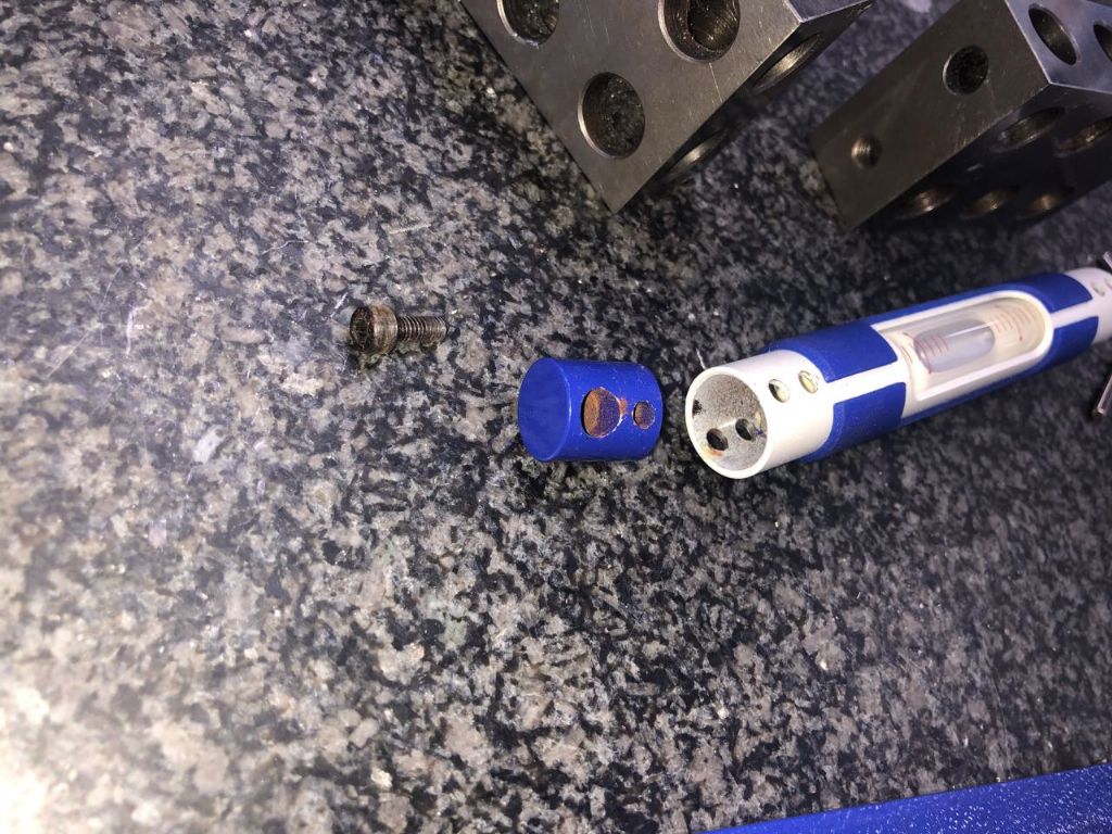
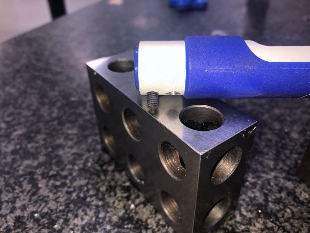
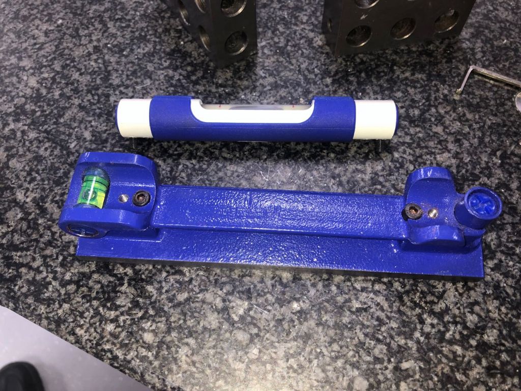
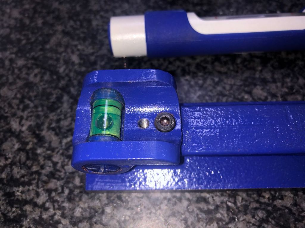
                            So my curiosity got the better of me and I took the thing apart to see for myself what is going on inside. I have to admit that I'm not overly impressed with the construction and quality of the machining…….what was I expecting for less than £100?

                            The vial is held in an aluminium tube that has some form of external paint finish and this bears onto the heads of the 'adjusting' screws that appear to be fairly standard hex headed machine screws. Quite crude really!

                            So here's a few shots of the innards…..

                            img_4216.jpgimg_4215.jpg

                            img_4213.jpg

                            img_4214.jpg

                            #487393
                            Baz
                            Participant
                              @baz89810

                              Looks crude but obviously works, cannot think of a more elegant way of doing it without costing a lot of 💰

                            Viewing 13 posts - 1 through 13 (of 13 total)
                            • Please log in to reply to this topic. Registering is free and easy using the links on the menu at the top of this page.

                            Advert

                            Latest Replies

                            Home Forums General Questions Topics

                            Viewing 25 topics - 1 through 25 (of 25 total)
                            Viewing 25 topics - 1 through 25 (of 25 total)

                            View full reply list.

                            Advert

                            Newsletter Sign-up