Drummond / Myford M Headstock Bearing

Advert

Drummond / Myford M Headstock Bearing

Home Forums General Questions Drummond / Myford M Headstock Bearing

Viewing 25 posts - 1 through 25 (of 45 total)
  • Author
    Posts
  • #295467
    James Jenkins 1
    Participant
      @jamesjenkins1
      Hi all,
       
      I have eventually got around to putting the flat belt pulleys in my longbed Myford M, so that I can replace the standard Drummond one on the treadle stand.
       
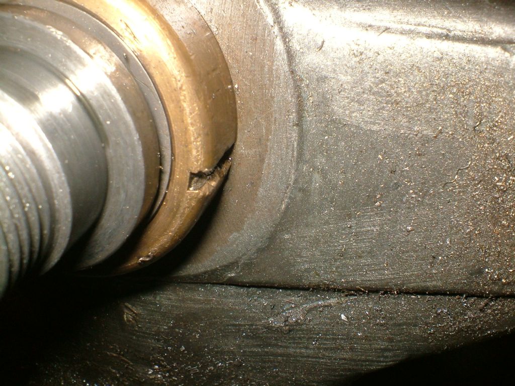
      I have got the headstock apart and removed the thrust bearing from from behind the left hand bronze bearing. However, on inspection the trust bearing case has been crushed somewhat on one inner edge, trapping three of the balls which now have flats on them. Clearly this was not the right bearing for the job, but obviously I don't really know what the correct one is. It's been suggested that a roller bearing such as this one: **LINK** would be a good fit?
       
      Just as an aside, I see that some people use two thrust bearings. Not found definite information on this – such as where the second one goes, but it seems to be quite popular
       
      Any advice?
       
      Kind regards,
       
      James
       
      MABEL & CO
       
      Establishing an organic tweed weaving studio on the Suffolk Coast.
       
      Follow our progress: Facebook and Instagram

      Edited By James Jenkins 1 on 29/04/2017 10:41:13

      Advert
      #25208
      James Jenkins 1
      Participant
        @jamesjenkins1
        #295486
        geoff walker 1
        Participant
          @geoffwalker1

          Hi James

          Go to the simplybearings.co.uk website

          The bearing you need is FT 3/4 Imperial thrust bearing 3/4 x 1.313 x 0.281.

          This bearing is the same size as the original drummond spindle thrust bearing.

          I would recommend adding the extra bearing as this eliminates end float of the spindle.

          For details of this bearing and how to fit it go to the drummond user site and in the files look up "Eugenes bearing dodge".

          Eugene explains in detail what to do and gives you the part number for the additional bearing, also supplied by simply bearings.

          Hope this helps geoff

          #295661
          David George 1
          Participant
            @davidgeorge1

            Hi James

            I have done the Mod and fitted the extra thrust bearing NTA1625-TRA1625 from Simply Bearings and it is as straight forward as just fitting it between the bronze bush and spindle at the chuck end as it fits straight into the recess.

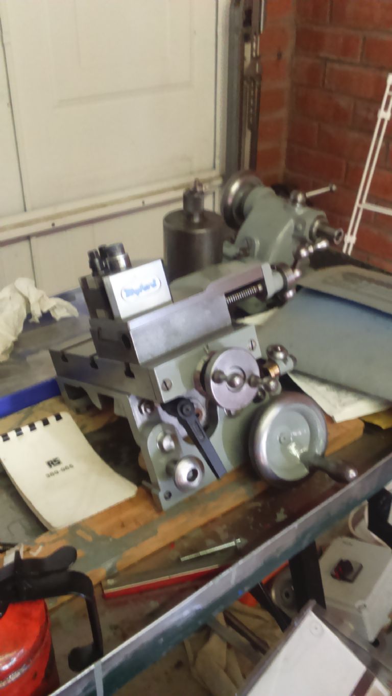
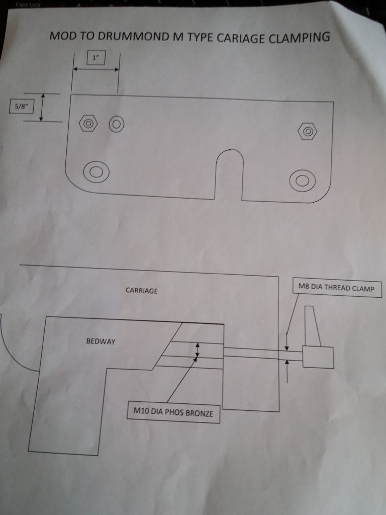
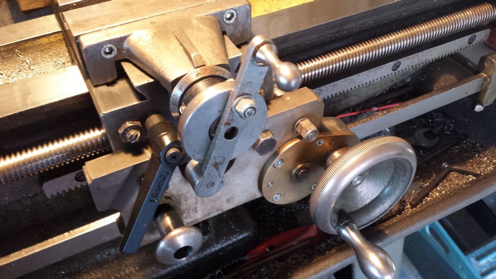
            I have also done a few other mods like a quick change toolpost and a proper saddle clamp which clamps the saddle to the main way and not pull the saddle to the rear if you use the bolts to the back of the saddle. see attached pictures and if you look in my album there are some other pictures etc. And if you want any further information send me a PM.

            David

            slideway clamp 3.jpg

            Myford Lathe

            slideway clamp 4.jpg

            #295674
            geoff walker 1
            Participant
              @geoffwalker1

              Hi David/James,

              David I am intrigued by your bearing mod. The early drummond m types (1921-24) had the spindle thrust bearing at the chuck side of the right hand main bearing behind the flange on the spindle, so nothing unusual in your mod.

              I assume you have omitted the original thrust bearing which locates on the spindle on the inside of the left hand main bearing. Would that be right as it would seem impossible to adjust both bearings simultaneously when tightening the adjustment nut on the end of the spindle? Or am I missing something?

              The saddle lock looks good, the rear saddle lock can be pain to use especially when the cross slide is in overhanging at the rear. Can you add some more details to your sketch? Is the lever connected directly to the bronze bush?

              cheers geoff

              #295715
              David George 1
              Participant
                @davidgeorge1

                Hi Geoff

                I kept the original thrust bearing in place as when I checked the clearance it was an exact gap size for the new bearing only giving two or three thousands of nip on the new bearing. Also the handle for the saddle lock is not connected directly to the bronze clamp, angled and a slide fit but it is just a length of screwed rod inserted into a indexable handle so that you can position the handle where you like radially. Bought from ARC EUROTRADE part No 084-013-00063.

                David

                #295780
                geoff walker 1
                Participant
                  @geoffwalker1

                  Thank you David,

                  That's good information. I intend to service the headstock this summer so I will see if your mod can be done on my M type. Always thought it was logical to have the main spindle thrust bearing as close to the business end as possible.

                  Just ordered a handle from arc euro, definitely do that this summer as well.

                  cheers geoff

                  #295989
                  Ady1
                  Participant
                    @ady1

                    I got both front and rear this AM for less than 20 delivered from simply bearings

                    Might be a while before I fit them but well worth doing if you plan on hanging on to your Drummond M series for future years

                    #296395
                    James Jenkins 1
                    Participant
                      @jamesjenkins1

                      Hi all,

                      I am so sorry, I always click "Email me replies" and as nothing had come through assumed that no-one had any experience of this. All very helpful information – so thank you!

                      I struggle to get on to the Drummond Group website, although I am an email member. However, it seems very simple, so hopefully I can do it without needing to.

                      As I say, apologies for the slow reply and thanks for all the info.

                      James

                      #296464
                      Ady1
                      Participant
                        @ady1

                        Arrived today, fitted it tonight, (boys and their toys eh) only used very mild preloading which I presume is correct

                        Runs smoother but the real test will come later when I put it through its paces

                        edit: the back of my spindle shoulder is not square , it's slightly tapered so all the loading is going up through the thrust washer from its internal diameter point to the rollers, I would prefer it if the shoulder was square but we shall see

                        The rear bearing uses a similar system, but with a much thicker washer which is less prone to distortion under load

                        Edited By Ady1 on 05/05/2017 03:21:33

                        #296490
                        Ady1
                        Participant
                          @ady1

                          Chucked a bit of 15mm and took rough 0.5 mm cuts with ease, there is a noticeable increase in the amount of power available for the cut with this mod, I'm a happy bunny.

                          #296508
                          James Jenkins 1
                          Participant
                            @jamesjenkins1

                            Hi all,

                            This all sounds very good, so excuse my slowness but if I am reading it correctly:

                            NTA1625-TRA1625 on the inside of the bronze bearing at the chuck end, between bronze bearing and the back gear plate (with the main shaft through).

                            NTA1220-TRA1220 on the inside of the bronze bearing at the change wheel end, between bronze bearing and the main drive pulley (again with the main shaft through).

                            Is this correct?

                            James

                            #296525
                            geoff walker 1
                            Participant
                              @geoffwalker1

                              Hi James,

                              On my lathe I have the standard original thrust bearing and an additional needle roller thrust bearing. Replacement for the standard bearing from simply bearings is FT 3/4 imperial thrust bearing. (0.75 x 1.313" x 0.281&quot

                              The needle roller bearing is fitted on the spindle on the left hand side of the left hand main bearing, (gear train end). The part number for this bearing from simply bearings is NTA1220 with 2 TRA1220 washers. (0.75" x 1.25" x 0.1381&quot.

                              With both bearings in place it can be seen that by by tightening the adjustment collar you will simultaneously adjust both bearings. They can be lightly loaded to eliminate any end float of the spindle which is the reason for fitting the additional bearing. End float is common cause of "tool chatter" so eliminating it is clearly a good idea.

                              David's idea was to add an additional bearing at the front. I have no experience of this mod so I am unable to comment. I can say that my mod (Eugene's idea) is certainly worth doing and improves stability.

                              cheers geoff

                              #296534
                              Ady1
                              Participant
                                @ady1

                                NTA1625-TRA1625 on the inside of the bronze bearing at the chuck end, between bronze bearing and the back gear plate (with the main shaft through).

                                No, it goes on the thrust side, which is on the outside of the bearing housing at the chuck end, between the rear shoulder of the spindle nose and the castellated nut

                                #296628
                                Hopper
                                Participant
                                  @hopper
                                  Posted by Ady1 on 05/05/2017 14:58:17:

                                  NTA1625-TRA1625 on the inside of the bronze bearing at the chuck end, between bronze bearing and the back gear plate (with the main shaft through).

                                  No, it goes on the thrust side, which is on the outside of the bearing housing at the chuck end, between the rear shoulder of the spindle nose and the castellated nut

                                  You might want to put a cover over it to keep swarf out in that zone. I made such a cover for mine, just to keep oil from flinging out everywhere, out of the top section of a stainless steel solar garden light. Pushes right on over the castelated nut and has a solid end that I bored to fit the boss on the chuck back plate. Not a hermetic seal but stops flying oil and debris for the most part.

                                  One of these from the local hardware shop for two dollars. The top piece is the exact size to push firmly over the castellated nut. Then bore a hole straight through the solar cell unit on the top to fit the spindle nose/chuck boss.

                                  #297228
                                  Ady1
                                  Participant
                                    @ady1

                                    It's made quite a difference to the chuck stiffness and the amount of power to the cut, vibration only seems to come from the tool itself if I push too hard

                                    This one has other possibilities if you have "a machine tool that turns" IMO

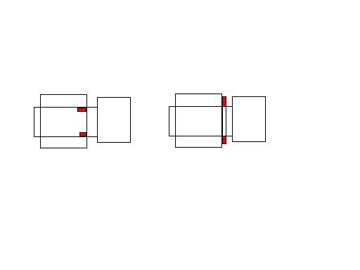
                                    This kind of Mod can improve the performance of any spindle on any machine if you can fit it, I think it could be because it moves the levering action further away from the centreline of the spindle, giving you the performance of a bigger spindle size, as shown by the right hand diagram

                                    bearing mod.jpg

                                    I'm thinking in particular if you wanted to make a small milling attachment for a lathe cross slide, theoretically this kind of mod could seriously improve performance

                                    Edited By Ady1 on 09/05/2017 01:34:26

                                    #297230
                                    Hopper
                                    Participant
                                      @hopper
                                      Posted by Ady1 on 09/05/2017 01:14:23:

                                      It's made quite a difference to the chuck stiffness and the amount of power to the cut, vibration only seems to come from the tool itself if I push too hard

                                      This one has other possibilities if you have "a machine tool that turns" IMO

                                      This kind of Mod can improve the performance of any spindle on any machine if you can fit it, I think it could be because it moves the levering action further away from the centreline of the spindle, giving you the performance of a bigger spindle size, as shown by the right hand diagram

                                      Ady, can you post a pic of how you have done this? I'm trying to get my head around how the thrust bearing flat washer sits on the castellated nut and can't quite picture it. (As Curly from the Three Stooges said "I tried thinking about it but nuttin' happened&quot

                                      #297232
                                      Ady1
                                      Participant
                                        @ady1

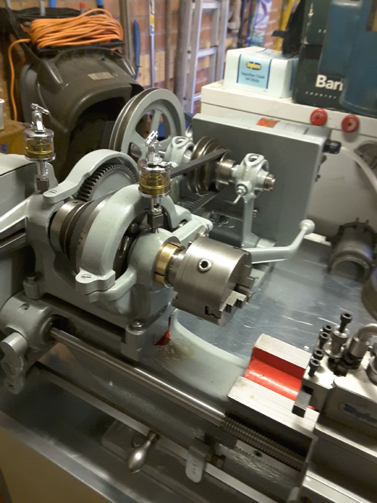
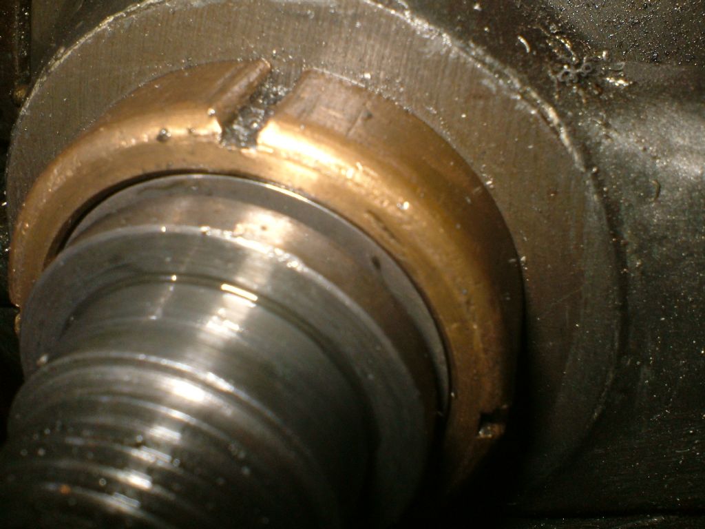
                                        It's the bit of metal behind the spindle shoulder and fits quite beautifully into the recess of the castellated nut

                                        dscf3085.jpg

                                        dscf3089.jpg

                                        #297233
                                        Ady1
                                        Participant
                                          @ady1

                                          I've bought another front bearing tonight btw, this has legs if you're a drummond dude

                                          The front washer is tight on the spindle because the spindle tapers slightly towards the back of the spindle nose, this helps to transfer the load of the cut to the roller bearing sitting behind it

                                          For an off-the-shelf bearing it's an amazing fit

                                          Edited By Ady1 on 09/05/2017 02:09:22

                                          #297261
                                          Ady1
                                          Participant
                                            @ady1

                                            Perhaps it allows a higher pre-load between the two headstock housings, the original setup had the spindle simply sticking out of the front bearing and all the roller bearing work being done at the back.

                                            #297271
                                            Hopper
                                            Participant
                                              @hopper

                                              Aah, CLUNK, penny drops. The bearing fits inside the nut and bears on the nice flat end of the actual bronze bearing. Looks like a nice fit.

                                              Although, that would put axial cutting forces on to the tapered bronze bearing, pushing in the direction to loosen the bearing in the taper and the end loading would be taken by the threads on the end of the bearing and the castellated nut. Will be interested to see how they stand up over time.

                                              Taking .5mm cuts? Mine will take .100" cuts (2.5mm) with the standard thrust bearing all day long without drama. So maybe the extra thrust bearing is making up for some other wear on your lathe? I do keep my headstock bearings good and tight (just free to turn) and bed is in very good nick. Maybe I am lucky with this old machine.

                                              #297296
                                              geoff walker 1
                                              Participant
                                                @geoffwalker1

                                                Hi All,

                                                Yes, this mod of David's is interesting.

                                                I have a spare headstock, spindle, bearings etc. and have been experimenting.

                                                The first thing I notice is that with the new chuck end R.H. thrust bearing in place the spindle is moved outwards a small amount. The effect of this is that it is impossible to correctly adjust the original L.H. thrust bearing unless you insert a shim washer in between the the outer ring of the bearing and the shoulder on the L.H. end of the spindle. This is not a problem as the washer could be ground accurately to fit the gap

                                                For this mod I would first of all square off the inside of the spindle on the chuck end shoulder( I know a bold step! )so the bearing lies flat against the shoulder. It is also important that when tightening the adjustment ring on the L.H. end of the spindle that both bearings adjust, "pinch", simultaneously, which is difficult to achieve but not impossible. This setting must be done with both front and rear main bearings correctly adjusted for use and locked in their working LATERAL positions.

                                                Just my thoughts geoff

                                                #297440
                                                Ady1
                                                Participant
                                                  @ady1

                                                  I hadn't actually fitted the rear bearing, only the front one, you need to remove the backgear to do the rear one and my original one was fine the last time I checked.

                                                  Anyway, in a moment of lucidity, or madness, I decided to remove the rear washer and fit this bearing right at the back yesterday.

                                                  So now my spindle is suspended between two roller bearings (light/medium preloading) and the main bearings can still be adjusted no problem

                                                  Makes a nice whirry noise as it runs…

                                                  Edited By Ady1 on 10/05/2017 11:18:43

                                                  #297473
                                                  geoff walker 1
                                                  Participant
                                                    @geoffwalker1

                                                    Hi Ady,

                                                    Yes I plan to fit the new end bearing as well, still needed to eliminate any end float of the spindle.

                                                    Having you try this as well. David's saddle lock, just the job and a few hours work.

                                                    Nice one David, thank you for the photo and info.

                                                    No more leaning over the machine to lock the saddle!!!! hooray.

                                                    geoffsaddle lock M type lathe

                                                    #359204
                                                    James Jenkins 1
                                                    Participant
                                                      @jamesjenkins1

                                                      Hi all,

                                                      I have been scratching and scratching my head over this. I ordered the bearings and then was looking again and again at the pictures and yet only just in the last few minutes have I realised what I have done. So there are two options for the new thrust bearing and I have ordered the bearings for one and trying to fit it as though the other!

                                                      Please excuse the rough and ready drawing below, redrawn from the Drummond Manual. Am I correct in thinking there are two options for the new thrust bearing? Both outlined below? If so, is there a recomended one or is it a matter of opinion? Is a Myford M the same design?

                                                      Many thanks and I think I might be close to solving this!

                                                      James

                                                    Viewing 25 posts - 1 through 25 (of 45 total)
                                                    • Please log in to reply to this topic. Registering is free and easy using the links on the menu at the top of this page.

                                                    Advert

                                                    Latest Replies

                                                    Home Forums General Questions Topics

                                                    Viewing 25 topics - 1 through 25 (of 25 total)
                                                    Viewing 25 topics - 1 through 25 (of 25 total)

                                                    View full reply list.

                                                    Advert

                                                    Newsletter Sign-up