Digital CNC phase converter build

Advert

Digital CNC phase converter build

Home Forums The Tea Room Digital CNC phase converter build

Viewing 19 posts - 26 through 44 (of 44 total)
  • Author
    Posts
  • #554962
    John Haine
    Participant
      @johnhaine32865
      Posted by Andrew Johnston on 20/07/2021 19:54:59:

      Super yachts have power converters that take shore power from anywhere in the world and generate clean 3-phase for distribution around the yacht. Here's an example:

      Shore Power Converter

      I don't own a super yacht, so don't know how much they cost.

      Andrew

      Anything for yachts is automatically more expensive. As the saying goes, if you have to ask the price, you can't afford it! And: sailing can best be described as standing under a cold showevr tearing up fifty pound notes…

      Advert
      #554964
      Anonymous

        Posted by Bob Worsley on 20/07/2021 20:03:53:

        ………..A 100A 400V 3ph supply is about 24kW………

        A 100A 3-phase supply is 100A per phase, so 3x240x100=72kW.

        Andrew

        #554969
        Robert Atkinson 2
        Participant
          @robertatkinson2
          Posted by Robert Laurenson on 20/07/2021 20:04:25:

          Hi Robert,

          Speaking with Phase Perfect just now, and they can supply it as 50hz, so no issue there.

          And i will have to run it through a transformer anyway due to the 480v, i need it down at 440 ish to run my equipment.

          To be honest i do think now that its the only way to go.


          Make sure your electrician and supply company are happy with it before you spend the money. It has NO UK / EU approvals at all. That means it may not be legal to use. I'm not sure what the current requirements for fixed industrial electrical equipment are. If it is a non-industrial installation it has to be approved equipment.

          Robert G8RPI.

          Edited By Robert Atkinson 2 on 20/07/2021 21:11:50

          #554970
          Robert Laurenson
          Participant
            @robertlaurenson59999
            Posted by Robert Atkinson 2 on 20/07/2021 21:11:15:

            Posted by Robert Laurenson on 20/07/2021 20:04:25:

            Hi Robert,

            Speaking with Phase Perfect just now, and they can supply it as 50hz, so no issue there.

            And i will have to run it through a transformer anyway due to the 480v, i need it down at 440 ish to run my equipment.

            To be honest i do think now that its the only way to go.

            Make sure your electrician and supply company are happy with it before you spend the money. It has NO UK / EU approvals at all. That means it may not be legal to use. I'm not sure what the current requirements for fixed industrial electrical equipment are. If it is a non-industrial installation it has to be approved equipment.

            Robert G8RPI.

            Edited By Robert Atkinson 2 on 20/07/2021 21:11:50

            Hi again,

            It is (if i buy it) being installed in an industrial unit, so should be ok from that side of things.

            Just have to wait and see, ill mull it over a while yet.

            Thanks

            Robert

            #554979
            Stuart Smith 5
            Participant
              @stuartsmith5

              Robert

              As someone who worked for over 40 years as an electrical power engineer for my local DNO ( or electricity board as it used to be), I would suggest you check with SSE to see what load and motor starting currents you can take from your existing supply. As per my post in your previous thread on buying a lathe:

              ”Robert

              Although the fuse carriers on your main DNO fuses may be labelled as 100A , you would be advised to check what current you can actually take from the network. I used to work at Electricity North West and the maximum supply capacity there was specified as 20kVA for a single phase supply ( ie 80A). The other issue may be that the rating of the pole mounted transformer may be a limiting factor. Also there are limits on voltage fluctuations caused by motor starting currents or welders (see ENA ER P28).

              Stuart”

              Regarding the ‘Phase Perfect’ – it seems to be anything but perfect.

              It is clear from the diagram in this document

              https://www.phasetechnologies.com/downloads/New_Phase_Perfect_Specifications.pdf 

              that the two existing phases are used as they are and the third phase is generated electronically. So the two phases will be 180 degrees apart and presumably the extra phase will be 90 degrees from them. The phase to phase voltages will be as per the supply (ie somewhere in the 450 to 500 volt range depending on the loads on the network etc)

              Stuart


              Edited By Stuart Smith 5 on 20/07/2021 22:20:09

              Edited By Stuart Smith 5 on 20/07/2021 22:20:59

              #554980
              Robert Laurenson
              Participant
                @robertlaurenson59999
                Posted by Stuart Smith 5 on 20/07/2021 22:10:13:

                Robert

                As someone who worked as an electrical power engineer for my local DNO ( or electricity board as it used to be), I would suggest you check with SSE to see what load and motor starting currents you can take from your existing supply. As per my post in your previous thread on buying a lathe:

                ”Robert

                Although the fuse carriers on your main DNO fuses may be labelled as 100A , you would be advised to check what current you can actually take from the network. I used to work at Electricity North West and the maximum supply capacity there was specified as 20kVA for a single phase supply ( ie 80A). The other issue may be that the rating of the pole mounted transformer may be a limiting factor. Also there are limits on voltage fluctuations caused by motor starting currents or welders (see ENA ER P28).

                Stuart”

                Regarding the ‘Phase Perfect’ – it seems to be anything but perfect.

                It is clear from this diagram that the two existing phases are used as they are and the third phase is generated electronically. So the two phases will be 180 degrees apart and presumably the extra phase will be 90 degrees from them. The phase to phase voltages will be as per the supply (ie somewhere in the 450 to 500 volt range depending on the loads on the network etc)

                Stuart

                Hi Stuart,

                Thanks for the reply,

                Ive spoken to them and they said max 48kva, 75kva transformer on the pole.

                They also said the cable they installed to my premesis is big enough they could double it to 100kva split phase. (with a transformer upgrade)

                The equipment im looking at, the only big motor is the press brake, but its a soft start servo motor so that shouldnt be an issue either as far as start surge goes.

                The phase perfect, that bit you said about 180 degrees is exactly what i thought. Looking at forums, it seems to not be correct. Found a video online showing an oscilloscope monitoring one under several load conditions and the phases being perfectly balanced.

                The 480v output seems to be the only issue and the lack of Neutral. So i have got a couple of quotes for a delta to star isolation transformer to step down the voltage and give me a neutral. By the sounds of it it will work.

                Again regarding the 180 degrees apart bit i saw an analogy which someone wrote under the video of the PP sine wave monitoring.

                They said something along the lines of this.

                If you put 3 stakes in the ground as an equilateral triangle, if you stand between two posts they are 180 apart and the other is at 90, if you stand next to a single post the otber two are at 60, and in the middle they are all at 120. Said he was an electrical engineer and had a PP system running all kinds a stuff from a cnc lathe to other things. Not sure if what he said is right, but it makes sense in simple terms. If i were to use a rotary converter i would still be putting the two 240 legs in and making the 3rd, so its just a digitally balanced version of the same is it not?

                #554984
                Stuart Smith 5
                Participant
                  @stuartsmith5

                  Robert

                  Yes, I was thinking of the voltages and phases measured to the existing neutral. I can see that for a delta connected supply, it would work as you say, so your idea of a delta/ star connected transformer would give a neutral and correct the voltages.

                  Regarding the supply capacity, as well as the kVA rating there is also the effect of any sudden changes in load such as welders and motors. Your DNO may have already told you what maximum welding and motor starting currents you can have. There is an Energy Networks Association (ENA) document Engineering Recomendation P28 which DNOs use to calculate these figures ( though they may have their own policies based on this).

                  **LINK**

                  Stuart

                  Edited By Stuart Smith 5 on 20/07/2021 22:57:59

                  Edited By Stuart Smith 5 on 20/07/2021 22:59:02

                  #554993
                  Robert Laurenson
                  Participant
                    @robertlaurenson59999
                    Posted by Stuart Smith 5 on 20/07/2021 22:54:26:

                    Robert

                    Yes, I was thinking of the voltages and phases measured to the existing neutral. I can see that for a delta connected supply, it would work as you say, so your idea of a delta/ star connected transformer would give a neutral and correct the voltages.

                    Regarding the supply capacity, as well as the kVA rating there is also the effect of any sudden changes in load such as welders and motors. Your DNO may have already told you what maximum welding and motor starting currents you can have. There is an Energy Networks Association (ENA) document Engineering Recomendation P28 which DNOs use to calculate these figures ( though they may have their own policies based on this).

                    **LINK**

                    Stuart

                    Edited By Stuart Smith 5 on 20/07/2021 22:57:59

                    Edited By Stuart Smith 5 on 20/07/2021 22:59:02

                    Stuart,

                    Yes the DNO said the supply was capable of direct on line starting of a 15kw load, so more than enough for what i will be doing. My welders are all new inverter type machines so no sudden surges and biggest is 300a so nothing big. Plasma the same, so i think i will be ok in that regard.

                    thanks

                    #555000
                    Stuart Smith 5
                    Participant
                      @stuartsmith5

                      Robert

                      Looks like you have it all covered.

                      Be interesting to see how the overall costs compare to having supply upgraded to 3 phase.

                      Stuart

                      #555002
                      Anonymous

                        Posted by Robert Laurenson on 20/07/2021 22:25:32:

                        If you put 3 stakes in the ground as an equilateral triangle, if you stand between two posts they are 180 apart and the other is at 90, if you stand next to a single post the otber two are at 60, and in the middle they are all at 120. Said he was an electrical engineer and had a PP system running all kinds a stuff from a cnc lathe to other things.

                        All it means is that the reference point is being moved, basic geometry. The angles change but also the magnitudes, so the system will not be balanced. Not really comparing like to like. Of course perpendicular phases may well work, depending upon the application.

                        I worked for a company where one of the electrical engineers insisted that 4000 series logic had three states, not two. He then proceded to demonstrate that soldering on a circuit that is live at 600V with a grounded tip is not a good idea. Consequently I'm a bit cynical when people state that they're X or Y, the implication being that they know what they're doing. disgust

                        Andrew

                        #555033
                        John Haine
                        Participant
                          @johnhaine32865

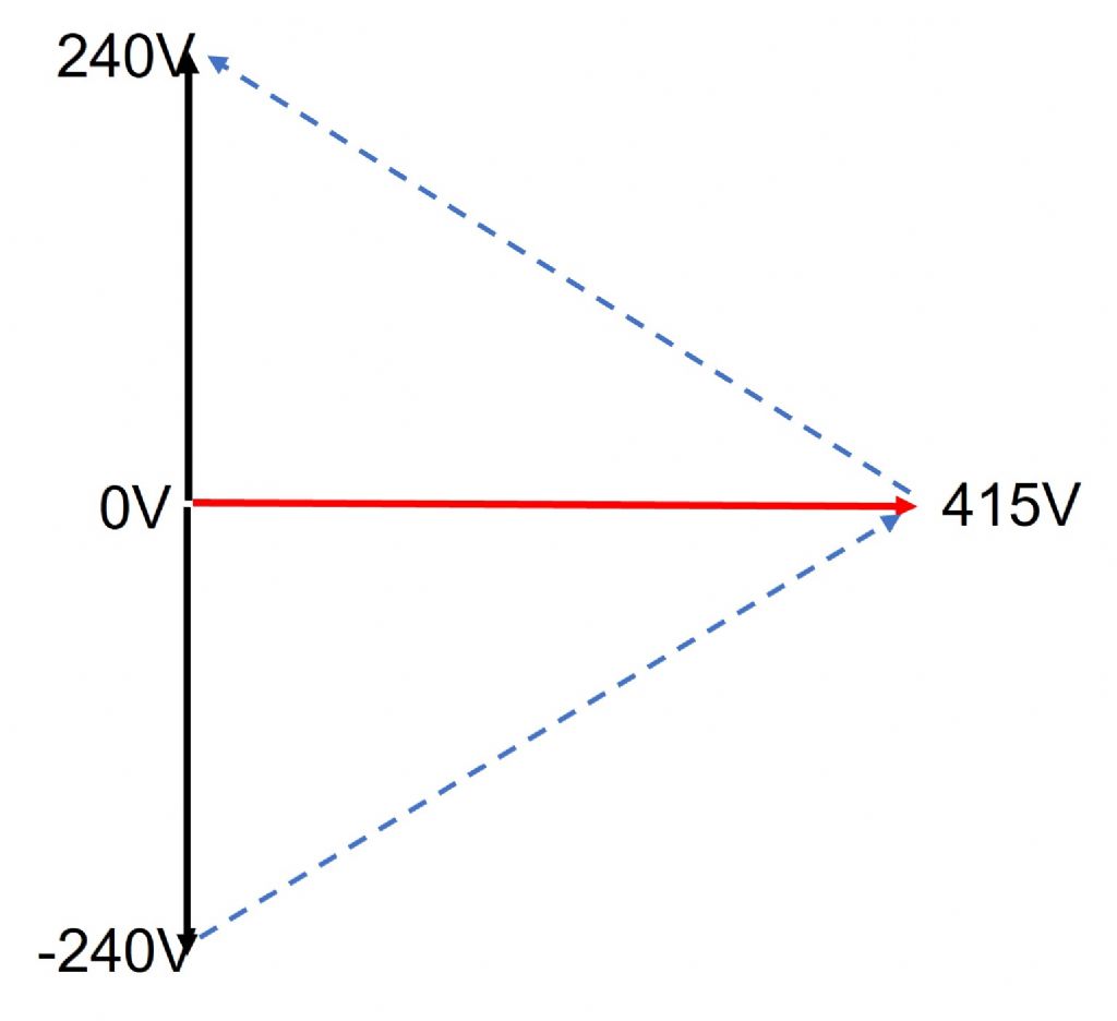
                          OK, reading the paper and thinking about this a bit more the operating principle is explained in this phasor diagram.

                          3phase.jpg

                          Here the + and -240 volt phasors are the two legs of the centre tapped mains supply (all voltages are given in RMS though strictly they should be peak). The + and – terminals of the supply become two of the phase voltages, the phase-phase voltage being 480V.

                          What the unit mainly does is via some clever power switching electronics generate a third voltage in quadrature with both and a voltage level of 415V which feeds the third phase terminal. This becomes the third phase.

                          If you now look at the phase-phase voltages and angles, they are all 480V rms and mutually at 60*, that is a true balanced 3-phase supply. Note that there is an implied "neutral" which is not at the same potential as the mains input "neutral", so you would need to be careful using the supply to machines that needed earthing for safety. This could be fixed by using a 3-phase isolating transformer with a star secondary where the star point is used as a neutral (and could be connected to mains neutral and PME).

                          It ought to be obvious that the phase and amplitude balance depends on controlling the generation of the 415V auxiliary signal to be at the right level and exact quadrature, but for a DSP this is trivial at 50/60Hz. There is no reason why the system should not generate 3 phase as accurate as a conventional VFD, with the benefit that only one power output stage is needed. 

                          The actual product, if as described in the paper, has some switched capacitor trickery to save components in the power amplifier but I think essentially follows this operating principle. I think it's rather neat!

                          Edited By John Haine on 21/07/2021 14:10:26

                          #555042
                          John Haine
                          Participant
                            @johnhaine32865

                            One might ask of course, why doesn't a conventional VFD work this way? The answer is that the system only works at the mains frequency so motor speed can't be varied.

                            #555047
                            SillyOldDuffer
                            Moderator
                              @sillyoldduffer

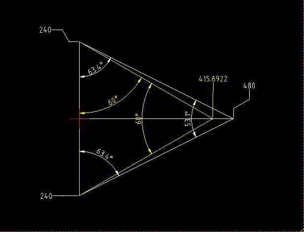
                              I'm struggling to understand, but might be nearly there! My version of John's diagram:

                              digitalphase.jpg

                              If the rightmost point of the triangle were at 480V (twice 240V), the phase angles would be two at 63.5° and one 53.1°, which is much better than an idler motor or static converter could do. The volts are balanced, but the phases are up to 6.9° out. However, if the unit reduces the output (rightmost) to 415V, as John's diagram, the phases are all balanced, at the cost of a slight voltage imbalance, also better than an idler motor or static converter.

                              Presumably the electronics could adjust the generated phase anywhere between 415 and 480V to improve either phase balance, or voltage, but not both. For example 447.8V gives two 480V phases at 61.8° and one 447.8V phase at 56.4°

                              Is that right? Doesn't seem to be covered in my manual:

                              Dave

                              #555054
                              John Haine
                              Participant
                                @johnhaine32865

                                I don't think it is! To get the value of the quadrature voltage, suppose it is V while the phase-phase voltage is 480V. Then you have a right-angled triangle with hypotenuse 480, one right-angle leg 240, while the other is V, and the angle at the upper vertex is 60*. Then the value of V must be sqrt(3) x 240 = 415.69. Voltages and phases are all correct. If the voltage was 480 as in your first assumption, then the second two phase-phase voltages would be greater than 480.

                                #555074
                                Stuart Smith 5
                                Participant
                                  @stuartsmith5

                                  I agree with John.

                                  Did a bit more thinking about it and I think if the phase to phase voltage of the existing split phase supply is 480v, the generated voltage is 416 with respect to the existing neutral.

                                  The only thing I would say is that if Robert goes down this route, the star point of his proposed delta/star transformer (ie the neutral for his 3 phase output) should be earthed separately and not connected to the existing supply neutral.

                                  Stuart

                                  #555089
                                  Robert Atkinson 2
                                  Participant
                                    @robertatkinson2

                                    Robert,

                                    I checked on the latest guidance regading approvals. If you buy this equipment from the USA YOU wuld become responsible for getting it approved to UK (UKCA mark) or for a limied time EU (CE Mark) standards. Specfically it would have to comply with the RoHS (hazardous substances), Low Voltage Directive (electrical safety) and EMC directive (interference). The cost of this would be unrealistic for a single installation. This may seem just red tape. It is possible that no one will ever question it, but like speeding without a licence, even if you are no caught, it is still illegal, dangerous and may leave you uninsured. Lowest level imact your power supplier tells you that tyou have to disconnect it. Next is it causes interference, you get fined and have to stop using it. I'll leave out the interference causing a plane crash, it's highly unlikey but emissions form power line have contributed to a commercial aircraft crash in the past. Worst, it catches fire, causes something else to catch fire or electrocutes someone. Your insurance does not payout and you get prosecuted.
                                    Not likey people will say, but this is a big unit connected to a (preumably long) power line. It could cause conducted and / or radiated emissions and harmonics that affect others. The producton of harmonics can overheat teh supply transformer or affect other users on the same supply. If your converter blows up another consumers equipment the bill could be very large.

                                    Robert G8RPI.

                                    #555146
                                    John Haine
                                    Participant
                                      @johnhaine32865
                                      Posted by Stuart Smith 5 on 21/07/2021 18:28:30:

                                      …….

                                      The only thing I would say is that if Robert goes down this route, the star point of his proposed delta/star transformer (ie the neutral for his 3 phase output) should be earthed separately and not connected to the existing supply neutral.

                                      Stuart

                                      I'm not sure this is correct. The "implied" neutral of the 3-phase from the converter is at an AC potential of 138V relative to the incoming neutral; but a 3-phase isolating transformer will have a "floating" neutral at it's star point which could be connected to the supply neutral, and for safety reasons this may be desirable.

                                      #555169
                                      Stuart Smith 5
                                      Participant
                                        @stuartsmith5

                                        John

                                        I wasn’t suggesting leaving the star point floating, but to earth it via a separate earth electrode.

                                        This would be the same as how the star point / neutral is earthed at an HV/LV transformer at a distribution substation.

                                        Probably best to leave it to whoever installs this to decide the way to do it. I am not sure if there are guides in the wiring regulations to cover this situation.

                                        Stuart

                                        #555228
                                        David Riley
                                        Participant
                                          @davidriley61024

                                          Just to add to the discussion here is a rotary convertor from Australia **LINK** .

                                        Viewing 19 posts - 26 through 44 (of 44 total)
                                        • Please log in to reply to this topic. Registering is free and easy using the links on the menu at the top of this page.

                                        Advert

                                        Latest Replies

                                        Home Forums The Tea Room Topics

                                        Viewing 25 topics - 1 through 25 (of 25 total)
                                        Viewing 25 topics - 1 through 25 (of 25 total)

                                        View full reply list.

                                        Advert

                                        Newsletter Sign-up