Colchester Student Mk1 Won’t Start

Advert

Colchester Student Mk1 Won’t Start

Home Forums Help and Assistance! (Offered or Wanted) Colchester Student Mk1 Won’t Start

Viewing 25 posts - 151 through 175 (of 797 total)
  • Author
    Posts
  • #458904
    Stuart Bridger
    Participant
      @stuartbridger82290

      The majority of threads on my 1963 Chipmaster are Unified, mostly UNC.

      Advert
      #458906
      Phil Whitley
      Participant
        @philwhitley94135

        Good point Stuart! So if it is UNF it will be 20TPI and UNC would be 13TPI, so if Richard can count the number of threads in an inch, he has it!

        Phil

        #458963
        Richard Kirkman 1
        Participant
          @richardkirkman1

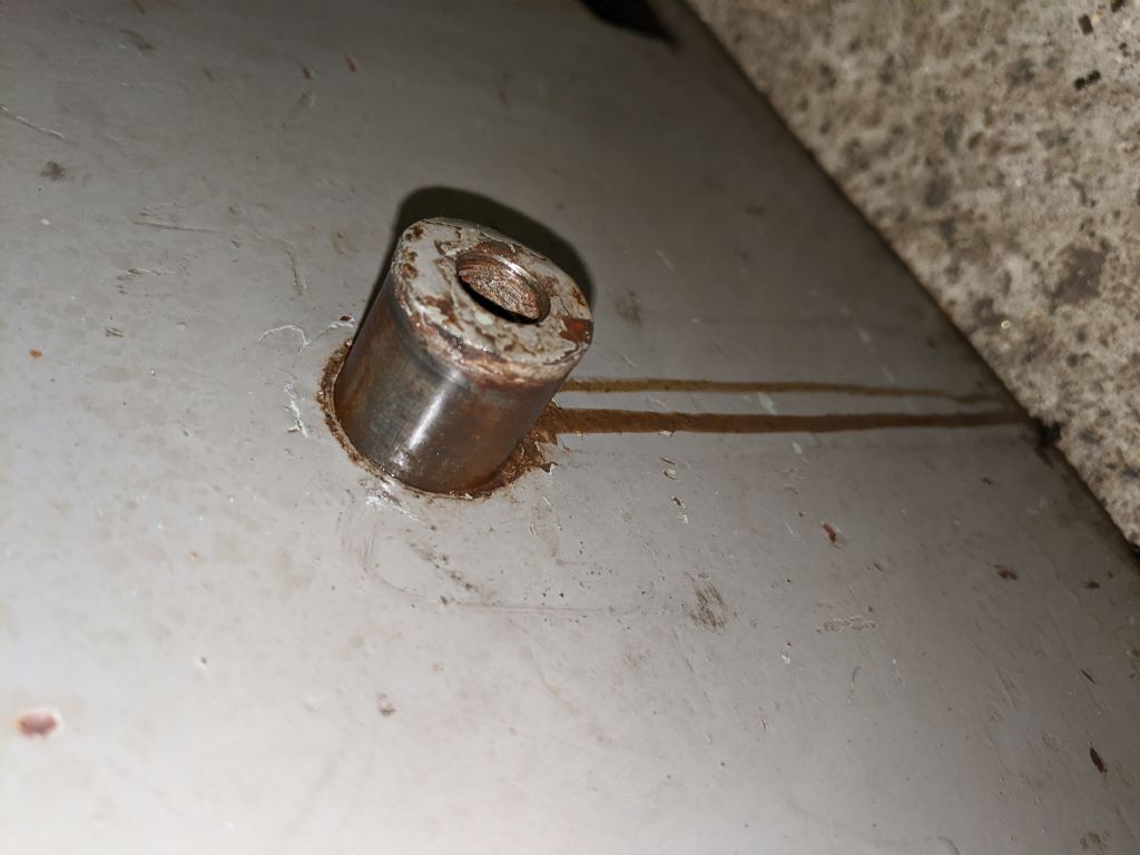
          I managed to completely avoid the thread. It seems the thread was meant to be used to pull the shaft out, but I did it another way.

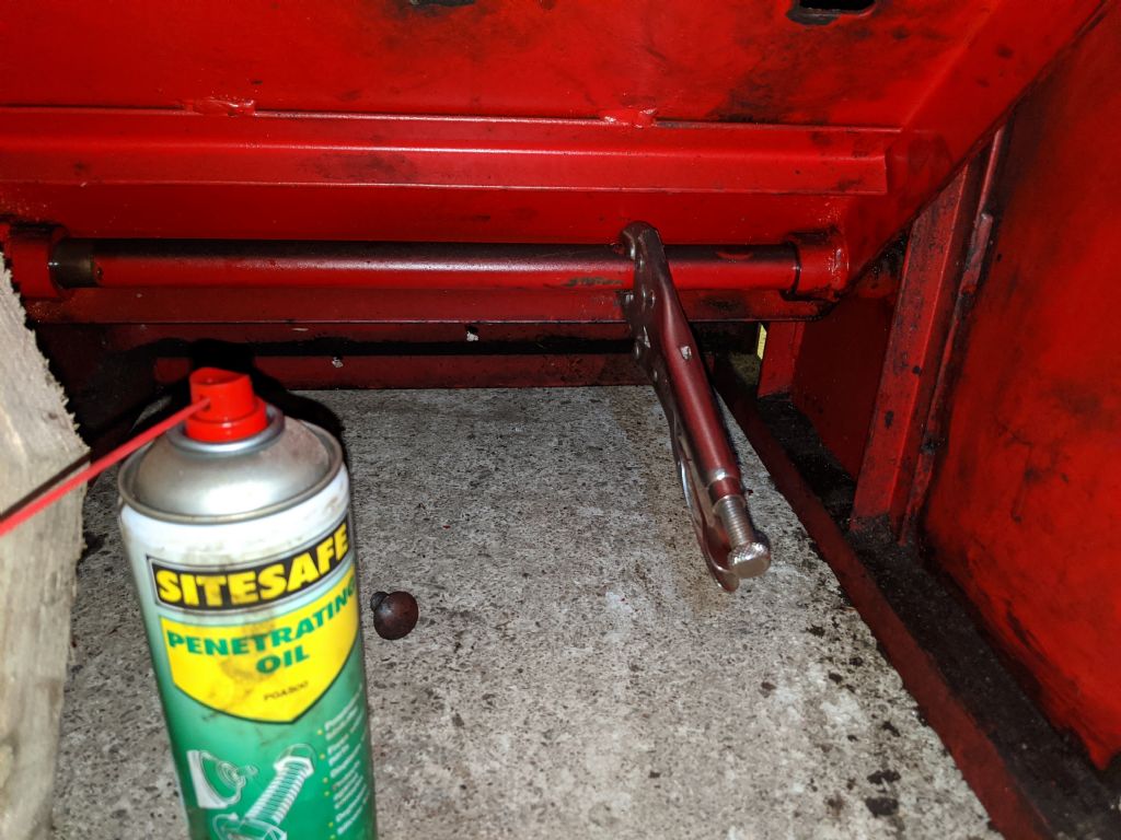
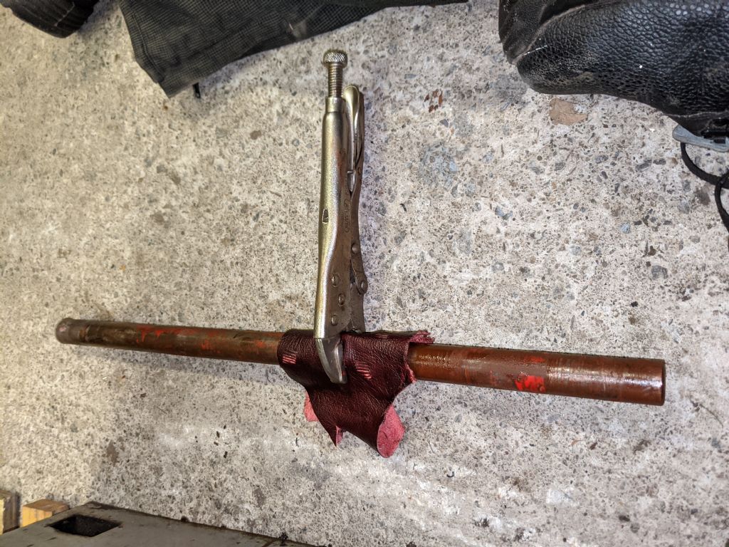
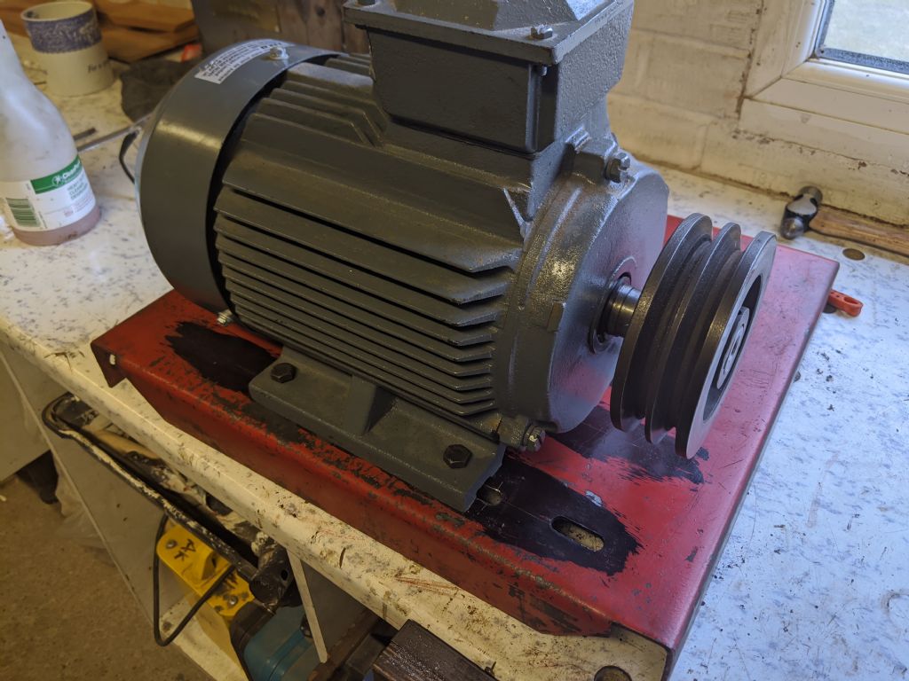
          I put lots of penetrating oil down the grub screw holes, then I attached some vice grips to the underside of the shaft, slowly starting to wiggle it bar. It took about half an hour or so, but I managed to wiggle it out eventually

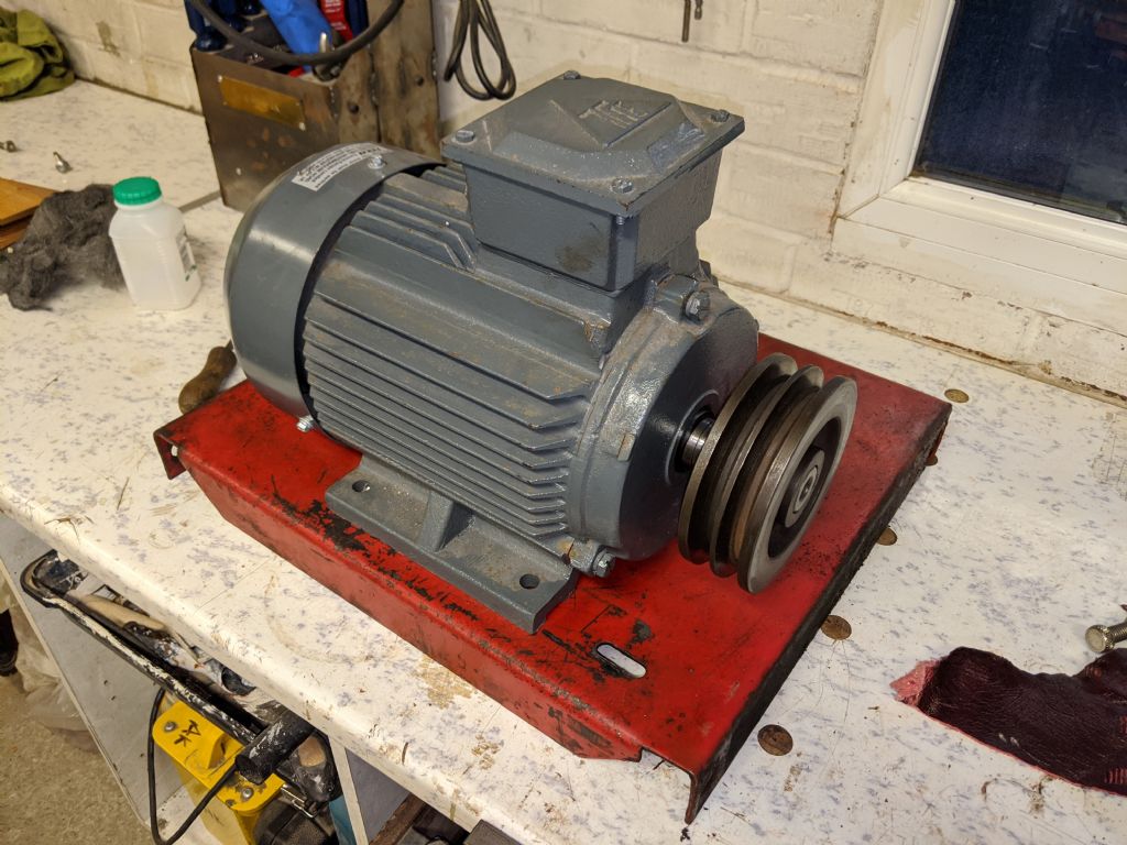
          Now I should be able to layout some marks for the new motor. I'll do that tomorrow

          Any tips for aligning the motor and laying the holes out perfectly?

          I was thinking, the old holes will be aligned properly, so if I make a centerline between each of those holes then use that line to lay everything out for, it should keep the pulley aligned? I'm just wanting to keep it square since then I can move the pulley wherever it needs to be on the shaft.

          img_20200322_182742.jpg

          img_20200322_182754.jpg

          img_20200322_184120.jpg

          img_20200322_184610.jpg

          #458969
          Howard Lewis
          Participant
            @howardlewis46836

            If you can lay a straight edge across the driven pulley, the motor should then moved to align so that the straight edge also lies across the pulley on the motor shaft.

            If all else fails, cut a bit of angle iron and clamp that to both pulleys while you drill the holes for the motor mounting bolts.

            HTH

            Howard

            #458972
            Richard Kirkman 1
            Participant
              @richardkirkman1
              Posted by Howard Lewis on 22/03/2020 20:20:35:

              If you can lay a straight edge across the driven pulley, the motor should then moved to align so that the straight edge also lies across the pulley on the motor shaft.

              If all else fails, cut a bit of angle iron and clamp that to both pulleys while you drill the holes for the motor mounting bolts.

              HTH

              Howard

              Thanks, Howard

              Problem with that is, I've taken the mounting plate out of the lathe already, and I'm quite tight on space when it's in there. I also don't have much space for marking the holes out while the motor is in place since the body lies over the holes as I cannot get a pen or marker in, nor a scribe as the casting is deeper than my scribes tip. I suppose I could make a tool

              I'll have a look at trying that tomorrow!

              Thanks!

              #459209
              Richard Kirkman 1
              Participant
                @richardkirkman1

                Good progress was made today

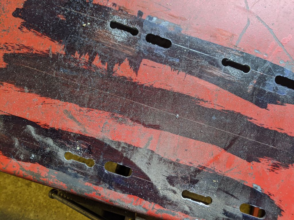
                I blued up the motor plate, marked between the old holes, then plotted my new hole locations from that line.

                I marked an inch wide slot, drilled the ends out, then used a jigsaw with a metal cutting blade to make slots, then filed the slots to size. Motor fits nicely with room for movement.

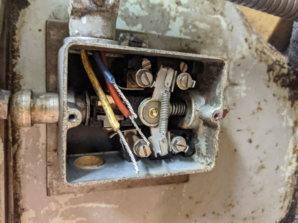
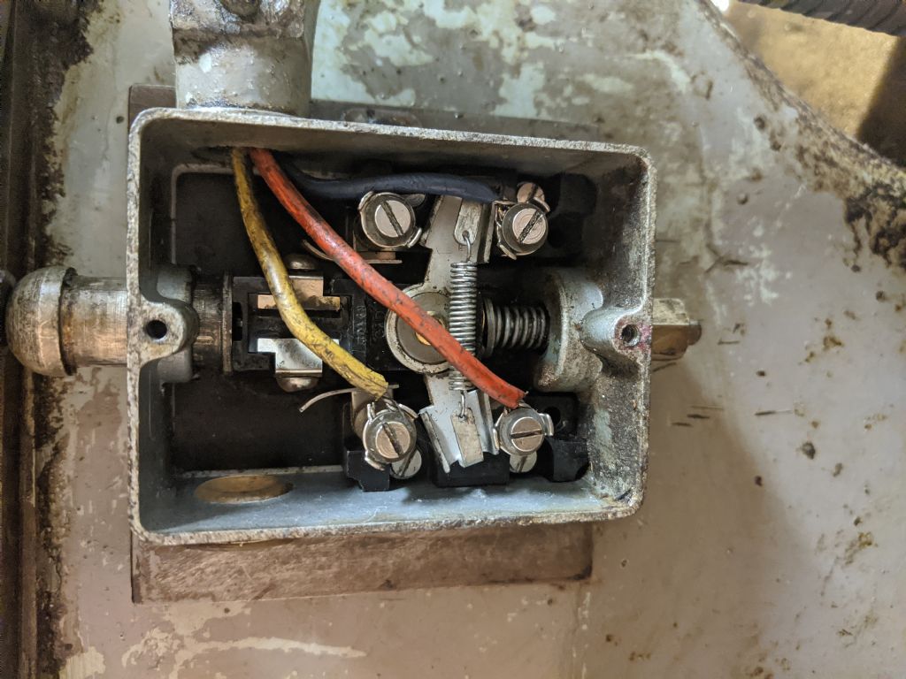
                Once that was done, I took advantage of the motor plate being out as I cleaned loads of gunk out from the frame. Then I looked at the limit switches wiring. I had Issues as the wire wasn't long enough to reach, but I found some slack, twisted the wires and got it all sorted.

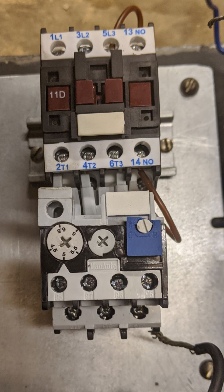
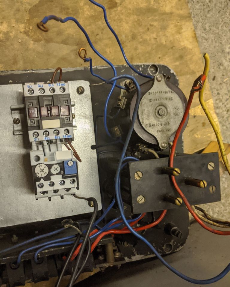
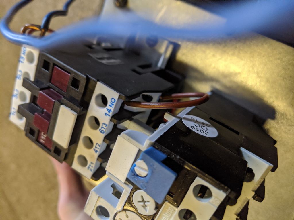
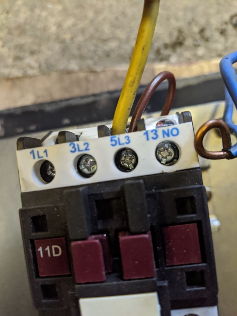
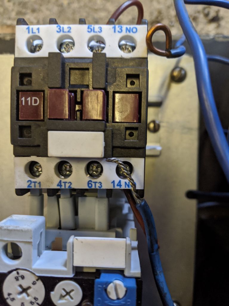
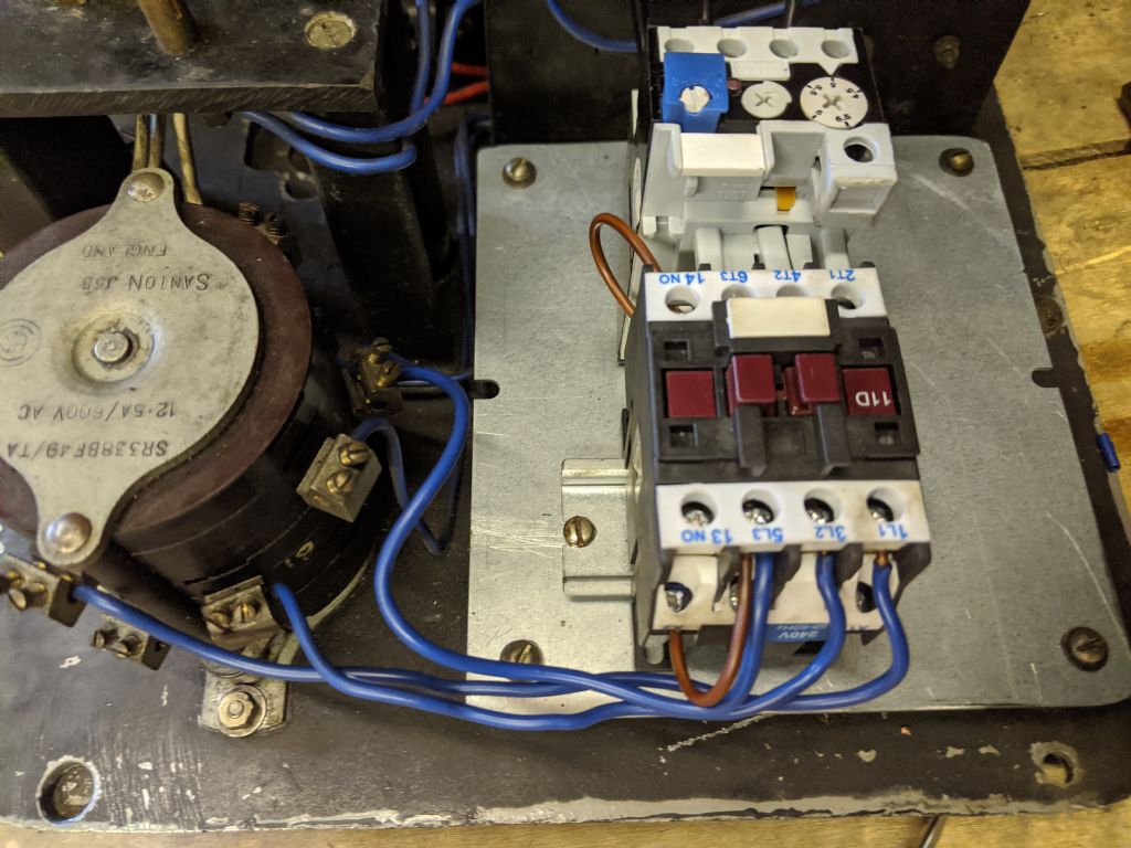
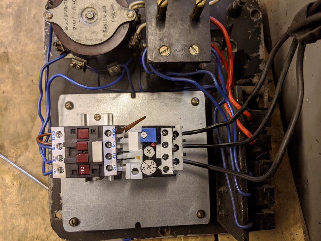
                So, the next task is to redo the gaskets and sort out the contactor. I need a little help figuring out the contactor since I'm not sure where the wires need to go

                img_20200323_161821.jpg

                img_20200323_170730.jpg

                img_20200323_174410.jpg

                img_20200323_174337.jpg

                img_20200323_191711.jpg

                img_20200323_192858.jpg


                So, from Phils lathes wiring, I understand I need the three blue cables coming from the switch to go into the L1 L2 and L3 at the top of the contactor.

                The yellow needs to go into the top of the contactor, then the red and blue somewhere else? Which ones do they need to go in?

                Also, which ones do the cables to the motor go in. Do they go into the lowest 3 at the bottom, or the other 4 on the relay?

                Looks like we're on lockdown now, So I may as well get it all done!

                Thanks

                img_20200323_193929.jpg

                img_20200323_193922.jpg

                Edited By Richard Kirkman 1 on 23/03/2020 21:18:53

                #459315
                Phil Whitley
                Participant
                  @philwhitley94135

                  Hi Richard, very neat work in the motor plate, I have done this job many times, and how easy it is is in direct proportion to how heavy the motor is, and how well you can get in to the job! It is NEVER easy!

                  The three blue wires from the rotary switch go to L1 L2 and L3 on the top of the contactor. 13 NO (normally open) and 14 NO are the holding in contacts which operate the no volt release. the three wires to the motor connect to the A b and C connections on the overload. Did you get a wiring diagram with the contactor? if so, can you scan it and email or post up a copy and I can do a diagram for you.

                  Phil.

                  #459318
                  Richard Kirkman 1
                  Participant
                    @richardkirkman1

                    Thanks, Phil, It really would have been a nightmare if I hadn't taken the motor plate out of the lathe! The jigsaw made it so much quicker, I would have been there a lot longer chain drilling and filing otherwise

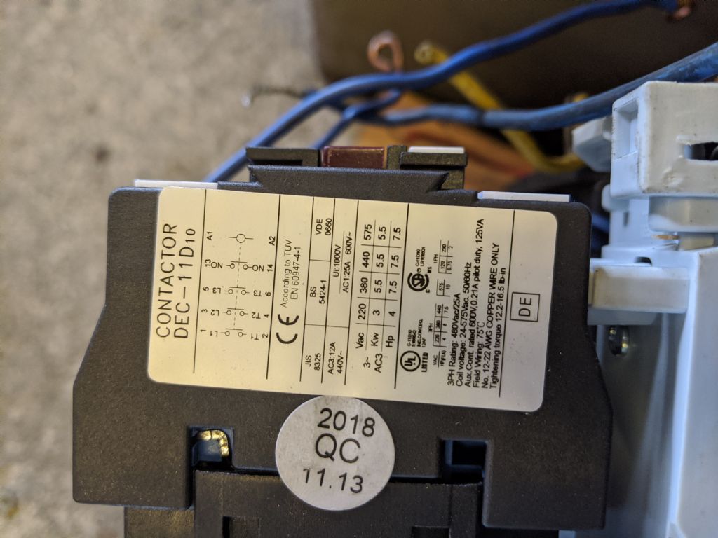
                    I'll fit the blue and black wires then I'll get some more pictures for you. It didn't come with a diagram but there was a diagram on the side of the contactor so I'll get a picture of that for you

                    Then I'll start draining the lathe so I can work on the gaskets. I'll take lots of pictures so you'll know exactly what to do when you replace your bearings! (Not that it's particularly difficult)

                    Thanks

                    #459322
                    Phil Whitley
                    Participant
                      @philwhitley94135

                      Have you linked the blue wire to the terminal above in the limit switch! See the diagram I did for you.

                      Phil

                      #459326
                      Richard Kirkman 1
                      Participant
                        @richardkirkman1

                        The blue yellow and red are all connected to the limit switch in the same locations as your lathe from the pictures you sent at the bottom of page 2 on this thread

                        #459332
                        Phil Whitley
                        Participant
                          @philwhitley94135

                          Yes, that is correct, but you also need a link wire from the blue wire terminal to the spare terminal on the switch, which is not visible in the pic. I have checked the wiring diagram, and it does show it. but it is not obvious on the pics. Look on the diagram in your manual.

                          Phil

                          Edited By Phil Whitley on 24/03/2020 14:44:39

                          #459333
                          Richard Kirkman 1
                          Participant
                            @richardkirkman1

                            I still need to connect all the blue yellow and red wires into the contactor? I'm not sure where they need to go, but looking at your diagram made a bit more sense

                            Or are you saying I need to connect the blue for the holding in switch elsewhere?

                            I'll get the pictures soon, just finishing some coursework

                            #459342
                            Richard Kirkman 1
                            Participant
                              @richardkirkman1

                              Picture on the side of the contactorimg_20200324_152600.jpg

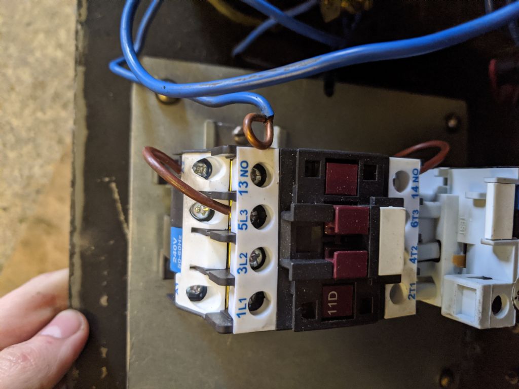
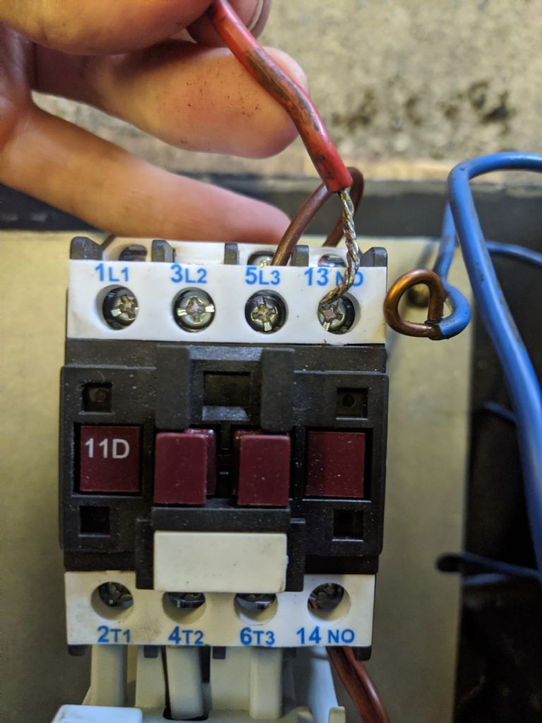
                              Then my electrician friend put two brown wires into the contactor, I don't really know why, but I'm sure there was a reason for it

                              img_20200324_152623.jpg

                              img_20200324_152634.jpg

                              Now, As far as i understand, then from the diagram you drew for me, the yellow needs to go into L3, the blue into the holding in thing at the bottom, then the red into the top one?

                              img_20200324_152658.jpg

                              img_20200324_152712.jpg

                              img_20200324_152721.jpg

                              #459345
                              Phil Whitley
                              Participant
                                @philwhitley94135

                                Hate to be the bearer of bad news, but the contactor appears (from the blue label) to have a 240v coil in it, you need to change this for a 400-415v coilfrown I also need a few good pics of the overload connections, but it will wait till you finish ter Uni stuff!

                                Phil

                                #459349
                                Emgee
                                Participant
                                  @emgee

                                  Could just run a neutral with the power supply and use 240v control.

                                  Emgee

                                  #459352
                                  Richard Kirkman 1
                                  Participant
                                    @richardkirkman1

                                    This is the contactor that I bought

                                    **LINK**

                                    Yes, it does seem to be 240v, but it says somewhere about 440v being used? Can it be made to work or am I better off ordering a 440v one like this

                                    **LINK**

                                    As if so, I need to order it quickly since who knows how long the royal mail is going to keep going

                                    Sorry about the faff, It shouldn't be too much of a problem. I might still be able to take it back

                                    Just as I'd got the wires in too. Just my lucklaugh

                                    img_20200324_163151.jpg

                                    img_20200324_163200.jpg

                                    #459353
                                    Phil Whitley
                                    Participant
                                      @philwhitley94135

                                      You could use a neutral, but better to get a 440v coil!

                                      Phil, I am back in about an hour!

                                      #459357
                                      Johnboy25
                                      Participant
                                        @johnboy25

                                        Is your lathe single phase or 3 phase? Could you send a photo of the motor info plate?
                                        John

                                        #459359
                                        Johnboy25
                                        Participant
                                          @johnboy25

                                          Sorry – didn’t see your latest post before hitting ‘send’ button. It’s 3 phase and if you’re in the uk or Europe, it will be 400V.

                                          As Phil said – you could use 230v if you’re got a Neutral on hand in the control box or where it’s fed from but that will need a bit of modification to the wiring.
                                          Again as Phil implied it would be easier to get a 400/440V coil or change the contactor out for a 400V version.

                                          John

                                          P.S. Don’t use it as it is – you’ll burn the coil out. 😳

                                          P.P.S. Chana are Telemecanique knock off’s.

                                          Edited By Johnboy25 on 24/03/2020 17:47:00

                                          Edited By Johnboy25 on 24/03/2020 17:52:01

                                          #459362
                                          Richard Kirkman 1
                                          Participant
                                            @richardkirkman1

                                            Thanks, Phil and John

                                            Just ordered a 400V one, the one I linked earlier, should be here on Thursday. I'll take the old one out then. Will the wiring be the same as it currently is?

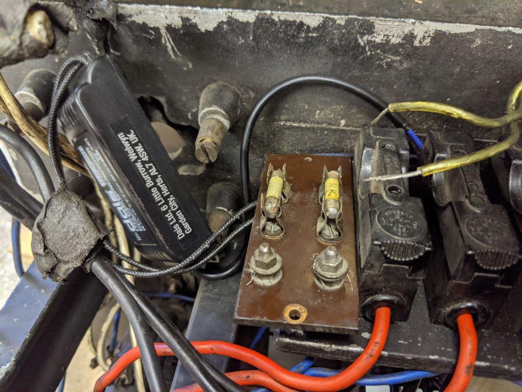
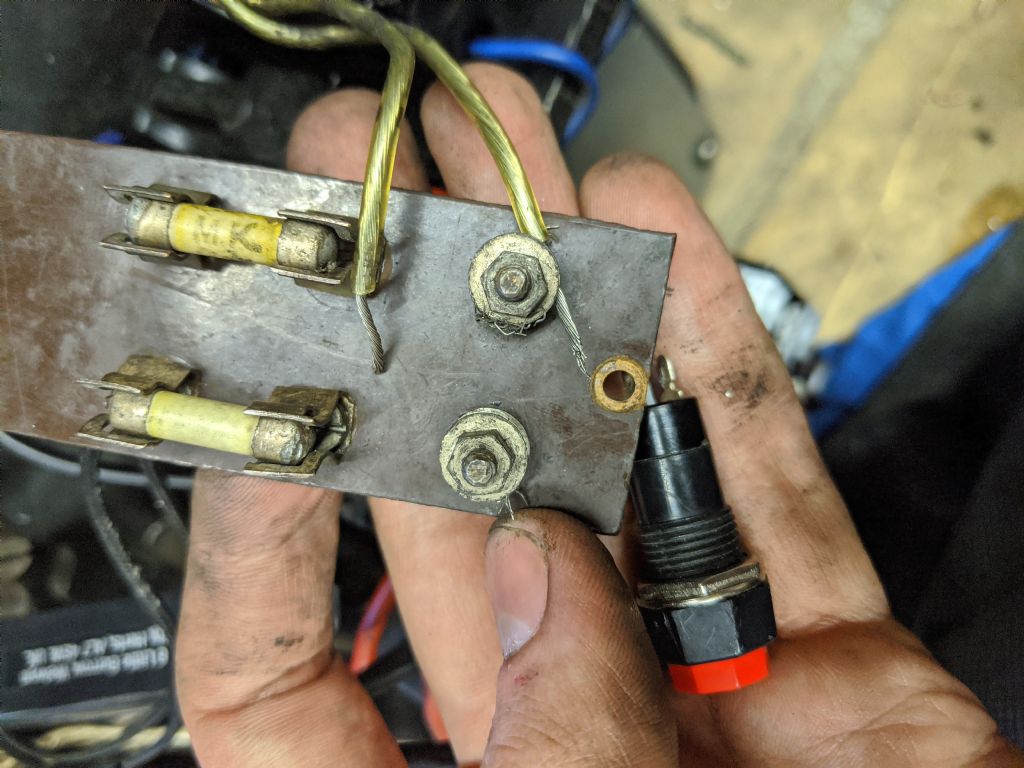
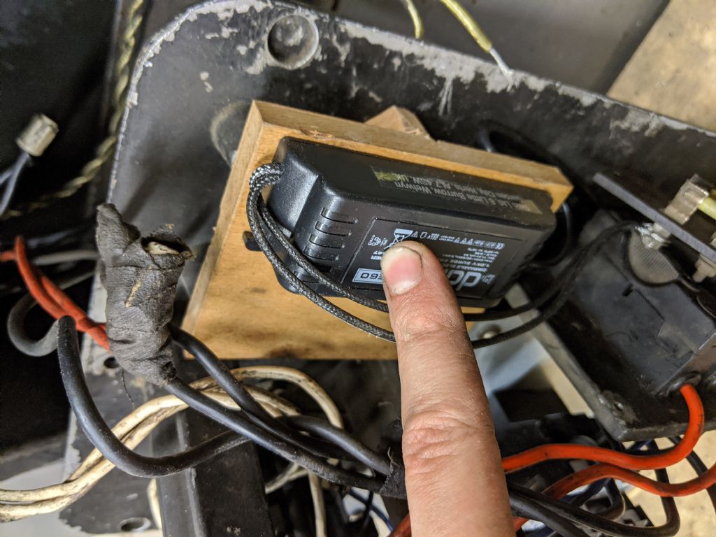
                                            Meanwhile, I've been looking at wiring for the lighting transformer, which seems to be pretty straightforward, but I'll post some pictures in case there's something I can't see is wrong.

                                            img_20200324_174210.jpg

                                            img_20200324_174235.jpg

                                            #459387
                                            Phil Whitley
                                            Participant
                                              @philwhitley94135

                                              Hi Again Richard,

                                              You have ordered a new contactor, good! you can use the existing overload portion, as you probably know, just remove it from the old contactor, and fit to the new one. On the overload, there should be a pair of normally closed connections which is the switch that breaks the holding in circuit if the current becomes to high, probably marked NC with a switch symbol between them. It is pointless to assume that the new contactor will be the same wiring as the old one, so post up a pic when it arrives, and we will do the wiring diagram then.

                                              Good progress, we will get there.

                                              Stay healthy

                                              Phil

                                              #459393
                                              Phil Whitley
                                              Participant
                                                @philwhitley94135

                                                AAAAAAARGH!!! have you connected the lighting unit to the two slidelock fuses? They will be 415 v or thereabouts! it will evaporate as soon as you put power to it! I assume that the lighting transformer is a 240v led power supply. Remeber that each line of the 3 phase supply is 240v, but between any two lines , due to them being 120 degrees out of phase, there is 415 or thereabouts. You would need (once again) to put a neutral into the machine which means using a 5 pin plug and socket instead of four, and 5 core cable as well. I would mount the transformer externally, plugged into a 13A socket, feed the low voltage into the machine, and use the switch you have fitted to the control panel to switch the output from the transformer to the light fitting.. The transformer originally fitted to these machines had a 415v primary, and 12 and 24v outputs, and some I think were 48V as well.

                                                Lets not have any big bangs eh!

                                                Phil.

                                                #459400
                                                Richard Kirkman 1
                                                Participant
                                                  @richardkirkman1

                                                  Thanks, this is exactly why I'm showing it

                                                  I still don't want to put an extra plug on, I want it all to run from one cable. But I don't want to put in a neutral in either. Surely this worked once before, so the component must exist. So, where would I be able to get a 415v to 12v transformer?

                                                  **LINK** This maybe? A bit expensive

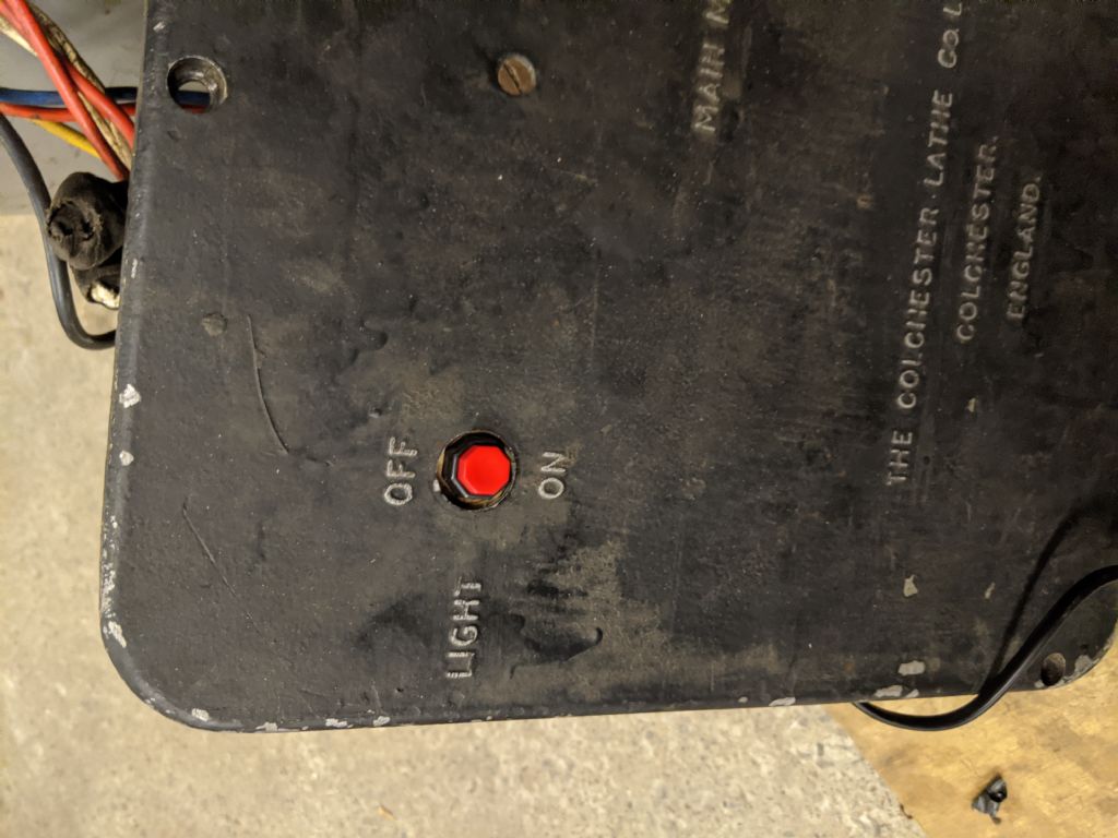
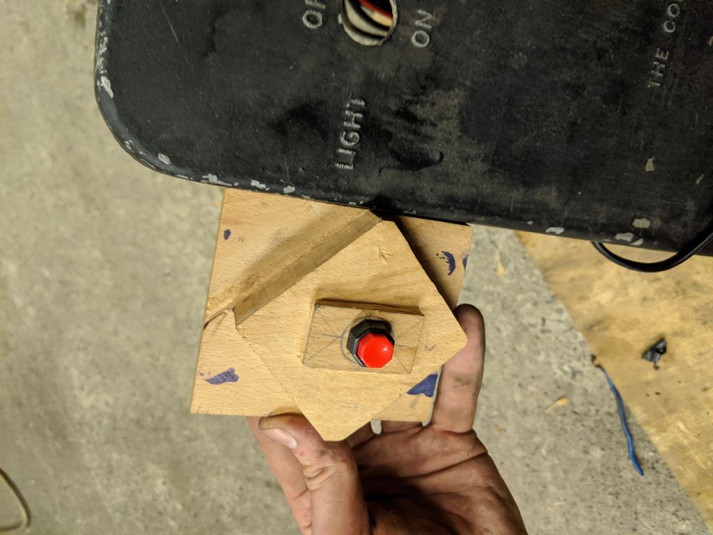
                                                  I've made a nice block for the switch to mount to, which is starting to look the part, a few more holes and it'll fit

                                                  Didn't get to start on the gaskets, but tomorrow is a new day!

                                                  Obviously the transformer won't be used anymore, but I took the pictures before I saw the message

                                                  img_20200324_193608.jpg

                                                  img_20200324_195524.jpg

                                                  img_20200324_195531.jpg

                                                  #459544
                                                  Phil Whitley
                                                  Participant
                                                    @philwhitley94135

                                                    Yes, that transformer would work, but it outputs 12v AC, and you would need DC for an LED, so you would need to convert, to DC, or use some other light source. I always look for the simplest solution! Will see if I can turn anything up.

                                                    Phil.

                                                    #459546
                                                    Phil Whitley
                                                    Participant
                                                      @philwhitley94135

                                                      Maybe this, link

                                                      And feed the output to your existing led transformer. Drop an email to RS just to check that it will suit your use, but it looks good to me. Masses of transformers used on ebay!

                                                      Phil

                                                    Viewing 25 posts - 151 through 175 (of 797 total)
                                                    • Please log in to reply to this topic. Registering is free and easy using the links on the menu at the top of this page.

                                                    Advert

                                                    Latest Replies

                                                    Viewing 25 topics - 1 through 25 (of 25 total)
                                                    Viewing 25 topics - 1 through 25 (of 25 total)

                                                    View full reply list.

                                                    Advert

                                                    Newsletter Sign-up