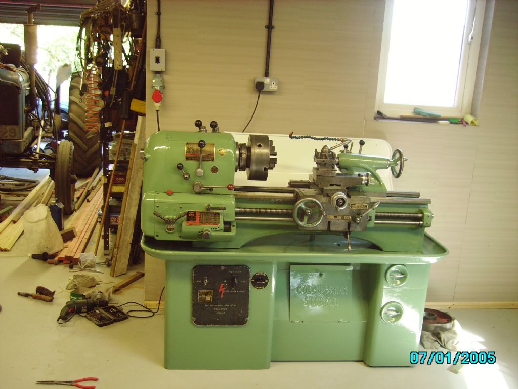
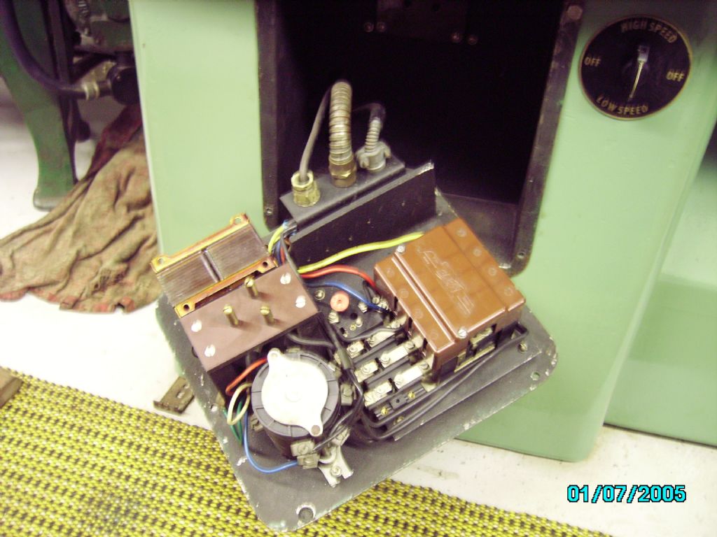
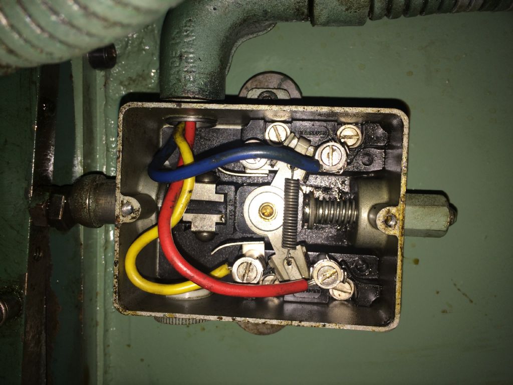
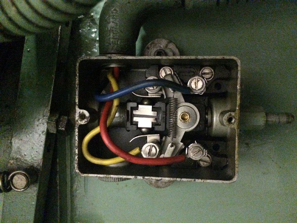
Colchester Student Mk1 Won’t Start
Colchester Student Mk1 Won’t Start
- This topic has 796 replies, 39 voices, and was last updated 5 June 2021 at 16:31 by
 Phil Whitley.


- Please log in to reply to this topic. Registering is free and easy using the links on the menu at the top of this page.
Latest Replies
-
- Topic
- Voices
- Last Post
-
-
Help recommend a milling machine?
Started by:
richard1989
in: Beginners questions
- 12
-
2 August 2025 at 22:50
HOWARDT
-
Depth of cut cowells me90
Started by:
kinross1
in: Manual machine tools
- 3
-
2 August 2025 at 22:48
Fulmen
-
CNC Coolant
1
2
Started by:
Steve355
in: CNC machines, Home builds, Conversions, ELS, automation, software, etc tools
- 13
-
2 August 2025 at 22:41
HOWARDT
-
Cut knurling
Started by:
Fulmen
in: Workshop Tools and Tooling
- 12
-
2 August 2025 at 21:46
Fulmen
-
Seig SX3.5ZP
Started by:
IanT
in: Manual machine tools
- 7
-
2 August 2025 at 21:27
IanT
-
Cutting thin slots in 12mm mild steel
Started by:
Peter Simpson 3
in: Beginners questions
- 9
-
2 August 2025 at 20:26
JasonB
-
100mm 4 jaw chuck servicing
Started by:
John Millis
in: Workshop Tools and Tooling
- 5
-
2 August 2025 at 20:09
John Millis
-
Traditional fly press uses
Started by:
choochoo_baloo
in: Workshop Tools and Tooling
- 20
-
2 August 2025 at 18:55
old mart
-
Boiler hydraulic test 4 hours
Started by:
endckr111
in: Stationary engines
- 10
-
2 August 2025 at 18:33
DC31k
-
Bridgeport ways and wear
Started by:
inline
in: Manual machine tools
- 11
-
2 August 2025 at 18:29
inline
-
My experiences with an ELS lathe
Started by:
David Senior
in: CNC machines, Home builds, Conversions, ELS, automation, software, etc tools
- 10
-
2 August 2025 at 18:24
Geoff Rogers
-
Arc Euro Trade Ltd.
1
2
3
Started by:
Ketan Swali
in: General Questions
- 49
-
2 August 2025 at 18:22
James Hall 3
-
Model Turbines
1
2
…
24
25
Started by:
Turbine Guy
in: Stationary engines
- 28
-
2 August 2025 at 17:39
Turbine Guy
-
Hemingway taper turning attachment
Started by:
garyash
in: Workshop Tools and Tooling
- 1
-
2 August 2025 at 12:01
garyash
-
Record 74 auto vice
1
2
Started by:
Danni Burns
in: Workshop Tools and Tooling
- 11
-
2 August 2025 at 10:48
Danni Burns
-
Depreciation of Intel processors
Started by:
Michael Gilligan
in: Electronics in the Workshop
- 6
-
2 August 2025 at 10:45
Michael Gilligan
-
Help Wire 3 Phase 2 Speed Motor
1
2
Started by:
Allan Day
in: Electronics in the Workshop
- 15
-
2 August 2025 at 10:20
Mark Hall
-
Boiler Design – issue 4765
1
2
…
9
10
Started by:
Charles Lamont
in: Model Engineer & Workshop
- 29
-
2 August 2025 at 09:23
Michael Gilligan
-
What Did You Do Today 2025
1
2
…
8
9
Started by:
JasonB
in: The Tea Room
- 33
-
1 August 2025 at 20:46
Durhambuilder
-
retirement aaargh!
Started by:
grimme
in: General Questions
- 18
-
1 August 2025 at 19:48
martin haysom
-
Why am I confused?
Started by:
JimmieS
in: The Tea Room
- 5
-
1 August 2025 at 19:31
martin haysom
-
What a flipping cheek !
Started by:
Speedy Builder5
in: The Tea Room
- 6
-
1 August 2025 at 18:59
Gary Wooding
-
Suspicious Post? (Letters)
Started by:
Nigel Graham 2
in: The Tea Room
- 5
-
1 August 2025 at 18:46
SillyOldDuffer
-
Transwave converter – plugged in motor, tripped RCD
Started by:
ell81
in: Beginners questions
- 10
-
1 August 2025 at 18:42
Robert Atkinson 2
-
Model Engineer Magazine Collection
Started by:
mfengine1
in: Books
- 9
-
1 August 2025 at 18:05
mfengine1
-
Help recommend a milling machine?


