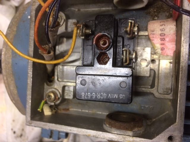
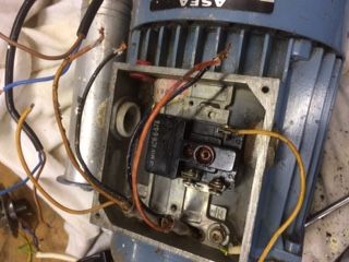
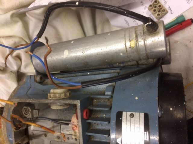
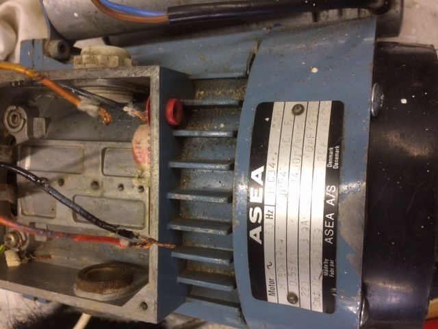
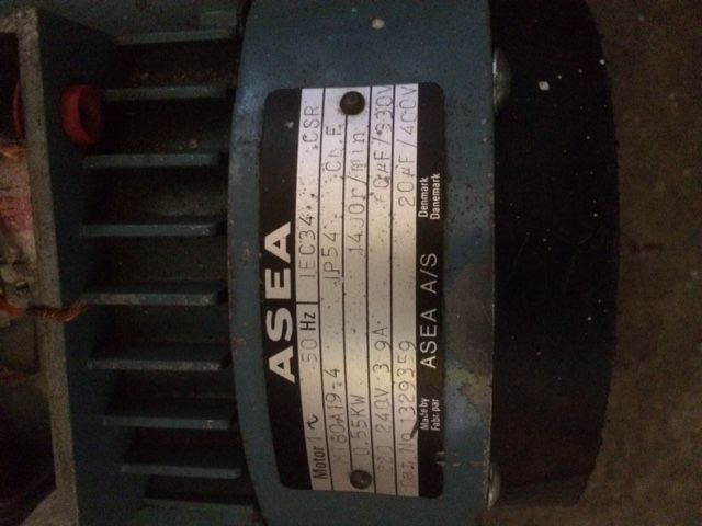
I guess you're not getting many answers Dennis because your motor is a shade mysterious, requiring more than average detective work to suss out what the various connections are. To be certain someone would have to recognise the motor and know how it was connected. Might not be luck – it's about 50 years old, was made by a defunct company, and may not have been common in the UK.
Back to the clues: we know it's single-phase, has two capacitors, and an external switch (rather than a centrifugal switch). You also said :
The 3 wire group. Lets say the wire colours are Black, Orange & Yellow.
Yellow to Black = 8ohms,
Yellow to Orange = 15 ohms
Orange to Black = 15 ohms.
That's a bit of a worry because I don't understand how those three measurements add up. With 3 connections, I'd expect one of the 'Orange' measurements to be 8 + 15 = 23 ohms. Could you have made a mistake?
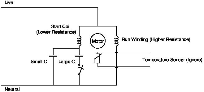
Assuming you did, this is the circuit I'd try. WARNING! I am not a motor expert, but I do understand how to wire up and test a motor like this safely. While I hope I've made an intelligent guess, I am guessing. Also, in my own workshop I'd be happy to risk damaging the motor. I might have start and run windings the wrong way round, and/or the large and small capacitors.
If you're brave, have a go. You might prefer to wait to see if this post wakes up an expert; there are people on the forum with far more experience of motors than I.

I suggest:
- The odd pair of wires are connected to a temperature sensor used to detect when the motor is overheated. They can be ignored.
- The start winding is the lower resistance winding. (Yellow Black – 8 ohms)
- The run winding is the higher resistance winding. (Yellow Orange – 15 ohms*)
- The start capacitor is the 60uF
- The run capacitor is the 20uF
* Note uncertainty – this could be wrong because you said Orange Black was also 15 ohms making the wiring ambiguous I'd be much happier if Orange-Black was 23 ohms.
Hope this helps!
Dave
SillyOldDuffer.


