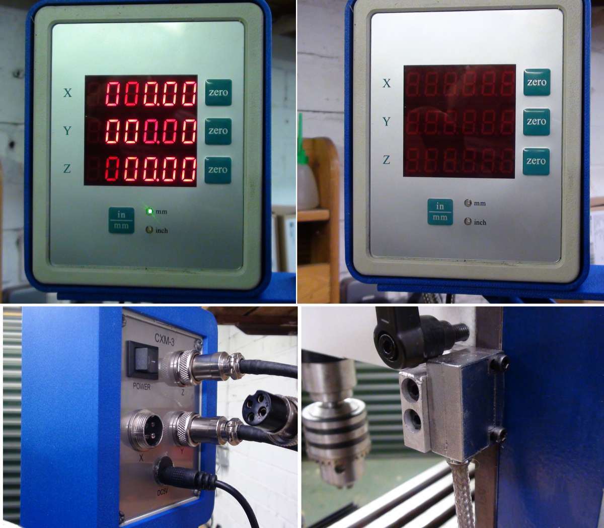
Alternatives for a DRO display change
Alternatives for a DRO display change
- This topic has 10 replies, 4 voices, and was last updated 31 August 2025 at 11:12 by
 John Hinkley.


- Please log in to reply to this topic. Registering is free and easy using the links on the menu at the top of this page.
Latest Replies
-
- Topic
- Voices
- Last Post
-
-
Emco Compact 5 Modifications
1
2
…
4
5
Started by:
Graham Meek
in: Manual machine tools
- 12
-
31 August 2025 at 16:23
Graham Meek
-
What Did You Do Today 2025
1
2
…
9
10
Started by:
JasonB
in: The Tea Room
- 37
-
31 August 2025 at 16:20
Dalboy
-
Sensitive tailstock for mini lathe
Started by:
dk0
in: Workshop Tools and Tooling
- 10
-
31 August 2025 at 15:42
old mart
-
Folding Knife
Started by:
Vic
in: The Tea Room
- 4
-
31 August 2025 at 15:14
Clive Foster
-
End Mill Sharpening Jig
Started by:
Vic
in: Workshop Tools and Tooling
- 9
-
31 August 2025 at 14:34
Vic
-
Feed Water
Started by:
Richard Simpson
in: General Questions
- 13
-
31 August 2025 at 14:08
cogdobbler
-
Parting off on a mini lathe
Started by:
Andy Brocklehurst
in: Beginners questions
- 16
-
31 August 2025 at 13:47
JasonB
-
Alternatives for a DRO display change
Started by:
John Hinkley
in: General Questions
- 4
-
31 August 2025 at 11:12
John Hinkley
-
Dickson Tooling Offer
Started by:
JohnF
in: Hints And Tips for model engineers
- 12
-
31 August 2025 at 10:57
southernchap
-
Milling for beginners book, Where?
Started by:
andy198712
in: Beginners questions
- 9
-
31 August 2025 at 10:34
southernchap
-
NU tool milling machine
Started by:
joseph tatler
in: Manual machine tools
- 8
-
31 August 2025 at 10:15
southernchap
-
Myford VMB mill, head lift.
Started by:
lctikka61
in: Manual machine tools
- 4
-
31 August 2025 at 10:04
Michael Gilligan
-
My week this week! My workshop videos
1
2
…
11
12
Started by:
Phil Whitley
in: The Tea Room
- 16
-
30 August 2025 at 18:55
Phil Whitley
-
Mesh Communication
Started by:
Vic
in: The Tea Room
- 4
-
30 August 2025 at 18:17
Vic
-
Bendy Flexible Plywood
Started by:
Henry Buckeldee
in: Related Hobbies including Vehicle Restoration
- 16
-
30 August 2025 at 17:05
Henry Buckeldee
-
Bassett Lowke “Eclipse”
Started by:
JasonB
in: Stationary engines
- 6
-
30 August 2025 at 16:42
Jim Nic
-
DRO Zero position (a bit academic I know)
Started by:
Lee Reynolds 1
in: Electronics in the Workshop
- 4
-
30 August 2025 at 14:30
Lee Reynolds 1
-
125 mm chuck onto my lathe
Started by:
Steve Huckins
in: General Questions
- 13
-
30 August 2025 at 14:20
HOWARDT
-
Mercer comparator gauge repair help.
Started by:
Graeme Seed
in: Workshop Tools and Tooling
- 4
-
30 August 2025 at 13:43
Graeme Seed
-
Painting mating surfaces
Started by:
Martin Cooper
in: Beginners questions
- 11
-
30 August 2025 at 13:26
JasonB
-
Be Aware of Scammers
Started by:
Neil Wyatt
in: Website Announcements
- 1
-
30 August 2025 at 12:36
Neil Wyatt
-
Sourcing Dexion SpeedFrame beam section
Started by:
Greensands
in: General Questions
- 5
-
30 August 2025 at 09:36
Clive Foster
-
Hello.
Started by:
smokeyjoe25
in: Introduce Yourself – New members start here!
- 4
-
29 August 2025 at 22:13
Howard Lewis
-
Warco Super Major Milling Machine – Stripping Gearbox
Started by:
Lee Jones 6
in: Manual machine tools
- 10
-
29 August 2025 at 17:47
Colin Heseltine
-
interchangeable Myford beds
Started by:
Kundrus
in: Manual machine tools
- 4
-
29 August 2025 at 15:43
Kundrus
-
Emco Compact 5 Modifications
1
2
…
4
5


