3 Phase in a Model Engineers workshop

Advert

3 Phase in a Model Engineers workshop

Home Forums General Questions 3 Phase in a Model Engineers workshop

Viewing 25 posts - 26 through 50 (of 54 total)
  • Author
    Posts
  • #479684
    David Evans 16
    Participant
      @davidevans16

      Hi, new here but have a very similar problem.

      I have a rotary phase converter rated at 4.5kW. It runs the Colchester 1800 lathe no problem but will only run my Universal mill on the low speed range (two speed motor), if I try and run it on the high speed range it won't start at all unless I take the tension completely off the belts. The mill is 2.2kW but I think the mechanical drag is just too much for it on start up.

      David

      Advert
      #479685
      Phil Whitley
      Participant
        @philwhitley94135

        The contactor is in the hinged lid, or at least it appears to be, because it is an unfamiliar type. I am intrigued by the round isolator(?) above the contactor, and also by the long earthed pin that projects from the back of the box? ot appears to operate something on the round isolator. given that you have three fairly well balanced phases at aproximately the right voltage, it looks to me like the machine is drawing excessive current because it has stiffened up, or you are trying to start it "in gear"?

        Phil

        East Yorkshire https://www.youtube.com/user/philhermetic/videos

        Edited By Phil Whitley on 13/06/2020 21:24:13

        #479706
        Anthony Gardner
        Participant
          @anthonygardner18070

          Hi Phil,

          Thanks for the quick response. You are thinking along the same lines as me. When I hold the push button in and run the machine it does make a lot of noise that I don't remember it doing back in Oxford. The clutch is definitely not engaged and the machine has been idle for about 4 years. It is belt driven (4 belts) so I will try to release them. Not easy as I have to lift the motor plate and it is flippin heavy. The pully does rotate freely by hand. As for a contactor somewhere in the machine I cant think where it could be, but I will investigate. What I really need is a wiring diagram. The manual that I have does not give one. but I Do have contact details for a Cincinnati office in the UK so I will try to contact them. The long pin, by the way is a mechanical device that stops you opening the door if the isolator is in the on position.

          I really appreciate your help. Cheers.

          #479740
          Robert Atkinson 2
          Participant
            @robertatkinson2

            If the isolator is tripping as you say " The isolator for the mill is a Telemecanique and is the one I used in Oxford. As it is the trip on this isolator that keeps tripping " and is the blue/grey bok on the wall (left side) I suspec that it is mis-wired. Many have a 240V coil and require a connection between one phase and neutral.

            There are a few possibilities for mis-wiring. Common ones are:
            Connecting coil beween phases insead of phase to neutral.
            The phase the coil is connected to is not a true phase. This is less of a problem with the idler motor converter you have, but try connecting the contactor coil supply to a different phase. Note that the mis-wire could be in a number of locations.

            There is also a posibility that the mill has failed electrically in storage. Possible causes are damp and rodent or insect activity. Do you have a multimeter and a insulation tester ("megger&quot? If so check the phase to pase resistance of the motor windings and phase to ground for motor and wiring.
            Robert G8RPI.

            p.s. I looked at Transwave's information on converters and was surprised how biased it was.

            #479741
            Les Jones 1
            Participant
              @lesjones1

              Hi David,
              I think you should start your own thread relating to your problem. It can get very confusing discussing a number of different problems in the same thread.

              Hi Tony,
              I think an extra picture of the isolator door with the camera moved to the left a bit or the door swung about 30 degrees more closed might help. In the original picture I can't decide if the terminals on what I think is the contactor are in the horizontal or vertical plane. ( I think from the fact that it looks like the contactor coil is at the bottom of the picture that the contacts are in the horizontal plane.) It might also help identify the two things either side of what I think is the contactor. ( My best guess on these is thermal overload cut outs, one for the main motor and one for the coolant pump.) I think the right hand set of the four contacts on the contactor is the maintainer set to hold the coil in when the start button is released. I will avoid making any more comments at the moment as Phil seems to be thinking along the right lines and recommending sensible actions to diagnose the problem.

              Les.

              Edited By Les Jones 1 on 14/06/2020 09:21:39

              #479743
              DC31k
              Participant
                @dc31k
                Posted by Anthony Gardner on 14/06/2020 00:02:56:

                …What I really need is a wiring diagram

                It may be worth a look through the stuff here if you did not already know of it:

                http://vintagemachinery.org/mfgindex/detail.aspx?id=2097&tab=3

                Edited By DC31k on 14/06/2020 09:27:37

                #479744
                Anonymous

                  Are the measured phase to phase voltages off load? If so what do they measure on load, on both the lathe and mill.

                  Andrew

                  #480084
                  Anthony Gardner
                  Participant
                    @anthonygardner18070

                    Hi All,

                    OK. So now I have, with some difficulty, managed to remove the belts. Not sure how the devil I am going to get them back on as when I removed the last belt the motor plate dropped to the bottom of the machine and it must weigh the best part of 2 cwt. That's a problem for later. With the belts removed I pressed the on button and the same problem. Runs for a few seconds, then stops. So it is deffinately not the machine causing the problem for which I am thankful.

                    The thing that puzzles me is that is running the motor from a rotary converter any different from running the motor from a 3 phase mains supply.

                    Looking at the inside of the hinged door, the component below the rotary switch, I am guessing is the contactor. Could this be where the problem lies.

                    Cheers, Tony

                    #480088
                    Steviegtr
                    Participant
                      @steviegtr

                      Is it a rotary converter or a tranverter. A rotary is a 3phase motor generater The unit you have looks like the ones with your original single phase as lets say L1 & a bank of capacitors to lead the sine wave which we will call L2, then an inductor to make the supply lag. L3. Creating artificial 3 phase. I know of 2 people who have these & watching them start there machines is weird. 1 has to hold a switch on the front panel in a certain position to get the lathe running , it buzzes like hell. Then he moves the switch to a different position to run. The artificial ones give slightly different reading on each phase. If your contactor coil is 240v then I suggest you try using a different phase. Move them twice in effect. Once reverses the motor twice back forward. I did not want to get into this. If I was there I could sort it for you. I am sure. You may kick yourself once it gets done.

                      Steve.

                      #480156
                      Phil Whitley
                      Participant
                        @philwhitley94135

                        OK well that has ruled out a lot of possibles. So the motor runs, does it run smoothly and quietly, or does it run slowly and "growl" ? do you still have to hold your finger on the start button to keep the motor running, or does the contactor hold in and then trip? Is the tripping still at the wall mounted breaker? what is the HP of the mill motor and the lathe motor?

                        Phil

                        #480170
                        Phil Whitley
                        Participant
                          @philwhitley94135

                          Looking at the picture of the contactor, it looks like there is two sets of overloads, the one on the left with the black wires, I am guessing is the main motor, the one on the right, with the red wires I am guessing is the coolant pump. Try running the coolant pump, and the table feed motor if it has one. Do you have a multimeter?

                          Phil

                          #480190
                          Anonymous
                            Posted by Phil Whitley on 16/06/2020 09:38:41:

                            what is the HP of the mill motor and the lathe motor?

                            RTFP!

                            #480206
                            Anthony Gardner
                            Participant
                              @anthonygardner18070

                              The lathe has a 3HP 3 phase motor and the mill has a 5HP 3 phase motor.

                              The lathe runs fine. That has a 4 wire feed, 3 phases and a neutral.

                              The mill motor will only run if I keep my finger on the button and it does not run smoothly at all. It sounds as though it is struggling and sounds terrible. It runs for a few seconds then stops. I then press the on button again and it does the same thing. After a few attempts at this the trip on the main isolator on the wall trips out.

                              The phase converter is a Transwave Rotary Converter and runs the lathe with no problem.

                              #480214
                              Emgee
                              Participant
                                @emgee

                                Anthony

                                Sounds to me that you need someone who knows what they are doing to be hands on with the machine, may cost a bit but at least you will be best advised.

                                Emgee

                                #480344
                                Phil Whitley
                                Participant
                                  @philwhitley94135

                                  OK, it sounds like the motor is either off a phase, or maybe has got damp and has leaky insulation, have you tried the coolant pump/table feed to see if they run correctly? What are the earthing arrangments for the installation? If you have a multi meter you need to turn off the power, isolate the machine and start testing through each phase from the isolator on the machine, through the contactor with the contactor held in manually, through the overload, and to the motor. You could also do with a megger to do an insulation test on the motor. I think Emgee is right, we are coming to the point where you need someone on site with basic test gear to sort this out. If it was running at your previous premises, it can't be much wrong with it. there is a possibility that there is a phase off at the motor caused by a bad contact either in the contactor, , or in the overload. If the coolant/table feed works, and the main motor doesnt we have confirmed three good phases at the machine, if they don't work correctly we can suspect the supply to the machine. Incidentally, what type of lathe is it, and why does it need a neutral? Where are you in the country?

                                  Phil

                                  Edited By Phil Whitley on 16/06/2020 21:03:15

                                  #480345
                                  Phil Whitley
                                  Participant
                                    @philwhitley94135

                                    Right, I have just "RTFP" again and I see it is a Colchester 1800, do you know why it needs a neutral? I also see you are in the New forest! Bit too far from me in East Yorkshire, any industrial sparkies in that area read this forum?

                                    Phil

                                    Edited By Phil Whitley on 16/06/2020 21:19:32

                                    Edited By Phil Whitley on 16/06/2020 21:20:18

                                    #480359
                                    Steviegtr
                                    Participant
                                      @steviegtr
                                      Posted by Phil Whitley on 16/06/2020 21:16:35:

                                      Right, I have just "RTFP" again and I see it is a Colchester 1800, do you know why it needs a neutral? I also see you are in the New forest! Bit too far from me in East Yorkshire, any industrial sparkies in that area read this forum?

                                      Phil

                                      Edited By Phil Whitley on 16/06/2020 21:19:32

                                      Edied By Phil Whitley on 16/06/202

                                      Edited By Steviegtr on 16/06/2020 22:11:24

                                      #480420
                                      Les Jones 1
                                      Participant
                                        @lesjones1

                                        One important question asked by Andrew Johnston on 14/6/20 at 09:31 has not yet been answered, I was thinking of doing a simple test using 6 old fashioned mains filament lamps of 60 to 100 watts rating. (All the same rating) The idea is to have three series connected pairs of lamps with each pair connected across the three phases on the motor. (Making the connection at the output side of the thermal trip that feeds the spindle motor is probably the easiest.) The brightness of the lamps would give a reasonable idea of phase balance.(50 watt GU10 bulbs could also be used as they are easier to obtain. ) Another test that could be done is to disconnect the spindle motor at the output of the thermal trip and see if the contactor stays in and the coolant pump motor runs. I am inclined to agree that someone is required on site who is used to working on three phase motors and tracing exactly how the contactor maintainer contact and interlocks are wired.

                                        Les.

                                        #480447
                                        Phil Whitley
                                        Participant
                                          @philwhitley94135

                                          You are right Les, but it would be a bit of a faff to set it up, I am working on the assumption that if it starts a 3hp motor, it should start a 5hp off load with the belts off, and it isn't. it is rated at 7.5 hp, and should be able to deliver about 15a peak, the 5hp should be demanding about 8-10a, so it shouldnt be a problem, especially so with the belts off. Of course we do need to test that the three phases that are running the lathe are also reaching the mill!

                                          Original poster, can we have a pic of the inside of the rotary convertor pls?

                                          Phil

                                          #480492
                                          Les Jones 1
                                          Participant
                                            @lesjones1

                                            Hi Phil,
                                            At first I had doubts about it being a ROTARY converter as I could net see the motor part of the converter. At sight it looked like the converter box was right against the wall. On the Transwave website the motors all seem to be mounted on the back of the box. I had a closer look at the picture and I think I can just see the fan end of the motor behind the output socket. I can't understand how the contactor can pull in when fed via the start button but not by the maintainer contact. The only thing I can think of that may be happening is the contactor is chattering in and out while the start button is pressed. When it pulls in and the load is put on the phase that is supplying the coil the coil then drops out. As soon as this happens the load on the phase that is supplying the coil is removed so it pulls in again. If this is happening then it would not hold in when the start button is released. Monitoring the coil voltage (Or listening for noise from the contactor.) would prove or disprove the theory. (I am assuming that there is no fault in the internal machine wiring as we where told is was working in the previous location.)

                                            Les.

                                            #480583
                                            Stuart Smith 5
                                            Participant
                                              @stuartsmith5

                                              It may be that the motor starting current is higher than the converter or the single phase mains supply can supply without too high a voltage drop.

                                              Bearing in mind that the starting current will be about 6 times the full load running current, so the 3 phase starting current could be in the region of 50 amps.

                                              The attached document shows the size of motors that can be connected to the DNO network. The largest 3 phase motor that can be connected without any checks is 6 HP and the largest single phase is only 1 HP. This is to avoid voltage fluctuations affecting other nearby customers.

                                              **LINK**

                                              This is something that never seems to be mentioned when discussing the use of single phase to 3 phase converters.

                                              Stuart

                                              #480594
                                              Anthony Gardner
                                              Participant
                                                @anthonygardner18070

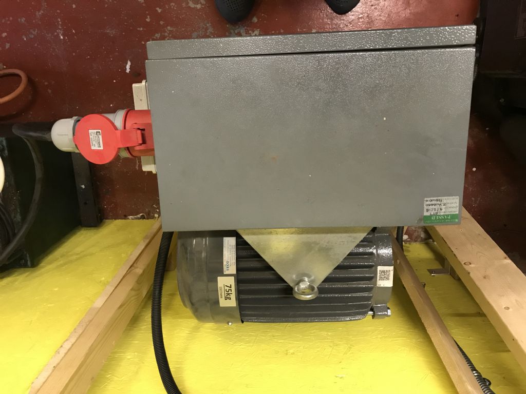
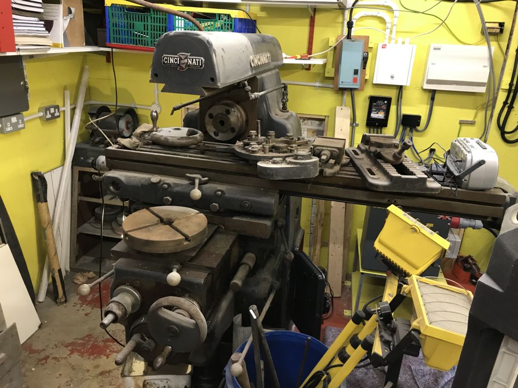
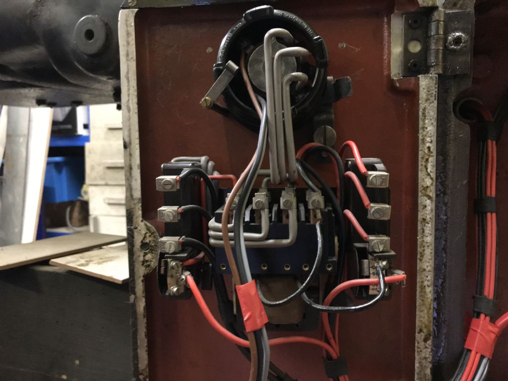
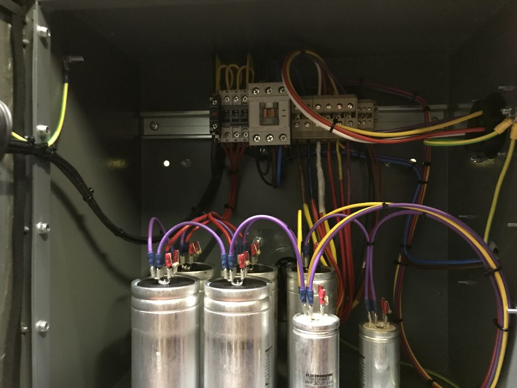
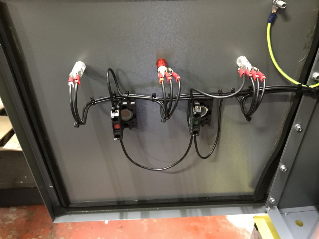
                                                img_2538.jpgimg_2537.jpgimg_2535.jpgimg_2534.jpgOK. So now I am getting worried.

                                                Here are some more photos.

                                                1. Plan view of the phase converter.

                                                2. Inside of the door of the phase converter.

                                                3. inside of the phase converter.

                                                4. Inside of the hinged door showing the rotary switch and what I believe to be the contactor on the mill.

                                                5. General view of the mill.

                                                img_2528.jpg

                                                #480600
                                                Phil Whitley
                                                Participant
                                                  @philwhitley94135

                                                  You are right again Les, I can also see the fan cowl now you have pointed it out! I am going on the assumption that the maintaining circuit is not workin because the overloads have either already opened due to excess current, or one of the overloads is open circuit, or stuck in the overload position and is causing the motor to try to start on two phases. This would have the effect (depending on how it is connected), of preventing the contactor maintaining circuit working, but would energise the coil when the start button was pressed. The contactor type, with two seperate overloads, which is what appears to be in the hinged lid, is unfamiliar to me. It appers that in order to start the machine, the start button brought in the contactor, and started the main motor, and you could then select coolant with the rotary switch, and either motor overloading or faulting would stop the whole machine. Unusual, but saves using two contactors. The only Cincinnati of this type I have ever encountered was in the seventies in a local workshop owned by a mate of mine, and as I recall now I think the table feed is mechanical and run from the main gearbox, rather than by a seperate motor. Unfortunately it never broke down electrically, so I never got to tear into it!


                                                  Stuart, the transwave should be able to deal with the starting current without a problem, especially with the belts off, it is after all, rated for starting a 7.5 hp motor. Your point about the single phase supply to the transwave is another possibility to consider though, we always assume MCB's are installed, but this may not be the case. It seems that the tripping is not taking place on the single phase side, so once again, we need someone on site with an AVO and a Megger!

                                                  Phil

                                                  Edited By Phil Whitley on 17/06/2020 21:35:10

                                                  #480601
                                                  Phil Whitley
                                                  Participant
                                                    @philwhitley94135

                                                    No need to worry Anthony, the inside of the convertor looks fine!, and that is a much better pic of the main contactor, I am going to have a close look at the wiring on that !

                                                    Phil

                                                    #480651
                                                    Anthony Gardner
                                                    Participant
                                                      @anthonygardner18070

                                                      Thanks to all of you for trying to help. I really appreciate it.

                                                      I have put a request out on the "Nextdoor" web site to the Ringwood area to see if there is an electrician with experience in this in the area.

                                                      Cheers.

                                                    Viewing 25 posts - 26 through 50 (of 54 total)
                                                    • Please log in to reply to this topic. Registering is free and easy using the links on the menu at the top of this page.

                                                    Advert

                                                    Latest Replies

                                                    Home Forums General Questions Topics

                                                    Viewing 25 topics - 1 through 25 (of 25 total)
                                                    Viewing 25 topics - 1 through 25 (of 25 total)

                                                    View full reply list.

                                                    Advert

                                                    Newsletter Sign-up