2″ Minnie Boiler

Advert

2″ Minnie Boiler

Home Forums Beginners questions 2″ Minnie Boiler

Viewing 16 posts - 1 through 16 (of 16 total)
  • Author
    Posts
  • #7299
    Packmule
    Participant
      @packmule
      Advert
      #163339
      Packmule
      Participant
        @packmule

        Hi all,

        Info needed re the front Boiler tube plate and firebox plate.

        Because it is a change from the original drawing I need to supply drawing of the change, are the drawings adequate ? if not what changes are req'd ?

        They are shown full size in:

        album 2" Minnie

        #163350
        JasonB
        Moderator
          @jasonb

          I would have said you need to supply some dimensions to show spacing of tubes & stays, thickness of plates, size of flanges and all backed up by calculations.

          That looks a very large unsupported flat area between the two stays. You would be better off going for more thinner stays, probably a pattern of six (two above 4) would better support that area of plate.

          It would also be more usual to submit a drawing of the whole boiler rather than just a couple of colourful pictures so that the person approving them can see how the various parts relate to one anothers

          J

          #163356
          Nigel Bennett
          Participant
            @nigelbennett69913

            Just looking at the pictures, it seems to me that the tube diameters are either very small or there aren't enough of them.

            I would suggest that you look at a comparable 2" scale published design and simply blag that; John Haining's ploughing engines or his Durham & North Yorkshire would be a good starting point.

            The D & NY has a 5" dia boiler, with 13 off 1/2" tubes, plus three 1/4" bronze longitudinal stays.

            See ME 3596 (3-16 Nov 1978) p 1297-1299 for drawings.

            (edditid foar spelin)

            Edited By Nigel Bennett on 11/09/2014 11:14:24

            #163359
            Packmule
            Participant
              @packmule

              Jason & Nigel,

              Thanks for replies .As you can see I have absolutely no idea of what is req'd.

              Colours there to differentiate . Simply doubled up from 1 " scale hence open spaces

              Bob

              #163361
              JasonB
              Moderator
                @jasonb

                There has been a recent thread on Traction Talk Forum and Model Engine Clearing House titled "Copper Porn" have a look at that as it features a 2" Minnie boiler.

                You should also do some calcs as the 1" was only designed for 50psi but 100psi would be more useful in 2" scale.

                Best to talk to whoever will be testing the boiler and ask them what info they need and what there preference for construction methods are.

                #163615
                Packmule
                Participant
                  @packmule

                  Jason,

                  I often visit Traction Talk but for some reason getting anyone the to respond to a pm is like pulling hens teeth…..

                  I've sent a message 21/7/13 to a member whose last activity was April this year no response

                  One last week to a member whose last activity was today no response

                  So other than our boiler inspector who is currently receiving Kemo, so is unavailable so who do I ask ??????

                  Colourful pictures tend to aid some to distinguish 1 part from another. I find it beneficial.

                  Not all of us are or were engineers and as the lead for this section says

                  "NO QUESTION IS A DUMB QUESTION IF YOU DONT KNOW THE ANSWER"

                  Good advice and opinions are all that is req'd not a pi** take. Most have said double up the sizes which is what I did .Obviously a incorrect approach.

                  #163620
                  JasonB
                  Moderator
                    @jasonb

                    Out at work at the moment but will reply fully later.

                    J

                    #163643
                    JasonB
                    Moderator
                      @jasonb

                      Firstly regarding TT, unless the member has it set to send an e-mail notification of PMs the only way they will see the meaasge is if they visit the site so the first person sounds like they don't visit often and certainly not recently, the other may not have seen the mesage. Do you know if they have actually been read or are they still sitting in your outbox? Also not everyone will bother to reply to a message.

                      I also have no engineering background apart from school metalwork, I picked up what I know by reading and asking.

                      Now back to the boiler. Firstly anything that is said on this forum or elsewhere will only be as a guide whoever is signing off the boiler will have the final say, obviously not helped with your inspectors illness but hopefully we can get you to provide the right info to make his job easier.

                      You originally asked if your drawings were adequate and I tried to put it nicely but they simply are not adequate. They don't need to be technically correct to whatever the BS is for drawings but they do need to show the right info. They could be hand drawn on paper (squared helps) , plain paper with drawing board & tee square or generated on a computer.

                      As I said above you need to show such things as sizes of the overall part, thickness of material, radius of bends, spacing of tubes and stays as well as their sizes. These should be backed up by some calculations.

                      You were asking about the smokebox tubeplate but the drawing you have in your album is actually of the former to bend the sheet over so again does not give adequate info. The colour may be helpful to you but you are trying to show a third party how the boiler will be constructed so best try to keep it to basic black on white and looking much teh same as teh actual 1" drawings.

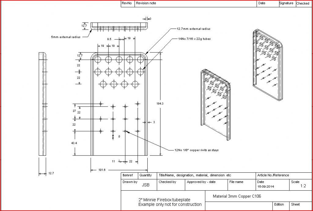
                      If I were looking to be showing a design for approval the drawing would look something like this. I have used the 14No 7/16" tubes you said were suggested in an earlier post, 3mm plate as the nearest available and put what look right stay wise. I don't have the time to calculate it all out so take this as an example not to be used for construction. Click for a larger image, you don't need the 3D images but they can help. It look slike you prefer metric so I have tried to use "whole" metric dimensions where possible but things like the overall size are based on imperial.

                      minnie fire box tubeplate.jpg

                      You can hopefully see that I have (hopefully) included all the items that will allow the inspector to see how the plate will be formed, what from, how many tubes and stays as well as their sizes and positions.

                      Thats enough for now will post a bit more later.


                      J


                      Edited By JasonB on 15/09/2014 17:11:46

                      #163648
                      nigel jones 5
                      Participant
                        @nigeljones5

                        Hi Bob

                        Probably fortunate for you that you didn't get all the responses you first asked for as in my opinion a lot of them are complete nonsence! (You can safely listed no Jason though!!). Unfortunately you cannot simply scale up a boiler design, and there is an awful lot to take into consideration to get it right. Everything pretty much works to mathematical principles and models, so your grasp of formulae and how to apply needs to be sound. The easy route for you is to find an already published set of drawings of a similar sized boiler and adapt it, but even that requires a fair understanding of boiler design. People tend to go overboard with stays, but again there are formulae which dictate the zone of effect relative to stay diameter, plate thickness and so on…all gets very deep!

                        #163654
                        JasonB
                        Moderator
                          @jasonb

                          Right, now that you have got an idea of how to show the results of your alterations a bit of thought as to what needs altering. As fizzy says with a boiler you can't just double everything, one reason is that we are dealing with more than just lengths – if we double the dia of the boiler then the area of say the circular tubeplate will go up by the square so that 4 times larger area and volume will increase by the cube.

                          There are a few other things to consider as well

                          1. Practicality. The 1" design iswas never going to really pull a passenger, at best you can walk alongside so the 50psi working pressure was fine at the time.A 2" Minnie has the potential to pull two adults about on decent ground but things will need to be done to allow it to reach this potential such as higher working pressure which will require the largest grate area possible and best breathing/heating surface.

                          2. Current Regs. Its now prefered to have a separate feed to the pressure gauge rather than take it off the manifold with everything else so allow an extra bush for that. You will also need two means of getting water into the boiler not the single pump as per the 1". Best to allow another bush on teh offside of teh boiler for a clack (non return) valve fed from an injector.

                          3. Availability of materials. We have already mentioned the need to use metric sheet thicknesses so not only will sizes need to be adjusted to suit but all calculations will need to be based on these as they may not be double the old SWG size. Also think abouts whats easily available, your sketches show 11mm tube but thats not as easily obtainable as 7/16" tube so your drawing and calculationsshould reflect whats going to be practical to use

                          4. Design shortcummings. Its a well known fact that the way the Minnie pump mounts on the side of the boiler causes problems as the pump gets hot. Think about having a pump spaced off teh hornplates which does away with teh big bronze pad but you will need another bush for a second clack

                          5. This really links in with practicality. Doubling up the 1/4" x 1/4" foundation ring to 1/2×1/2 gives rather a large water space around the firebox. I would be tempted to go with 3/8" x 3/8" which would give a slightly larger grate area eg bigger fire = more heat.

                          I did give some ideas of tube sizes and numbers in one of your earlier threads. I still feel the 14 7/16" tubes are a bit low, better to add a few more now as you can always close the damper to reduce the rate of burn but not so easy if the fire cannot burn to its full capability if its strangled by too little flue area. I'll sketch out a couple of alternatives later but as an idea of what can be got in there my Fowler has a slightly smaller boiler at 4.75" dia yet has 50% more tubes at 21No vs your 14No.

                          If you intend using this engine then I would also want to add at least one washout plug to the rear corner of the firebox maybe two. If you just leave the one blowdown point it will not be easy to make sure the bottoms of the water legs stay clean of silt.

                          Bit more to follow later but that should give you some idea of the areas you need to consider


                          Edited By JasonB on 15/09/2014 20:12:52

                          #163656
                          JasonB
                          Moderator
                            @jasonb

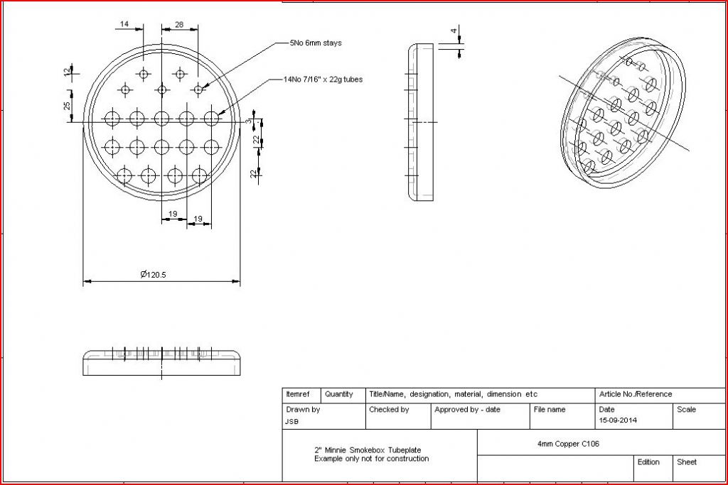
                            Jumping back to the tubeplate for a moment, this is the first drawing I did based on the 14 tube layout as I drew on the firebox plate, shows the bottomtubes came out a bit too close to the edge for my liking but I left as is so as not to confuse things.

                            minnie smoke box tubeplate.jpg

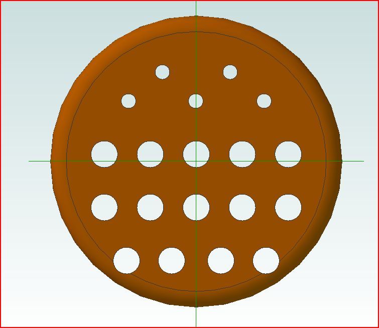
                            And this is what it would look like.

                            tubeplate.jpg

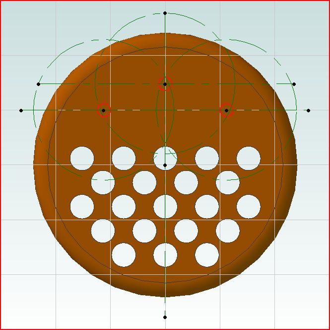
                            If you read my comments on the "copper porn" threads you will have seen that I suggested there were less full length stays because the plate is 4mm thick. John Haining in his book " Countryman's Steam" gives a rough formulat for stay spacing of (thickness x 800) divided by working pressure all in imperial. So taking my suggested 100psi we get 0.157×800 = 125.6 divide that by our 100psi = 1.25" or 32mm for the metrically minded.

                            In the sketch below I have shown just 3 stays with 64mm green rings around them which cover the whole of the plate so no part of teh plate is further than 32mm from a stay. Also shows how easily 22No tubes will fit.

                            tubeplate stays.jpg

                            May add a bit more tomorrow, need to mention the hornpolate stays and where to find the formula for all these calculations

                            J

                            Edited By JasonB on 15/09/2014 20:45:12

                            #163670
                            nigel jones 5
                            Participant
                              @nigeljones5

                              Jason – that's exactly how I demonstrate my stay calculations…you don't need praise but im impressed!

                              #163672
                              Packmule
                              Participant
                                @packmule

                                At last , a sound logical answer as to what and why ,thank you both.

                                The example of using TT ( a site much promoted on ME ) was to try to help promote my point that despite asking I get no replies, and no the messages are not sitting in my outbox. It could well be the older message I sent to a member, is no longer with us. Who knows ?

                                Frustration can and does get to all of us and when you ask and get sparse or no information and you are getting nowhere fast. It gets to the point of what is the point asking because it all seems to be a closely guarded secret and no one wants to let you know.

                                But now I have something to work with and again Thank you for a more in depth reply

                                bob

                                #163705
                                JasonB
                                Moderator
                                  @jasonb

                                  Well seeing as I've got Fizzy's approval wink 2we may as well look at the firebox side stays.

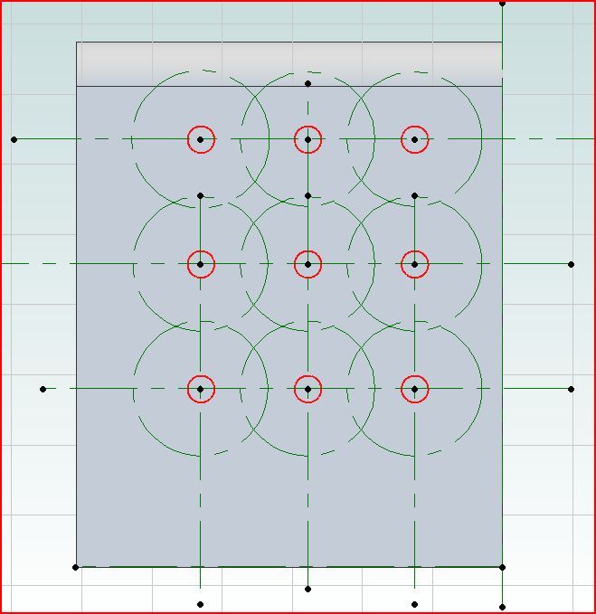
                                  If the dimensions on the 1" drawings are simply doubled then that puts the stays at upto 1.75" apart which does not give the flat sheets a lot of support and they may bulge outwards under pressure. Using the same formula as above of thickness x 100 divide by working pressure we get a maximum stay spacing of 0.118 x 800 / 100 = 0.944" or say 24mm. Using the same circle method shows that not only does the adjacent stay not fall within the circle but whole areas are not covered.

                                  wrapper 2x spacing.jpg

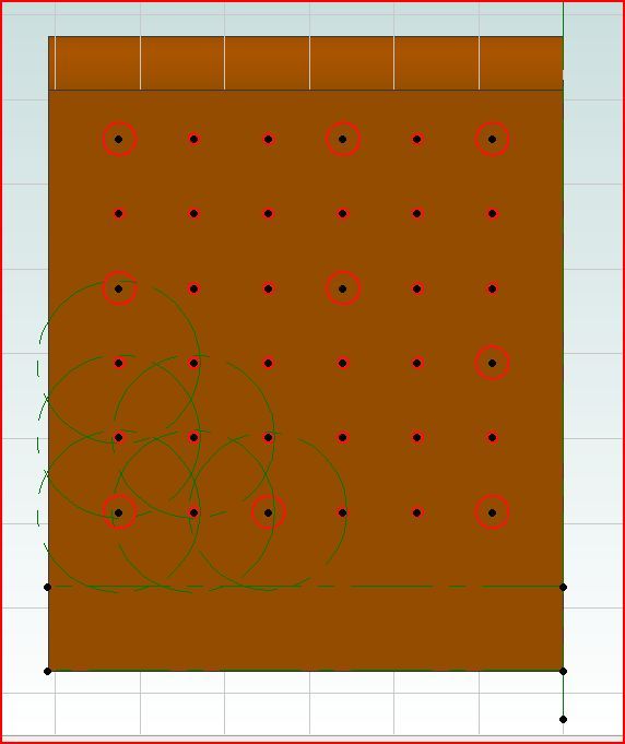
                                  So the stays need to go closer together. 7/8" is quite commonly used on other 2" TE designs so I have laid it out again with a 22mm spacing, most of the stays can just be done with 1/8" rivits but about 9 are needed to hold the hornplates so I have shown those as being made from 3/8 rod. You can now see that the green circles overlap the centre of the adjacent stays and also overlap the level of the foundation ring and where the flanges of the tubeplate and doorplate come.

                                  wrapper 22mm spacing.jpg

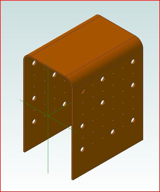
                                  And how the bent sheet will look

                                  wrapper 3d.jpg

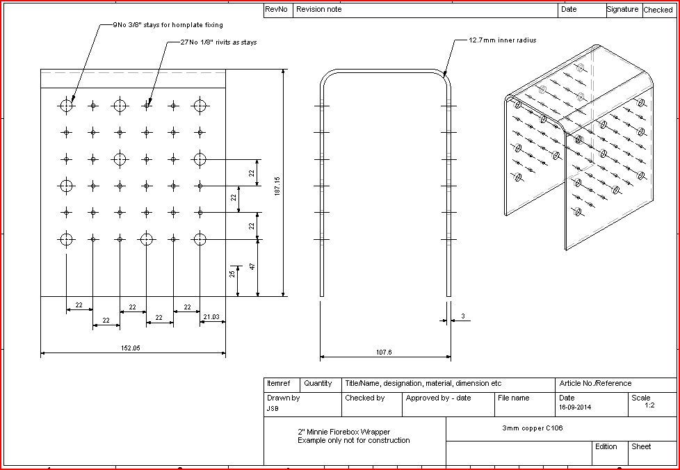
                                  And the drawing so your inspector can see the actual dimensioned spacings

                                  firebox wrapper.jpg

                                  You will see that I have been refering to using copper roivita as stays rather than threaded stays which are not used that much these days. The rivits don't have to have a head formed on teh plain end, just push them into the pair of holes and slightly bend the excess end which will stop the rivit falling out while you solder it, the excess can be cut of afterwards.

                                  For the larger stays that the hornplates fix to I would use i=either copper or bronze round bar 3/8" or 10mm dia. Part of 18No and drill 3.3mm allowing about 1mm to stand proud inside the firebox and 5mm on the outside. After soldering the boiler can be packed up true on its side on teh mioll table and the 5mm ends milled down level. Rather than leaving them 1/8" (twice the 1/16 brass nut from the 1" drawings) work out whats needed to make the outside of teh now metric 3mm hornplates measure 5.75".

                                  The 3.3mm hole will then give you the option to tap it M4 or open out to 4mm. If you use M4 button head screws they will look like rivits, either with a nut on the inside if drilled 4mm or better still the tapped hole will allow you to screw into the stay and use a locknut (not nyloc!! ) inside the firebox to make sure the screws don't come loose

                                  Bit more later

                                  #163706
                                  JasonB
                                  Moderator
                                    @jasonb

                                    Well seeing as I've got Fizzy's approval wink 2we may as well look at the firebox side stays.

                                    If the dimensions on the 1" drawings are simply doubled then that puts the stays at upto 1.75" apart which does not give the flat sheets a lot of support and they may bulge outwards under pressure. Using the same formula as above of thickness x 100 divide by working pressure we get a maximum stay spacing of 0.118 x 800 / 100 = 0.944" or say 24mm. Using the same circle method shows that not only does the adjacent stay not fall within the circle but whole areas are not covered.

                                    wrapper 2x spacing.jpg

                                    So the stays need to go closer together. 7/8" is quite commonly used on other 2" TE designs so I have laid it out again with a 22mm spacing, most of the stays can just be done with 1/8" rivits but about 9 are needed to hold the hornplates so I have shown those as being made from 3/8 rod. You can now see that the green circles overlap the centre of the adjacent stays and also overlap the level of the foundation ring and where the flanges of the tubeplate and doorplate come.

                                    wrapper 22mm spacing.jpg

                                    And how the bent sheet will look

                                    wrapper 3d.jpg

                                    And the drawing so your inspector can see the actual dimensioned spacings

                                    firebox wrapper.jpg

                                    You will see that I have been refering to using copper rivits as stays rather than threaded stays which are not used that much these days. The rivits don't have to have a head formed on teh plain end, just push them into the pair of holes and slightly bend the excess end which will stop the rivit falling out while you solder it, the excess can be cut of afterwards.

                                    For the larger stays that the hornplates fix to I would use either copper or bronze round bar 3/8" or 10mm dia. Part of 18No and drill 3.3mm allowing about 1mm to stand proud inside the firebox and 5mm on the outside. After soldering the boiler can be packed up true on its side on the mill table and the 5mm ends milled down level. Rather than leaving them 1/8" (twice the 1/16 brass nut from the 1" drawings) work out whats needed to make the outside of the now metric 3mm hornplates measure 5.75" overall width.

                                    The 3.3mm hole will then give you the option to tap it M4 or open out to 4mm. If you use M4 button head screws they will look like rivits, either with a nut on the inside if drilled 4mm or better still the tapped hole will allow you to screw into the stay and use a locknut (not nyloc!! ) inside the firebox to make sure the screws don't come loose

                                    Bit more later

                                  Viewing 16 posts - 1 through 16 (of 16 total)
                                  • Please log in to reply to this topic. Registering is free and easy using the links on the menu at the top of this page.

                                  Advert

                                  Latest Replies

                                  Home Forums Beginners questions Topics

                                  Viewing 25 topics - 1 through 25 (of 25 total)
                                  Viewing 25 topics - 1 through 25 (of 25 total)

                                  View full reply list.

                                  Advert

                                  Newsletter Sign-up