Hi all,
I have been researching the Stephenson locomotive “Lancashire Witch” for development as a 7 1/4″ gauge model for about a year now but have come up against a detail problem regarding the boiler feed pump.
This, as on many locomotives from around 1830, is driven by a crosshead coupling and the delivery is via a ram pump, so far so good.
On these early engines however the pump itself consists of typically two vertical barrels linked together with the boiler linking to the top of the uppermost barrel. Two cocks are provided, one on each barrel and I have been completely unable to find out exactly what goes on within.
Ball valves came a bit later than Lancashire Witch so the lack of space for a ball in the vicinity of each cock is not a problem, almost certainly some form of lifting plug valve is performing the same function. The problem is that any control of boiler feed seems to be almost impossible without a severe danger of hydraulic lock.
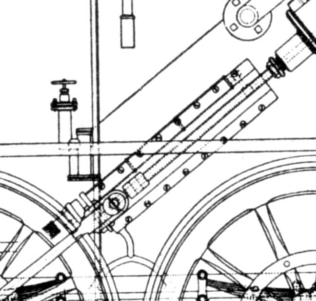
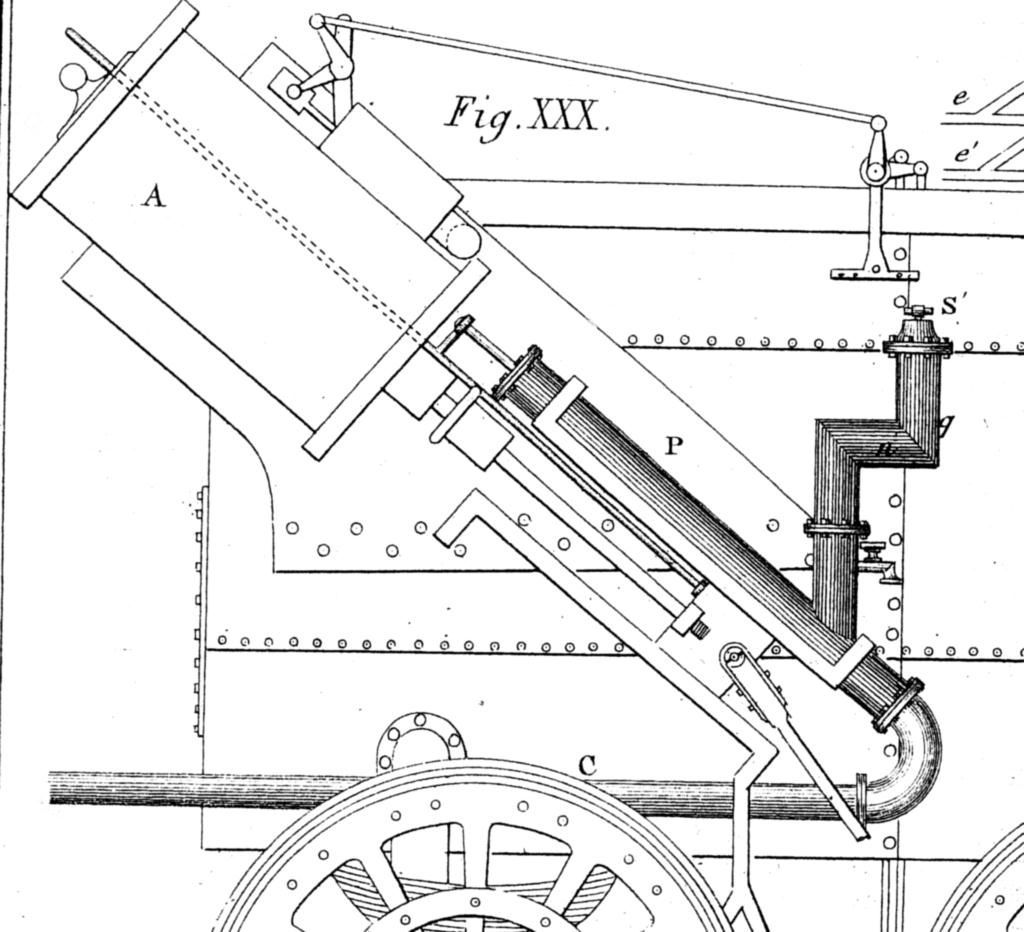
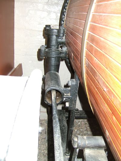
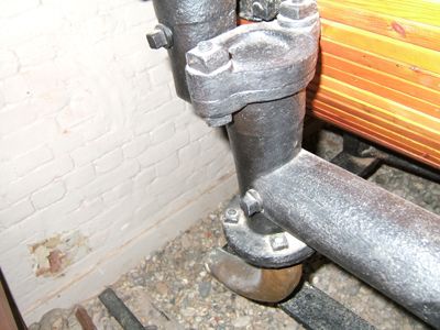
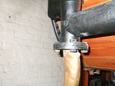
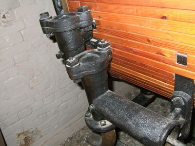
I have found three depictions of the same form of feed pump, two from drawings and one in the flesh, on “Invicta” in the Canterbury Museum but no indication of the appropriate innards. The NRM did not seem able or willing to help (although I think Invicta may have been disassembled in part for restoration) and the only other place that seems to understand really early locomotives, the Beamish museum, also presented a deafening silence.
I can post some files of the evidence to date but someone may know the answer, please wade in.
Many thanks,
Jonathan Howes.
John Olsen.


