A little bit on the side

Advert

A little bit on the side

Home Forums Work In Progress and completed items A little bit on the side

Viewing 4 posts - 1 through 4 (of 4 total)
  • Author
    Posts
  • #808923
    JasonB
    Moderator
      @jasonb

      About a week ago I got an email from a Guy I have made engines for in the past asking if I would be interested in helping him out with a flywheel.

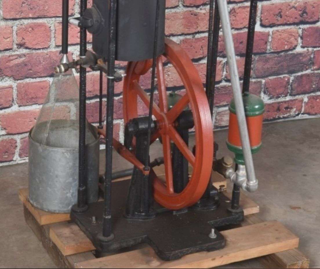
      He is part way through the build but the flywheel casting has several problems, where have I heard that before? Firstly it is cast from aluminium rather than iron. The two halves are misaligned by 3mm. Both the rim and the spokes are excessively heavy when compared to photos of the original, this may be to compensate for the use of aluminium. The flywheel has a large balance weight but this is supplied as a separate casting to be screwed on not an integral part of the casting requiring drilling through the face of the rim to fix it.

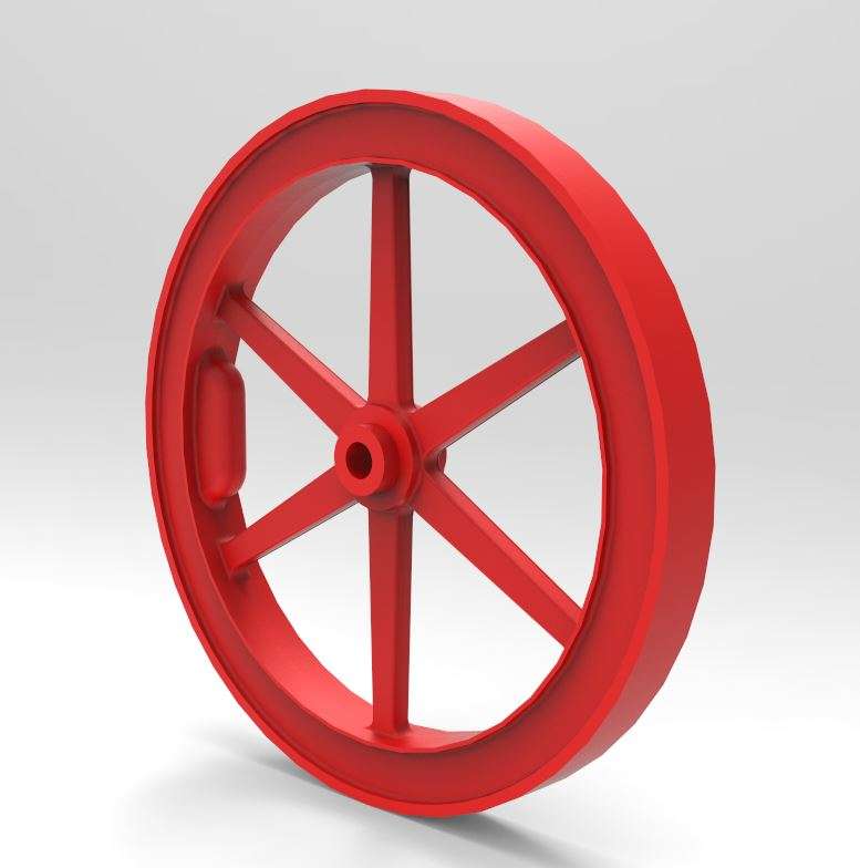
      Being the chap that I am my reply was I should be able to help, let me have more details. Over a few evenings a new flywheel was developed based on some images he sent me and about 20 screen shots that I senyt back until a design that was acceptable was arrived at. Still slightly wide at teh rim but as the scale goes down you need a bit more mass at the rim but not as thick as the original drawings.

      flywheel render

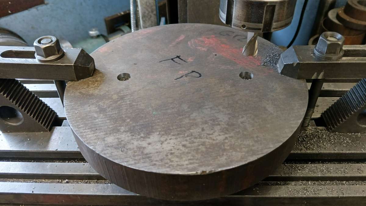
      A slice of 190dia cast iron bar was ordered from M0-machine along with some other materials that I wanted and today I made a start roughing it out. I had ordered a 25mm long piece but it was closer to 29mm so a fair bit of searf to get it down to 23mm overall thickness then 18mm at the rim. Two 6mm holes were counterbored from both sides so I could screw it into some previously tapped holes in my faceplate.

      20250724_134934

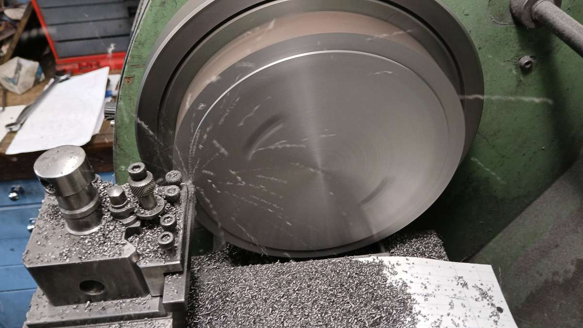
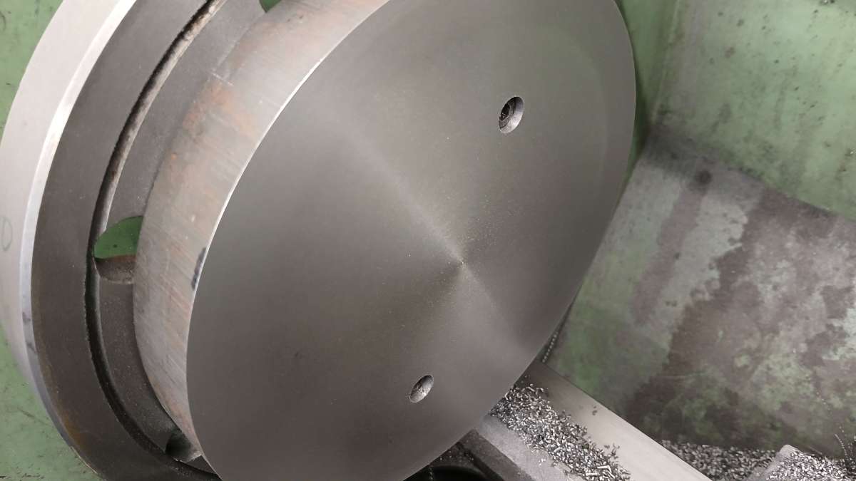
      I took a light skim off the first side then with that against the faceplate took some heavier cuts to start bringing the thickness down. 300rpm, 1.25mm depth of cut with a CCGT060202 “spare corner”

      20250724_141706

      Not too bad a roughing cut

      20250724_142517

      Advert
      #808924
      JasonB
      Moderator
        @jasonb

        I forgot to add an image of the original

        Screen Shot 08

        #809519
        JasonB
        Moderator
          @jasonb

          I got the remaining turning work done which consisted of reducing the thickness to leave a small spigot which will become the wider hub. I also cut the recess in each sid eof the flywheel rim, this was done with a combination of round ended brazed carbide tool, boring bar with 060208 insert and a left hand tool with a similar insert.


          20250725_143744

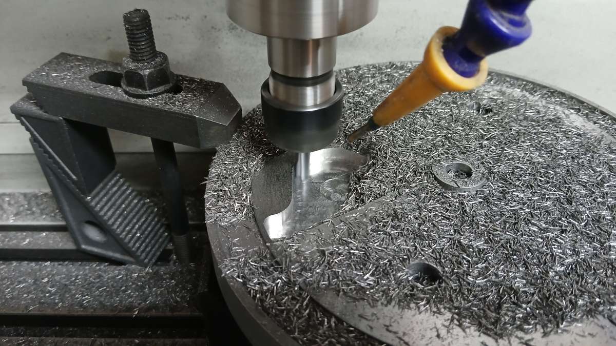
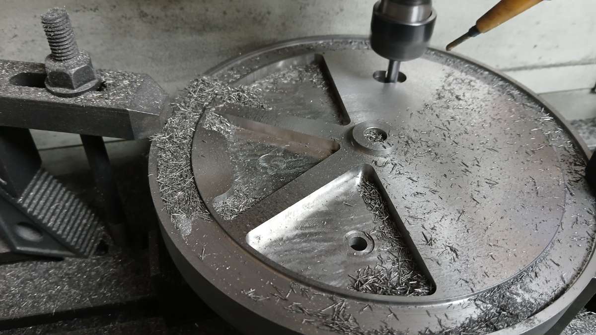
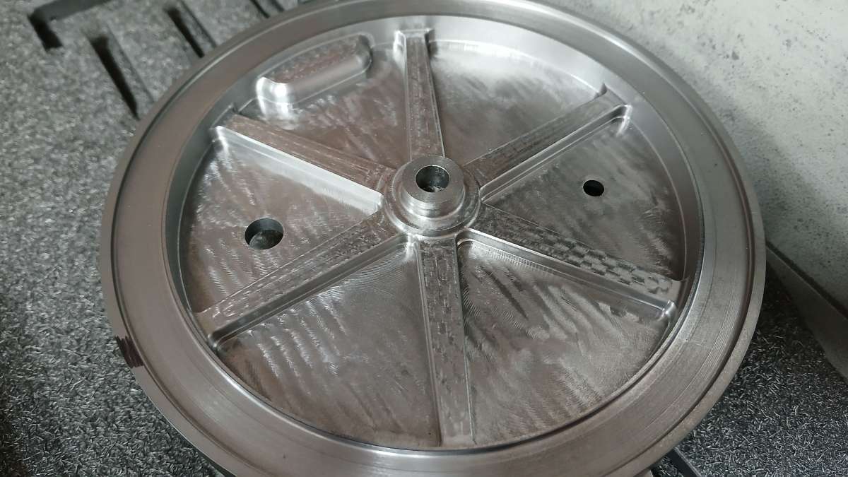
          Moving over to the CNC I started with an Adaptive path to remove the majority of the material down to 2/3rds the depth with a 6mm 3 flute cutter

          20250728_091434

          20250728_093522

          20250728_120625

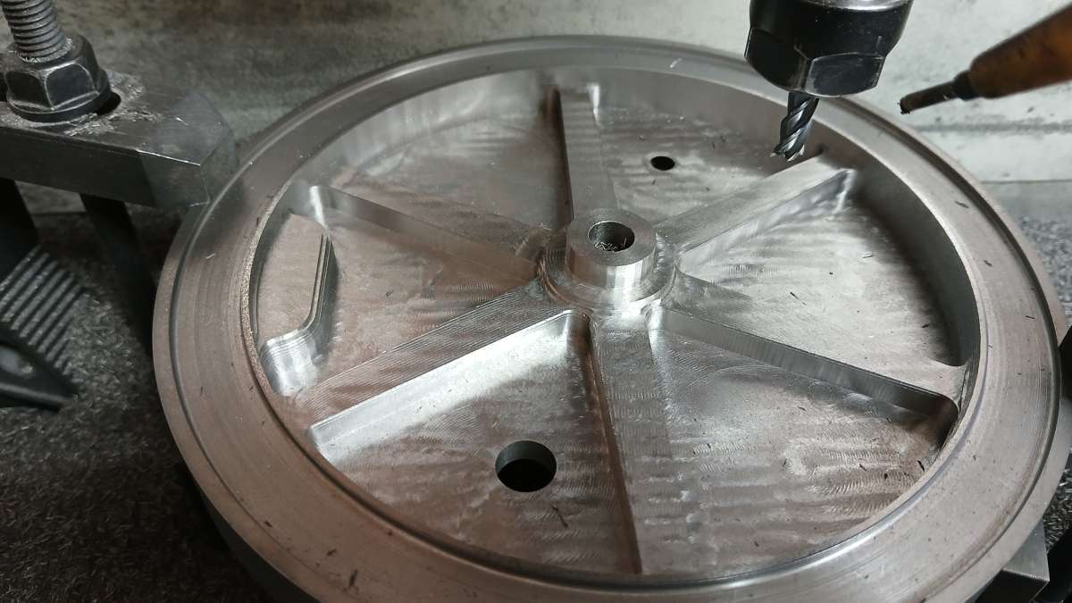
          I then used a “ramp” path for the near vertical inner edges of teh rim and spokes a sthey had 3degrees draft. Followed this by a horizontal path to finish the tops of teh spokes and balance weight.

          20250728_145752

          Anyone care to have a guess at the final weight, the slice started off at 5.82kg which is about 13lbs? I should have the answer tomorrow.


          #809521
          Diogenes
          Participant
            @diogenes

            1800g?

          Viewing 4 posts - 1 through 4 (of 4 total)
          • Please log in to reply to this topic. Registering is free and easy using the links on the menu at the top of this page.

          Advert

          Latest Replies

          Viewing 25 topics - 1 through 25 (of 25 total)
          Viewing 25 topics - 1 through 25 (of 25 total)

          View full reply list.

          Advert

          Newsletter Sign-up