Beginner needs help with Colchester Bantam Lathe

Advert

Beginner needs help with Colchester Bantam Lathe

Home Forums Help and Assistance! (Offered or Wanted) Beginner needs help with Colchester Bantam Lathe

Viewing 25 posts - 1 through 25 (of 43 total)
  • Author
    Posts
  • #32574
    Paul Matthews 4
    Participant
      @paulmatthews4

      Single phase motor problems

      Advert
      #205023
      Paul Matthews 4
      Participant
        @paulmatthews4

        Hi everybody, this is my first posting, so a bit of background, for the past two years or so I've had a Chester 920 lathe for odd jobs, but have always wanted to get a bigger lathe which can do more things, so after doing a bit of research I've gone for a Colchester Bantam (Mk1 I think) – as it was just for domestic use I needed a single phase motor, so found one and it's now in my garage. It needs a bit of work on it to tidy up a few bits but I am very impressed with the quality of the build and the smooth action of the feeds. However, I do have one issue, as it is a single phase motor, I can only use one set of speeds – not really a problem to me, but when running the motor at the highest chuck speed of 800rpm, the motor continually cuts in and out (that's what is sounds like) as if it's overloading and shutting down. It runs at all speeds below 800rpm fine and even fine at 800rpm in reverse. Could anybody offer a reason for this? I've got a short vid here so you can see what I mean: **LINK**

        Regards

        Paul

        Edited By JasonB on 20/09/2015 11:40:16

        #205040
        Muzzer
        Participant
          @muzzer

          What (power) motor have you got on there? Almost sounds as if the starter is kicking out before it's up to speed and then it doesn't have enough oomph to get it from there all the way up to full speed.

          Single phase motors won't start up without help from a starter circuit. Personally I would have left the original 3-phase motor where it was and added a small VFD.

          Have you tried loading it up ie taking a cut / making some swarf? It may be so under powered it would cut out.

          Nice machine. I have a Bantam too. Now you need to start collecting all the accessories!

          Have you got the manual / parts list etc? I have them if you want to PM me.

          Murray

          #205041
          Bob Brown 1
          Participant
            @bobbrown1

            I do not think a small VDF would work with the original motor as that would have been dual speed hence the two speed ranges, it would have been possible to run it on a VDF but the output will need to be 415v 3 phase. Been done before on here with a unit from Direct drives now who was it **LINK**

            Nice machine, what size is the motor as probably needs a larger single phase motor that the original 3 phase motor something around 1.5 to 2hp .

            Bob

            #205042
            Ian S C
            Participant
              @iansc

              Paul, I see that the motor power for these lathes is 0.9 kW for the low speed, and 1.3 kW for the high speed version, with a single phase I go for 1.5 kW/2 hp. I think you'r getting too much drag through the gears on start up, and not getting full speed before the start winding cuts out. I'd agree with Murray about keeping the three phase motor, although except with a lot of cash you can't have two speed. The three phase has better starting torque, and runs smoother, sort of comparing a V 8 with a lawn mower.

              My slightly larger Taiwanese lathe has a 1.5 hp sp motor, and at times I'd like a bit more, but it's a belt head, and it slips the belt as it is.

              Ian S C

              Edited By Ian S C on 20/09/2015 13:17:55

              #205043
              Paul Matthews 4
              Participant
                @paulmatthews4

                Thanks everybody for the prompt feedback, time is against me as I had to get the lathe back home before I go on holiday, so unfortunately I can't have a play under load but fortunately, my retired engineer dad is coming down so I've asked him to take a look. I can see the motor plate (an old English motor by the looks of it) but it is at the bottom and partially hidden by the tray so I need to move the lathe away from the wall to see it (no big deal as it's not in its home yet) but just haven't got the time to do it until I get back from hols.

                Murray, very kind for the offer, I got the manual (photocopied) with the lathe which is a nice bonus.

                Will report back when we know more.

                Many thanks

                Paul

                #205045
                Keith Long
                Participant
                  @keithlong89920

                  Paul – your lathe seems to get up to speed when you run in reverse, which suggests to me that the motor is basically powerful enough but something is definitely amiss in the forward direction. Can you measure the peak speed that it reached running forwards on the 800 rpm setting? What supply side wiring have you got to it – I think I'd be looking to see if everything is OK there before delving much further into the motor.

                  If the machine was originally 3 phase you might have 2 contactors to start it, one for forward and one for reverse, with the forwards/ reverse switch selecting which one to use, rather than effectively swapping the motor leads. If that is the case then check the current overload setting on the forward contactor it could be set too low. The fact that the motor runs OK in the forward direction at the lower speeds (less current drawn) suggests that the contactor (if fitted) is holding in OK. Looks as though you need to consider everything from the mains input right through to the motor.

                  #205051
                  Muzzer
                  Participant
                    @muzzer

                    No, it just has (had?) a reversing (changeover) switch. If an overload occured, the starter would completely drop out, so that isn't a valid theory.

                    Sounds as if there is a centrifugal switch that is dropping out before it is turning fast enough to keep going up to speed. Once the speeds falls, the centrifugal switch kicks in again and the starter circuit is energised. Centrifugal switches have hysteresis, hence the cycling.

                    Not clear why reverse should be any different but it may simply be very marginal – hence my question about how it behaves under some kind of load.

                    #246727
                    Paul Matthews 4
                    Participant
                      @paulmatthews4


                      Hi there everybody I've been given a much more modern A/C motor that I wanted to try out and see if I could solve the problem of the stall at top speed as above. Unfortunately, not knowing much about electronics I'm a bit stumped now, so I'd like to ask if anyone can advise:

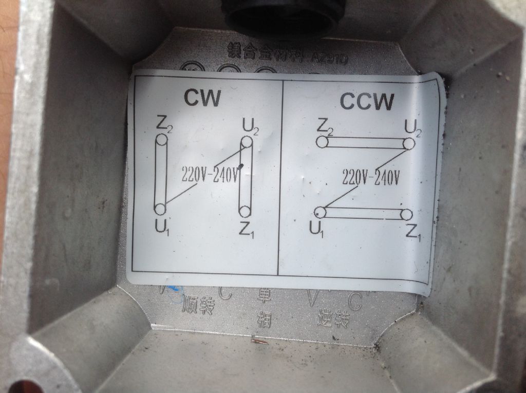
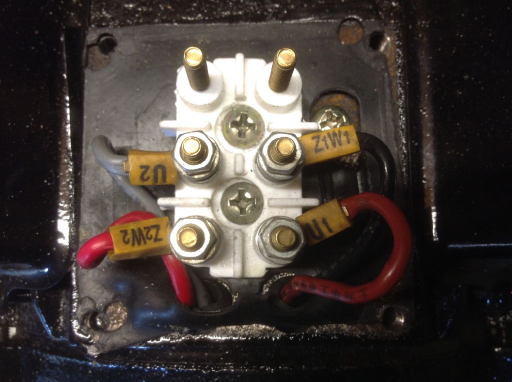
                      My existing arrangement has a single phase motor fed by three wires, which (I think this is right) are two lives and a common neutral. One live operates the motor in clockwise and the other counterclockwise, these bring switched by the forward / reverse control on the lathe. The new motor has a different arrangement as per the wiring diagram below

                      image.jpeg

                      image.jpeg

                      This indicates the wiring required to operate the motor in clockwise and counterclockwise directions by the use of physical links – obviously I need to operate this via a switch control so I can operate the motor in both directions without the physical links. I spoke to a technician at the motor manufacturer and he confirmed the motor was used on one of their lathes so is suitable for my needs and in order to operate the motor via the forward / reverse control on the lathe, I'd need to add two contractors to the existing three wire supply. Well I'm a bit stumped now as to how to do this, I'd be grateful if anyone could offer any advice.


                      Edited By Paul Matthews 4 on 15/07/2016 19:27:29

                      #246731
                      Martin Connelly
                      Participant
                        @martinconnelly55370

                        To reverse this motor use a double pole double throw contactor. Each pole will have common, normally closed and normally open terminals. COM1, NO1, NC1, COM2, NO2, NC2. Connect U1 to COM1, U2 to COM2, Z1 to both NC1 and NO2, Z2 to both NO1 and NC2. In this setup with the contactor de-energised you will get CCW and energised you will get CW. A second run contactor is used to apply power to the reversing contactor common terminals.

                        Martin

                        #246738
                        Neil Wyatt
                        Moderator
                          @neilwyatt
                          Posted by Muzzer on 20/09/2015 14:43:27:

                          No, it just has (had?) a reversing (changeover) switch. If an overload occured, the starter would completely drop out, so that isn't a valid theory.

                          Sounds as if there is a centrifugal switch that is dropping out before it is turning fast enough to keep going up to speed. Once the speeds falls, the centrifugal switch kicks in again and the starter circuit is energised. Centrifugal switches have hysteresis, hence the cycling.

                          Not clear why reverse should be any different but it may simply be very marginal – hence my question about how it behaves under some kind of load.

                          The geometry is subtly different depending on rotational direction – one way any sudden decrease in speed may tend to close the switch more than in the other.

                          Neil

                          #246783
                          frank brown
                          Participant
                            @frankbrown22225

                            I feel that the start/ run switch could be a red herring. I would check the motor drive train including the gear box. The lathe would have been run in forwards for 90% of its life so bearings would be worn in this direction. When the drive train is in reverse, a different area of the bearings (unworn?) would be used. Could be interesting to measure the motor current to see if the load is the same. Oil pump efficiency in forward and reverse?

                            Have you put your hand on the motor and felt the surge as the start/run switch cycles? My immediate impression was that the gear box was slipping in high speed forward, can't hear the motor.

                            Frank

                            #246803
                            Simon Williams 3
                            Participant
                              @simonwilliams3

                              Motor is underpowered. With the start winding energised it has enough torque to accelerate the machine from standstill, but then the centrifugal switch opens (at about 70% full speed or thereabouts) and the motor now hasn't got enough torque to continue accelerating the gear train etc up to full speed. So the motor begins to stall, and slows until the start winding is energised again by the centrifugal switch where it begins to accelerate.

                              Solution is a bigger motor, or don't use the 800 rpm range. Maybe this isn't the original motor – someone maybe converted it from three phase but fitted an undersized motor?

                              As Neil says, it's just a quirk of the internal geometry of the motor that it will develop enough torque to run to full speed in reverse but not forward. Single phase motors are like that. The gearbox sounds fine, I wouldn't go investigating the bearings, that's just a can of worms which is probably irrelevant for the time being.

                              We'd still like to know what the motor rating plate says is the rated power of the motor. I've got a Bantam 2 with a 1.0 HP motor, that's not got enough oomph to run at 2000 rpm but otherwise it's fine.

                              Measuring the supply current on a single phase motor isn't going to resolve anything, you would need to measure power factor as well, as the current stays very nearly constant as the motor is loaded, it's the power factor that changes in response to the shaft load. Also the supply current changes drastically as the start winding cuts on and off so measuring the supply current under running conditions is far from straightforward.

                              Lovely machine – lots of good work here even if the top speed is outside its capabilities for the time being,

                              HTH Simon

                              #246885
                              Paul Matthews 4
                              Participant
                                @paulmatthews4

                                Hi everyone thanks once again for the comments – plenty of food for thought – unfortunately the motor plate is right under the motor so very difficult to see but I'll try now I've moved the lathe out from the wall – be in touch…

                                #247183
                                Paul Matthews 4
                                Participant
                                  @paulmatthews4

                                  Yes this was a 3 phase motor originally but converted to single phase motor which is 2850rpm, 2hp – can just about read it on the plate which is underneath

                                  Edited By Paul Matthews 4 on 18/07/2016 21:01:31

                                  #247188
                                  Nick_G
                                  Participant
                                    @nick_g
                                    Posted by Paul Matthews 4 on 18/07/2016 20:58:31:

                                    Yes this was a 3 phase motor originally but converted to single phase motor

                                    Edited By Paul Matthews 4 on 18/07/2016 21:01:31

                                    ,

                                    Are you sure. Or is it a dual voltage 3 phase motor.?

                                    Don't be taken in that it 'says' 220v. That maybe 220v 3 phase.

                                    Nick

                                    Edit :- Scratch that I have just read the whole thread and it's associated images. blush

                                    Edited By Nick_G on 18/07/2016 21:45:21

                                    #247190
                                    Simon Williams 3
                                    Participant
                                      @simonwilliams3

                                      Hi Paul,

                                      Well, I was totally confident that the nameplate would show the motor was half horse power or thereabouts, and we could put this to bed. Shows how much I know! 2 HP should be plenty.

                                      However, there are a couple of questions that arise out of the information you have posted, as I fancy the original motor would have run at 1450 rpm, and this motor runs at twice that speed. Do you have a means of measuring the ACTUAL speed at the chuck, not just what the gear lever nameplate says? I just wonder if the whole thing is running at twice the speed indicated, unless whoever did the conversion did the right thing and altered the pulley sizes appropriately. If we're actually running at 1600 rpm then 2HP on a single phase motor might well be marginal. I can't gauge the speed from the video.

                                      My second question is just to confirm the full load current as indicated on the motor name plate, just to check that it correlates with that of a 2HP 230 volt single phase motor. If you can get a piccy of the nameplate so much the better.

                                      Failing that my next best theory is that there is something odd with the motor run winding, though I can't fit that with the proper operation at lower speed at the moment.

                                      Mmm. Interesting. The thick plottens.

                                      Rgds Simon

                                      #247191
                                      Simon Williams 3
                                      Participant
                                        @simonwilliams3

                                        Hello again, could someone who knows about the innards of single phase centrifugal start motors comment on this for a hypothesis please?

                                        If the start and run windings were correctly connected in reverse, but somehow swapped in forwards, would this explain what we're seeing?

                                        Rgds Simon

                                        #247192
                                        Paul Matthews 4
                                        Participant
                                          @paulmatthews4

                                          HI Simon

                                          Yes I can check the chuck speed with a meter – I'll also try and get a photo of the plate tomorrow, i'll double check the HP – not easy to see, 1/2 could look like 2! Regards Paul

                                          Hi Nick

                                          I think this is right, this lathe originally had a 2-speed control (as per the blue/red plate you can just see in the vid) – I think that was only available for a 3-phase supply but could be wrong. The two-speed switch has now been removed so only the speeds on the red part of the plate now apply. Regards Paul

                                          #247196
                                          Bob Brown 1
                                          Participant
                                            @bobbrown1

                                            The original motor would have been two speed 3 phase working 2 pole and or 4 pole to give the different speeds e.g. 2600/1400 rpm. and something around 1.5hp on full speed (1600 rpm spindle speed).

                                            #247210
                                            not done it yet
                                            Participant
                                              @notdoneityet

                                              There is a clear click when a bench grinder runs down and the start winding contacts remake. Quite possibly the OP might hear this continual clicking in and out for the start windings if one's ear can be positioned close enough to the motor?

                                              It may be that the start winding contact springs are aged or worn? Changing them might effect a cure, but there is always the risk that the start windings may not be disconnected at full speed in the reverse direction and result in a motor burn out.

                                              The cross-over points for 2 and 4 pole motors and required starting torques are discussed in this link, and may be of help (but I doubt it smiley!

                                              http://www.engineeringtoolbox.com/electrical-motors-torques-d_651.html

                                              I don't know enough about motors, but I do know I prefer 4 pole to 2 pole varieties!

                                              #247220
                                              Paul Matthews 4
                                              Participant
                                                @paulmatthews4

                                                Hi guys,

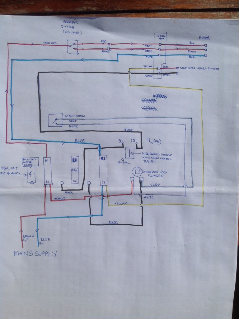
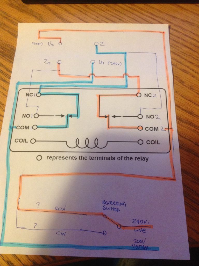
                                                I'm going to try this new motor I've got, just to see if it solves the cut out problem – Martin, you kindly gave me details of how to wire it up, I've sketched out the wiring below, afraid I don't know much about electronics and not sure how I run the second contactor can you help – the existing reversing switch is an electro-mechanical switch operated from a lever close to the lathe saddle – which is extremely handy and I do not want to loose it – so if I have understood the wiring correctly (sketch of lathe wiring as below based on my limited understanding of electronics) this lever simply switches between two 240v outputs shown as red and brown on my sketch. One of these will need to energise the coil for the switch from CCW to CW to work – so I'd appreciate advice on where I need to locate a run contactor and how it should be wired. Many thanks once again. Paul

                                                photo 18-07-2016, 18 01 32.jpg

                                                photo 18-07-2016, 22 24 31.jpg

                                                #247225
                                                Paul Matthews 4
                                                Participant
                                                  @paulmatthews4

                                                  Photo of motor plate as best I can take. Checked chuck speeds and a bit faster than prescribed:

                                                  334rpm actually running at about 360rpm

                                                  510rpm actually running at about 560rpm

                                                  photo 19-07-2016, 10 54 06.jpg

                                                  #247229
                                                  Martin Connelly
                                                  Participant
                                                    @martinconnelly55370

                                                    The forward/reversing switch should energize the coil and should not go to com2, com2 should be wired directly from A1. You do not seem to have a 24V control system so you need a contactor that has a coil designed for mains voltage. One side of the coil is connected directly to the C1 terminal and the other side to A1 through the forward/reverse switch. You should only have the two wires going to the reversing switch. Put the wire from A1 to the common terminal of the forward/reverse switch. If you find forward and reverse are the wrong way round then swap the wire going to the coil to the other terminal of the forward/reverse switch.

                                                    Martin

                                                    #247230
                                                    Bob Brown 1
                                                    Participant
                                                      @bobbrown1

                                                      Has the drive pulley been changed? as a motor running at 2850 should give the higher speed range rather than the lower range.

                                                    Viewing 25 posts - 1 through 25 (of 43 total)
                                                    • Please log in to reply to this topic. Registering is free and easy using the links on the menu at the top of this page.

                                                    Advert

                                                    Latest Replies

                                                    Viewing 25 topics - 1 through 25 (of 25 total)
                                                    Viewing 25 topics - 1 through 25 (of 25 total)

                                                    View full reply list.

                                                    Advert

                                                    Newsletter Sign-up