The shunt is as has been said to provide a degree of protection – both to the magnetron and the transformer by providing current limiting. When current flows in the secondary, an opposing magnetic field is set up in the transformer core. This reduces the induction in the secondary, and therefore output voltage. This is overcome when there is only one magnetic path, and so all the primary flux cuts the secondary winding, and current is then only limited by the winding resistance ( and AC impedance which we will ignore for this discussion)
However, if a second flux path is provided – the 'shunt'- The secondary generates the opposing magnetic field, the strength of which depended on load current, but the Primary flux wishes to be maintained, primary flux is forced to pass more and more through the shunt, and less through the secondary leg, hence output voltage drops as does current, and a balance is achieved.
This is easily seen in the inexpensive buzz-box stick welders – these often use normal E-I core laminations, with the primary and high-amperage secondary windings on the center leg of the E laminations. All flux cuts the secondary all the time, current is max and limited only by wire and cable resistances. Typically the hi-current secondary open circuit voltage is 18 to 26 volts.
The lower current winding are in series with the high current primary and wound on one of the outer legs of the E laminations. The resulting voltage is higher – from 30 volts up to even 50 volts. This ensures a good arc is struck at the start. But then, after the arc starts, the current flow in the outer leg secondary generates an opposing flux which forces a portion of the primary flux to flow in the opposite leg of the E core, and not in the secondary leg, so dropping the secondary voltage an current.
( Contrary to intuition, the HIGHER the secondary voltage in the outer leg windings, the LOWER the secondary current – this is because the high voltage strives to force a high weld current, which in turn generates a higher opposing flux, forcing the voltage to drop and current with it.)
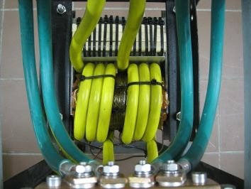
Here I converted a buzz-box core to a 5000 ampere spot welder – the core is simply a square core , similar in operation to a toroidal core, and as a buzz-box welder it had a shunt across the center which I removed. The secondary winding are over the primary. The white upper section with the black stripes are pieces of wood held in place with tie-wraps to stop the core laminations buzzing ( its a buzz box..) at high currents!
The yellow cables are 20mm diameter, two in parallel and in the central part of the core they occupy the space where the shunt sat.
The core is not ideal – it has lots of leakage – desirable in cheap stick welders to have some sort of welding 'control' in lieu of proper current regulation ( variable saturable inductors, etc) and so does not provide best performance in a spot welder application. You want the best magnetic coupling ( secondary under the primary, tight wound) , good silicon steel laminations, properly insulated ( lacquer/varnish) , very low resistance in the weld current path ( only copper, no brass, steel, aluminium, etc).
I have 3.8v at no load on the secondary – at 5000 amps flowing the voltage drops to 2 volts typically, at the weld, and is 3.2volts at the ens of the yellow secondary wires – 1 v is lost in the rest of the cables, the weld arms, connections, etc – thats only 0.2 milliohms!!! Resistance rules in a spot welder!

All very long winded,
The bottom line is if you leave that shunt in place, you will a Spot Welder Not Make…
And Removing it will raise the primary magnetisation current a fraction but can be ignored.
Joe
Edited By Joseph Noci 1 on 26/01/2021 06:38:29
Douglas Johnston.


