

New Myford Speed 10 Spindle
New Myford Speed 10 Spindle
- This topic has 8 replies, 4 voices, and was last updated 3 March 2014 at 03:08 by
 “Bill Hancox”.
 “Bill Hancox”.
 “Bill Hancox”
 Rick Kirkland 1
 Michael Gilligan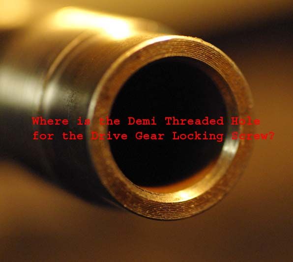
 blowlamp
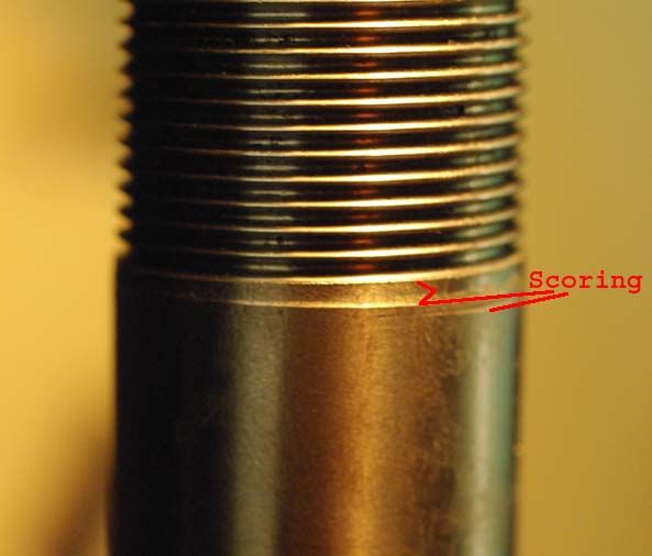
 I finished installing the new spindle last night and I am thoroughly pleased with it. I still need to carry out my final preloading and run up. I have not yet checked the spindle with my ten thou indicator but after snugging up the bearings my one thou indicator shows a very, very slight quiver on the register and there is no needle movement at all on the register face. I have not yet checked the MT run out. In the top photo you can see the machining marks on the end of the spindle. I removed these with a diamond lap. This provided me with a nice smooth surface for the drilling process. The burrs on the scoring behind the threads in the bottom photo were removed with a 1/4" square hard Arkansas stone. I am a bit fussy about such things.
  I had problems installing the grub screw thanks to my inadequate planning. BTW, a faceplate makes good base for doing vertical work on spindles. I simply threaded the new spindle onto the back of the faceplate which enabled it to sit nicely flush on the base of my drill press. I then turned the drill table 90 Deg and packed the spindle plumb and centered under the quill. To enable the drive gear to be dead level with the end of the spindle, I installed the threaded locking ring under the gear and used it to make the necessary adjustments up and down. Then I easily but carefully oiled and drilled the hole using a # 21 bit to suit the 10-32 grub screw that I intended to use. Using a new 10-32 taper tap and oil, I then started the thread. I followed this with a bottoming tap to extend the thread. All of a sudden …snap!! No, not a broken tap. I am now the proud owner of a broken drive gear. Oh well, part of the learning curve. Once I acquire another gear I will revisit this job using 6-32 tooling. I plan to turn a T-shaped steel drilling jig that will fit the bore of the outer end of the spindle. I will also accurately locate and drill the appropriate pilot hole. Whereas the spindle is now installed, intend to use my hand drill.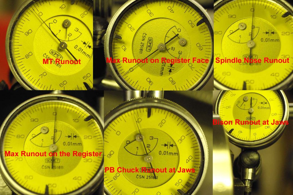
- Please log in to reply to this topic. Registering is free and easy using the links on the menu at the top of this page.
Latest Replies
-
- Topic
- Voices
- Last Post
-
-
Have I got 12-28 UNF wrong or has Völkel?
Started by:
Bill Phinn
in: Workshop Tools and Tooling
- 7
-
15 September 2026 at 07:08
Hollowpoint
-
Ideas needed for problem wth Tom Senior E type Mill
Started by:
Mike Crossfield
in: Manual machine tools
- 2
-
15 September 2026 at 03:27
Pete
-
Drive coil ampere turns for seconds pendulum
Started by:
carlw
in: Clocks and Scientific Instruments
- 3
-
15 September 2026 at 01:09
carlw
-
Myford ML7 Motor
Started by:
ian Holdsworth
in: Manual machine tools
- 2
-
14 September 2026 at 23:40
Nigel Graham 2
-
… I had hoped we were growing-out of this nonsense !
Started by:
Michael Gilligan
in: The Tea Room
- 11
-
14 September 2026 at 22:52
Charles Lamont
-
Annealing extruded acrylic
Started by:
Mick Bailey
in: Materials
- 1
-
14 September 2026 at 22:46
Mick Bailey
-
4¾” 13swg copper tubing?
Started by:
martynt50
in: Materials
- 8
-
14 September 2026 at 22:36
Mick Bailey
-
Source of milling cutters post Arceurotradw
Started by:
Mike Crossfield
in: Workshop Tools and Tooling
- 12
-
14 September 2026 at 21:57
Mike Crossfield
-
Octopus Heat Pump
1
2
3
Started by:
Michael Gilligan
in: The Tea Room
- 19
-
14 September 2026 at 21:56
Michael Gilligan
-
Quorn Belt Guard
Started by:
John Purdy
in: 3D Printers and 3D Printing
- 9
-
14 September 2026 at 21:34
John Purdy
-
CLarke C430 lathe threading
Started by:
tatler
in: Help and Assistance! (Offered or Wanted)
- 2
-
14 September 2026 at 21:07
bernard towers
-
Revolution – The Future is Out There!
Started by:
JasonB
in: Stationary engines
- 3
-
14 September 2026 at 20:50
JA
-
Tractor meeting in Babenhausen with a small model exhibition
Started by:
Werner Schleidt
in: Traction engines
- 2
-
14 September 2026 at 20:15
Roger B
-
Arc closure and popularity of Chineese lathes
Started by:
File Handle
in: The Tea Room
- 2
-
14 September 2026 at 18:54
JasonB
-
Denford Viceory TDS 1/1 GBL lathe
Started by:
sean logie
in: General Questions
- 4
-
14 September 2026 at 18:11
Richard B
-
Stuart 10V conn rod
Started by:
Neil A
in: Materials
- 6
-
14 September 2026 at 18:07
Mick Bailey
-
1904 Whitehead Vertical Gas Engine
Started by:
JasonB
in: I/C Engines
- 4
-
14 September 2026 at 16:29
JasonB
-
3 1/2” gauge loco, coupling height?
Started by:
Paul McDonough
in: Locomotives
- 5
-
14 September 2026 at 15:19
Bazyle
-
Making curved parts
Started by:
Steve Huckins
in: Beginners questions
- 6
-
14 September 2026 at 12:05
Chris Gunn
-
Question about GHT’s retracting topslide drawing
1
2
Started by:
ega
in: Workshop Tools and Tooling
- 9
-
14 September 2026 at 11:35
ega
-
WARNING: Phishing Attempt on MMEE Bookings?
Started by:
Nigel Graham 2
in: Exhibitions, Shows and Club Events
- 3
-
14 September 2026 at 11:34
JohnF
-
What Did You Do Today 2026
1
2
…
7
8
Started by:
JasonB
in: The Tea Room
- 47
-
14 September 2026 at 08:27
JasonB
-
LG Smart TVs
Started by:
Michael Gilligan
in: The Tea Room
- 11
-
13 September 2026 at 18:12
Michael Gilligan
-
Seig sx2p mill
Started by:
BOB BLACKSHAW 1
in: Manual machine tools
- 3
-
13 September 2026 at 13:12
Ches Green UK
-
Wilson Slant Bed Lathe
Started by:
JC54
in: Manual machine tools
- 7
-
13 September 2026 at 11:44
odubhain82
-
Have I got 12-28 UNF wrong or has Völkel?
 Bill Phinn
 Hollowpoint
 Mike Crossfield
 Pete
Pete carlw
carlw ian Holdsworth
 Nigel Graham 2
 Michael Gilligan
 Charles Lamont
 Mick Bailey
 martynt50
 John Purdy
 tatler
 bernard towers
 JasonB
 JA
JA Werner Schleidt
 Roger B
 File Handle
 sean logie
 Richard B
 Neil A
 Paul McDonough
 Bazyle
 Steve Huckins
 Chris Gunn
 ega
ega JohnF
JohnF BOB BLACKSHAW 1
 Ches Green UK
 JC54
JC54 odubhain82
Latest Issue

Newsletter Sign-up
Latest Replies
- Have I got 12-28 UNF wrong or has Völkel?
- Ideas needed for problem wth Tom Senior E type Mill
- Drive coil ampere turns for seconds pendulum
- Myford ML7 Motor
- … I had hoped we were growing-out of this nonsense !
- Annealing extruded acrylic
- 4¾” 13swg copper tubing?
- Source of milling cutters post Arceurotradw
- Octopus Heat Pump
- Quorn Belt Guard

