Graham Sadler’s grinding rest (ME 4597-99)

Advert

Graham Sadler’s grinding rest (ME 4597-99)

Home Forums Workshop Tools and Tooling Graham Sadler’s grinding rest (ME 4597-99)

Viewing 11 posts - 1 through 11 (of 11 total)
  • Author
    Posts
  • #379511
    Chris Taylor 3
    Participant
      @christaylor3

      I liked the concept of this grinding rest and decided to make one, albeit with some modifications, but when drawing up the parts needed I got a bit confused! The fundamental concept is that with the tool to be ground set at the correct height relative to the wheel centre, the curvarure o the wheel would automatically give a standard 8 degree angle. To achieve this, according to the article (page 654) the TOP of the tool needs to be set 14mm above the centre line of the wheel, but, unless I’m missing something, the design does not make allowance for different HSS tool sizes. Obviously, smaller sections could be packed up, but this affects the practicality of the design and possibly the accuracy. Any ideas?

      Advert
      #19129
      Chris Taylor 3
      Participant
        @christaylor3

        Clarification required

        #379533
        Bazyle
        Participant
          @bazyle

          The article is in ME 26 Oct 2018 on

          If you usually use 3/8 tools you only need one simple sliver of 1/8 steel to pack up your occasional 1/4 bit. In the previous article he had explained that for different angles he was using complete sub-bases but it might be simpler to draw yourself up a table of angle / tool thickness / packing.

          Oddly enough after a club member demonstrated the concept I had written up in the October EDMES newsletter a table based on wheel diameter and angle for the top of the tool figuring our members would have to work out the offset depending on the tool thickness.
          It isn't yet on our website (3 month lag so you have to join the club) so here is the relevant extract. I used figures based on using 1/16 in sheet as packing but it might be more helpful to find what sheet you have, perhaps it's SWG and recalculate the table for that. If you don't understand come along to the EDMES club meeting this Friday and I'll explain in person. (recruitment mode )

          The table below gives a few numbers for 6 in and 10 in wheels. Note the row labelled top is the top of the tool so the height of packing is that minus your tool thickness. A few shims gives you all the control you need.

          16th

          4

          5

          6

          7

          8

          10

          12

          14

          top, in

          0.25

          0.3125

          0.375

          0.4375

          0.5

          0.625

          0.75

          0.85

          6 inch

          degrees

          4.8

          5.9

          7.1

          8.3

          9.5

          11.8

          14.0

          15.8

          8 inch

          degrees

          3.6

          4.5

          5.4

          6.2

          7.1

          8.9

          10.6

          12.0

          Don’t try to get a specific angle. Just use a nice round figure of packing, preferably a single piece. The aim is to get it to be easily repeatable, so after the first grinding a touch up almost instantly gets the edge back. If on the first grind you add a thin shim and remove it the touch ups are only grinding part of the face so are even quicker.

          A possible downside of this is that the ground surface is curved, hollow ground, so slightly weaker but easier to touch up.

          The reason for listing the settings for 8 in is that Screwfi

          #379535
          Bazyle
          Participant
            @bazyle

            Something killed the ending.

            The reason for listing the settings for 8 in is that Screwfix have a Titan grinder (their in-house name) for only £35 TTB521GRB.

            #379545
            Rod Ashton
            Participant
              @rodashton53132

              Bazyle – Aside – Would you know anything about the mill engine featured on your website "covers" please.

              I have apparently? The same engine waiting refurbishment and have no idea what it is.

              Any I.D, appreciated.

              #379570
              Chris Taylor 3
              Participant
                @christaylor3

                Bazyl, thanks for the reply. The height required is a function of the tool size. I mainly use 5/16" tools and to check the height required to give 8 degrees, I drew it in autoCAD with the 5/16" tool intersecting a 150mm diameter circle with the chord joining the intersecting points at exactly 8 degrees to vertical. The height required for 5/16" is 14.4mm. For 3/16" it is 12.8mm, 1/4" – 13.6, 3/8" – 15.2 and 1/2" – 16.7. So if you set the height correctly for the smallest tool size you use you can get the exact 8 degrees that Graham recommends and then using 1/16" packings you will get the same for each size. The hollowness is pretty insignificant, 0.11mm for the 5/16" tool, 0.275 for 1/2", and, as you say the big advantage of the design is accurate repeatability.

                #379625
                Bazyle
                Participant
                  @bazyle

                  Rod, I was puzzled at first but realised you are talking about one of our Facebook entries. (we seem to have two with the same name somehow). I think it is probably a Stuart Victoria but will check with the person who put the page together.

                  #379642
                  Zan
                  Participant
                    @zan

                    Graham explained that 8 mm or 5/16” tools are perfectly adequate for serious cuts very evident from his demonstration cuts seen in the Nov.9 ME page 715 photos 129-132. He designed the grinder to go with his toolpost detailed earlier. Smaller tools of 6 mm are in my opinion a bit too small and will flex unless the overhang is minimal. So for tools other than 8 mm the grinder platform can be sized below the tool top to the dimensions given by Chris above. Or make it for the smallest toolbit you will use, then adjust the sizes of the plates which he fits below the toolholder. Trouble is in this case the simplicity of the tool clamp will be compromised so perhaps different holders could be made but that’s extra work

                    #379649
                    Chris Taylor 3
                    Participant
                      @christaylor3

                      Bazyle, I meant to thank you for the invitation to your club meeting on Friday, unfortunalely it would involve me in a 500 mile round trip! The modifications I’m thinking of involve the tool holding method and partially enclosing the grinder with an extract aperture to reduce the amount of dust flying around my small workshop area.

                      #379684
                      Clive Foster
                      Participant
                        @clivefoster55965

                        For my aborted concept version of this style of grinder using the periphery of the wheel to produce hollow ground edges of precisely repeatable angle I chose to place the tool rest table rather lower than usual forcing the use of slotted carriers for the tool steel. A little more trouble to make but each carrier can be made with its base of requisite thickness to produce the desired clearance angle. Plenty of room to stamp the data on the carrier too. Obviously the slot is made nice fit on the tool steel so only one size will fit. A couple of grub screws will hold it just fine.

                        A couple of sample carriers got made and do sterling service as bit holders when grinding in the normal fashion but the main project stalled out despite promising results from initial also up experiments. Mostly due to mission creep in trying to accommodate the standard welded HSS on forged tool shank shapes. Of which I have a significant collection.

                        If my concept sketches were correct dropping the tool rest lower provides room for proper pivot system to give easy, accurate repeatability of tool bit nose radius.

                        Clive.

                        #393360
                        Chris Taylor 3
                        Participant
                          @christaylor3

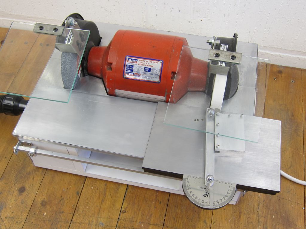
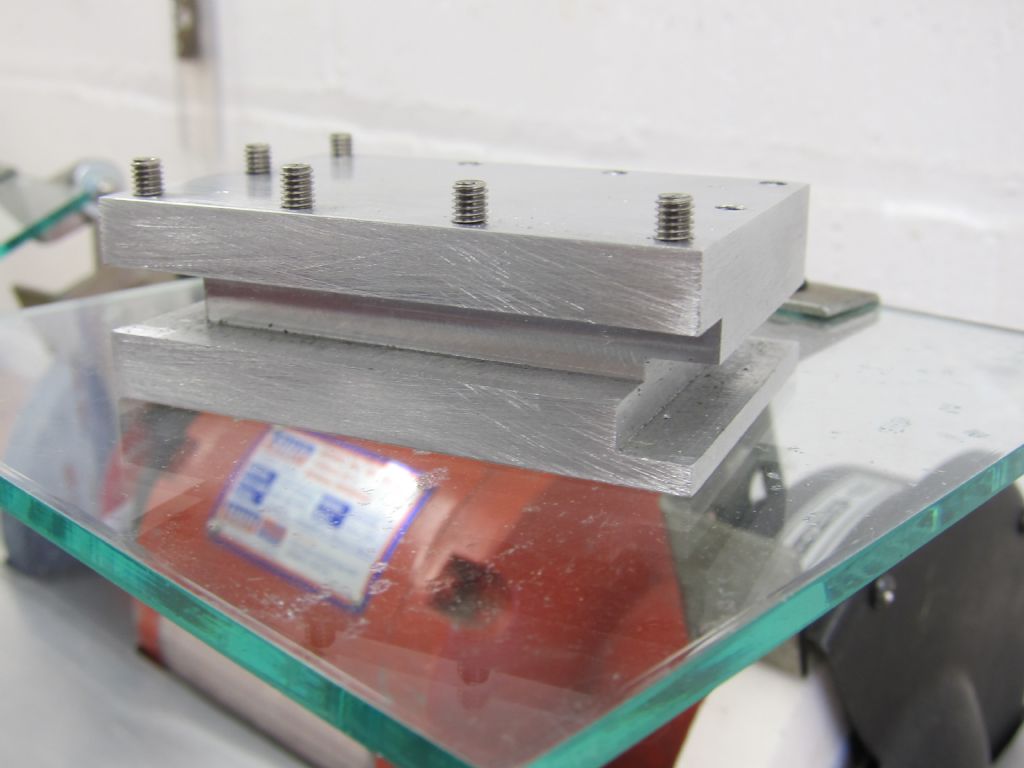
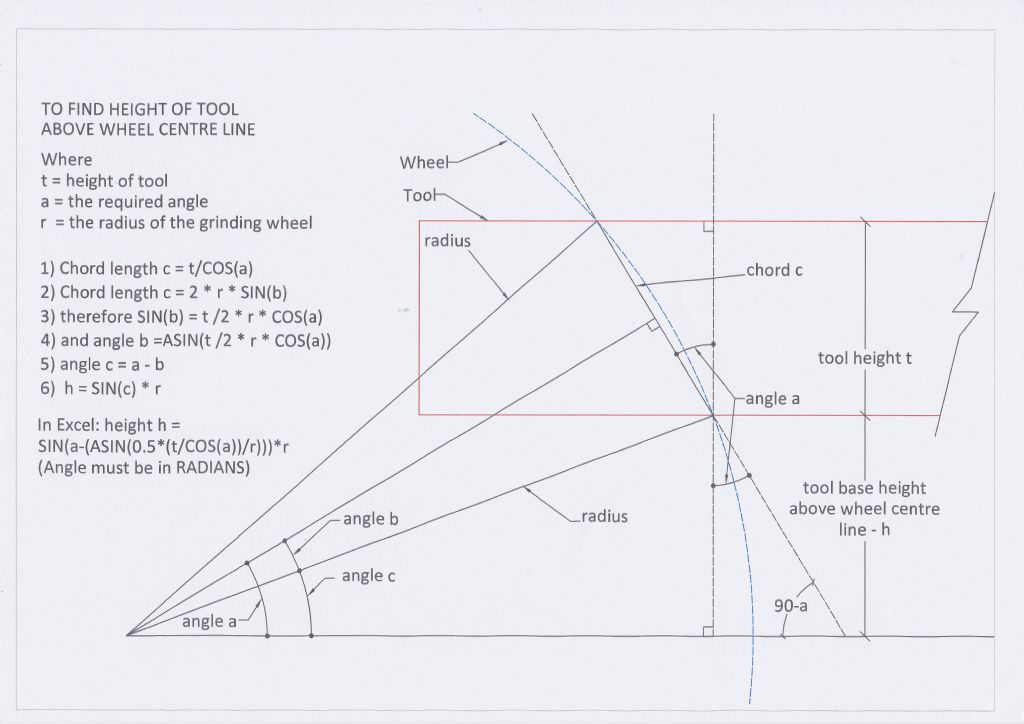
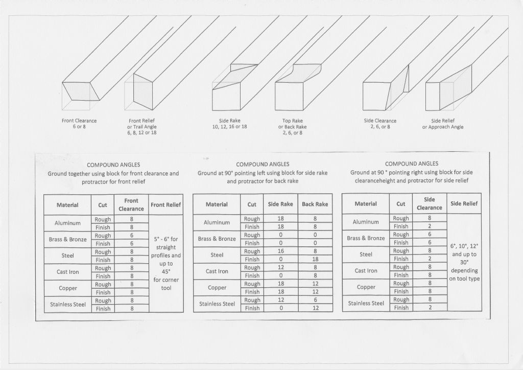
                          I have completed my version of the tool grinding rest. The wheels are partly enclosed and the casing has extraction holes which work well in reducing the dust spread. The casing top and sliding part are made from plywood bonded to 0.5mm steel sheet (from B&Q!), the protractor is a cheap one from eBay and there are holes at commonly used angles with a tapered pin to lock the arm, this makes for easy repeatability. If you vary from Graham Sadler's design you need to re-calculate the tool height relative to the wheel centre line, the geometry is shown on the drawing image and if you use Microsoft Excel the expression for the height of the bottom of the tool above wheel centre is: SIN(a-(ASIN(0.5*(t/COS(a))/r)))*r where a is angle required, t is the height of your tool and r the radius of the wheel. I also prepared a sheet which simplifies the various types of angles on the tool. Finally I made tool holders to give front clearance angles of 2°, 6° and 8°, these are simply machined from aluminium and have slots at 90° for grinding side rakes etc. Photos and drawings attached.

                          Grinding Rest 1Grinding Rest 2Grinding Rest 4Geometrytool angles.jpg

                          Edited By Chris Taylor 3 on 28/01/2019 11:41:23

                        Viewing 11 posts - 1 through 11 (of 11 total)
                        • Please log in to reply to this topic. Registering is free and easy using the links on the menu at the top of this page.

                        Advert

                        Latest Replies

                        Viewing 25 topics - 1 through 25 (of 25 total)
                        Viewing 25 topics - 1 through 25 (of 25 total)

                        View full reply list.

                        Advert

                        Newsletter Sign-up