What Did You Do Today 2020

Advert

What Did You Do Today 2020

Home Forums The Tea Room What Did You Do Today 2020

Viewing 25 posts - 576 through 600 (of 636 total)
  • Author
    Posts
  • #501597
    Dullnote
    Participant
      @dullnote

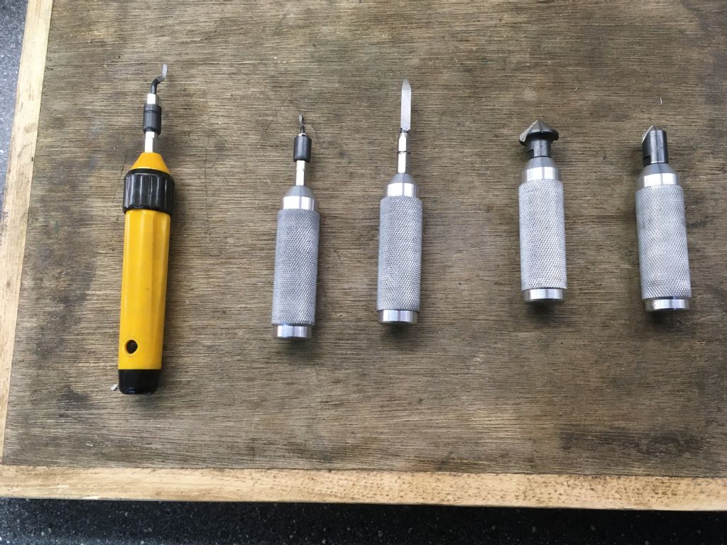
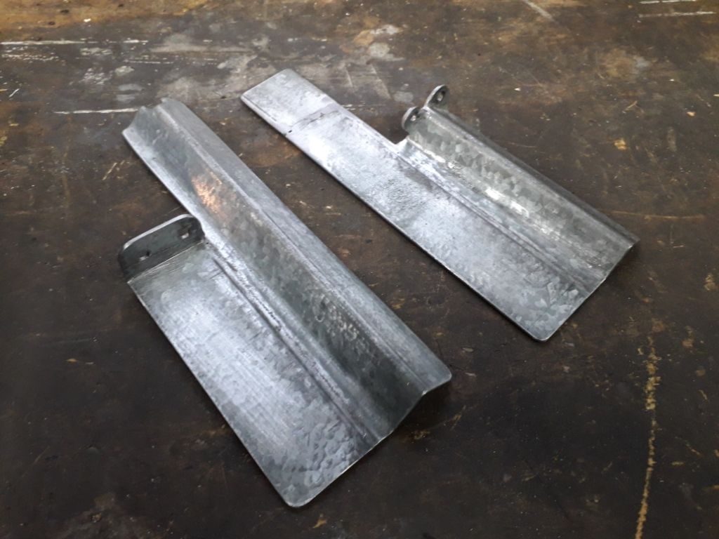
      just got fed up change blades in holders, so made up some new ones out of alum bar

      Advert
      #501598
      Dullnote
      Participant
        @dullnote

        4d9a9779-7174-40a2-bb50-6e2daac1d115.jpeg

        #501782
        Nigel Graham 2
        Participant
          @nigelgraham2

          Good idea, Dullnote!

          ===

          Today – well as most of the week really.

          Continued building a special bench to hold my small flypress, a bench vice and other sundries. These include the option to mount the Drummond manual shaper on it; all held by screws tapped into the two-foot square of 10mm stell plate forming its upper surface so they can be readily changed around to suit. This does mean the bench has to be robust and secured to the floor and walls, which are concrete, as using the press and even more the shaper, would put a heavy lateral stresses on it additionally to the machines' dead-weights.

          I had set off with the best of intentions using wood salvaged from old pallets – free, broken ones put out for collection as firewood by a pallet-supplier whose yard I pass fairly regularly.

          All good intentions but eventually I realised that the amount of cutting, altering, fettling and faffing, and the vast numbers of screws it was using, made this a remarkably time-wasting approach compared to using spare, new or second-hand but good-quality timber I already had in stock but saving for best!

          Such wood-work would work with wood-work equipment such as a planer/thicknesser to trim the disparate laths to consistent thickness and widths. It's a lot harder with only hand saws and planes.

          Broke one of my planes, too. A proper Stanley one with a rather thin cast-iron body, it snapped in two while I was re-setting the blade. Inspection showed signs of an old, fine crack. I suppose we've had our money's worth out of it as I think it had been my Dad's, possibly even Grandad's,. Anyway, I expect it's out of guarantee.

          So I have started again…

          +++

          Alibre don't give up, do they?

          It must be a year since I abandoned the MEW offer and stuck with the TurboCAD I already owned, fully paid for and a lot cheaper; and closed my Alibre "account" before they could start charging me for it. Yet I have just received out of the blue, and deleted, a fancy e-mail from Alibre waffling about the latest things they've added or corrected in their software.

          Surely if they had not heard from me all that time, and no longer had an Alibre "account", you'd think they'd realise that's because I had stopped using their CAD software. Oh well, that's the software trade for you, I suppose.

          #502437
          John Hinkley
          Participant
            @johnhinkley26699

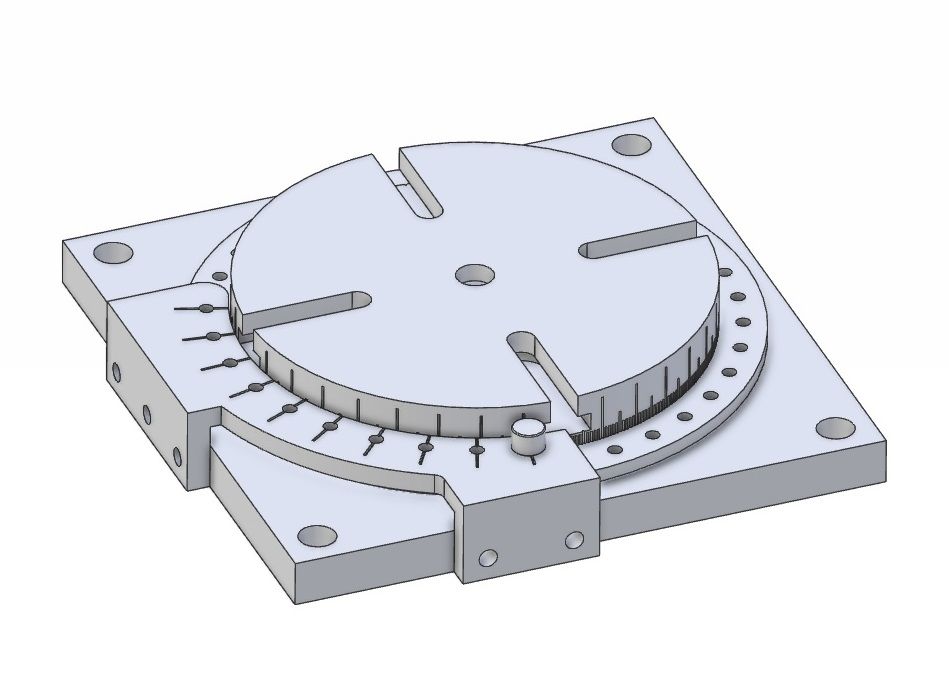
            Been at a bit of a loose end these last few days so I spent some time at the computer thinking up another piece of workshop tooling. This is a low-profile rotary table with a one degree rotational restraint system based on the simple indexer tool described in my album and in MEW 297/298. Here's a screengrab of the work so far. For scale, the height from bottom of the base to top of the table is 26mm, the table itself is 100mm diameter and the base is 130mm square, tee slots are just 6mm wide, so it's aimed at mini-mill users. There are a couple of refinements to add – like a table locking device and adding fasteners etc. I originally intended to add a simple form of adjustable jaws to fit in the tee slots but decided that, at least for the time being, I'd stick with clamps. It is only designed for use with very small components after all. You never know, I may even get around to making one now that we are going into COVID tier 3 on Saturday.

            Vernier table

            John

            P.S. All the best to Muzzer in Oz from me, too.

            Edited By John Hinkley on 21/10/2020 11:04:42

            #502733
            John Hinkley
            Participant
              @johnhinkley26699

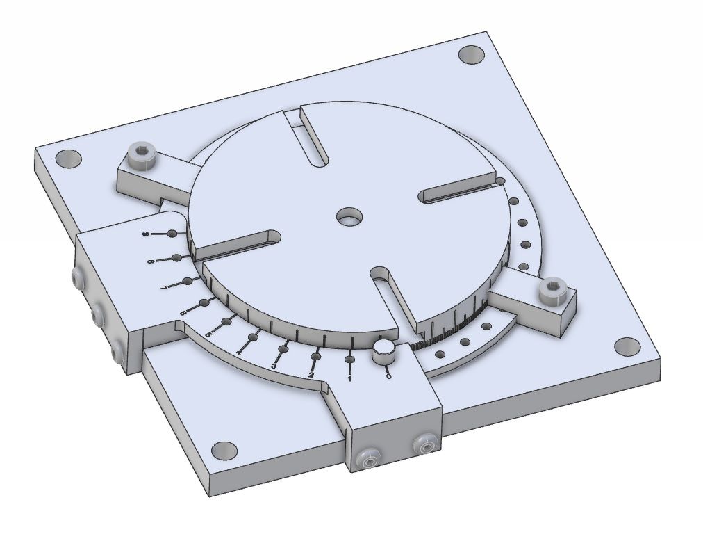
              Loose ends tied up, so finished the rotab design:

              Completed design

              The base ended up 130mm square to accommodate the locking clamps , otherwise it's substantially as it looked in my head. All designed 'on the fly' in Alibre Atom3D. Time to break out the metal catalogue!

              John

              #502735
              Steviegtr
              Participant
                @steviegtr
                Posted by John Hinkley on 22/10/2020 14:58:22:

                Loose ends tied up, so finished the rotab design:

                Completed design

                The base ended up 130mm square to accommodate the locking clamps , otherwise it's substantially as it looked in my head. All designed 'on the fly' in Alibre Atom3D. Time to break out the metal catalogue!

                John

                It would be good to see that when finished. yes

                Steve.

                #502742
                John Haine
                Participant
                  @johnhaine32865
                  Posted by Nigel Graham 2 on 16/10/2020 19:59:29:

                  Surely if they had not heard from me all that time, and no longer had an Alibre "account", you'd think they'd realise that's because I had stopped using their CAD software. Oh well, that's the software trade for you, I suppose.

                  Doesn't cost them a penny to email you and you might have changed your mind!

                  #502777
                  Nigel Graham 2
                  Participant
                    @nigelgraham2

                    You could be right, John!

                    I am pretty sure I told Alibre's publishers I was closing my account, and I had taken out no software subscription with it, which is why I was surprised it sent me an unsolicited e-mail over a year later.

                    '

                    I was really struggling with TurboCAD and when MEW presented the Alibre offer I thought I would try it – a fresh start with proper instructions. I have subscribed to ME for years, and still do, but not MEW. So I had to buy the first instalment's magazine in WH Smiths.

                    I read the article carefully, loaded Alibre and followed the instructions. Fairly soon, I had a nice scribing-block base on the screen, took up the suggestion to experiment so enlarged its diameter and recessed the base similarly to my real one, to make it more stable. Wow!

                    Then things went to pot! I bought an MEW subscription, but must have entered the wrong edition on the form, and lost the next two instalments. Thrown, then learning I would eventually have to subscribe to this new software when I had made some progress with the TurboCAD I had bought and paid-for, I realised I was far better staying with TC. So have.

                    I'd had inklings of what CAD can do, not directly but from the engineering-drawings I had seen at work and provided with the Hemingway kits, so I knew its advantages even if you only ever make orthogonal drawings . I regard isometric drawing's main value is in designing assemblies, and rendered pictures are for brochures; but extremely difficult to learn.

                    TurboCAD was also advertised regularly in our magazines, and Paul Tracey had his TC sales stands at the exhibitions, where indeed I bought my copy. It has also has the advantage of allowing direct orthographic drawings for workshop use, rather than the long and hard 3D-model way round. (I am not sure if you can even take elevations off a 3D drawing in TurboCAD.)

                    '

                    So Alibre took its place with Fusion 360 – tried but not for me, though Fusion is or was free for hobby users. I have a copy of AutoCAD 2000 but with no manuals available, made no progress with it.

                    I did investigate Solid-xxxx, which was my employers' choice and I think taken up by one or two fellow club-members. It was certainly taught at by one at school-level, so I could have found local help; but its web-site implied it was unavailable to private buyers – or very expensive if it was.

                    I'd also tried a few "free" other CAD programmes available on-line, but most were very limited and no use for mechanical-engineering. One did cater for engineering, and looked promising until I found some of its most useful tools were switched off – a trial or student version.

                    #503653
                    Anonymous

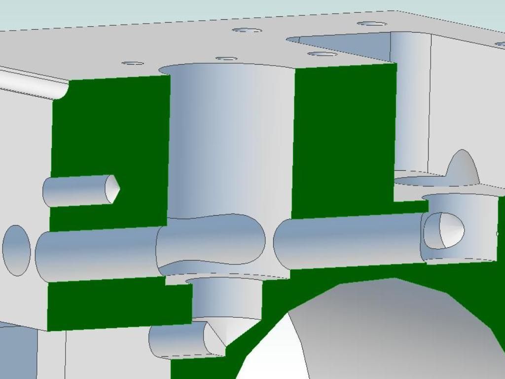
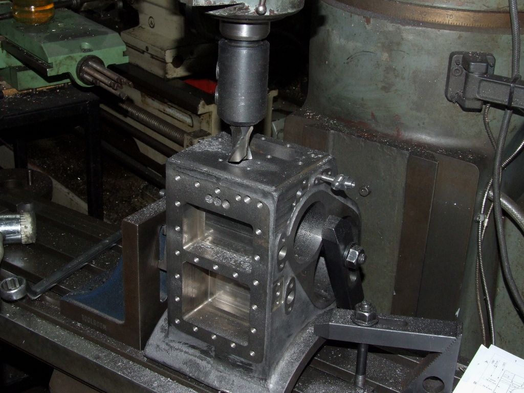
                      Over the last couple of nights I've been machining the hole for the balanced valve and body, and one of the steam passages into the HP valve chest, for the governor on my cylinder blocks. The result isn't easy to photograph and it's just a hole! So a section of my 3D CAD model of the cylinder might be more informative:

                      cylinder block - governor section.jpg

                      It's not a disaster if the hole breaks into the HP cylinder bore as a thick liner will be fitted. But it's a case of satisfaction if it doesn't. The large 1" hole was machined with a slot drill, usaing the knee rather than the quill to set the precise depth:

                      governot hole.jpg

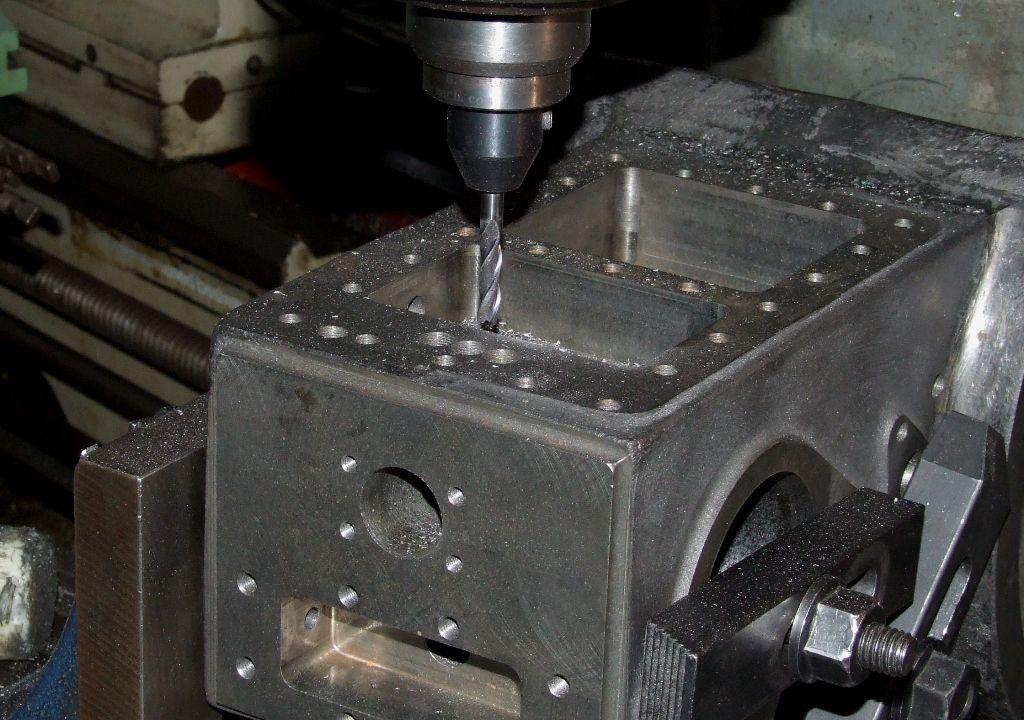
                      The oblong slot from the bottom of the balanced valve to the HP valve chest was drilled 6mm at each end. The middle was then "drilled" using a 6mm slot drill with a fair amount of stick out:

                      governor slot.jpg

                      Finally the slot was cleaned up by machining from side to side with a step down of 1mm. Machining the slot is not as bad as it looks. The first 1" is fresh air and once engaged the cutter is contrained on two sides.

                      Eventually there will be two drilled passages from the HP valve chest to the top of the balanced valve, but they will be done after the valve body is finally fitted.

                      Andrew

                      #503797
                      Iain Downs
                      Participant
                        @iaindowns78295

                        I've been a bit quiet the least few weeks as a bathroom refurbishment interrupted play. AS usual with these things, you peel a layer back and find more problems and so it goes.

                        However, in the background I've been making a saddle clamp for my mini lathe. This, in some ways was an act of desperation. Desperation for parting off (a common whine!).

                        Some considerable time back, I got a decent QCTP from Arc and the first few partings off of steel went really well (by my standards). Not much digging in, swarf not dust coming off and I was delighted.

                        However, either over time or at some point, this all seemed to stop working. parting off, grooving, treppaning could only be done with the utmost delicacy or very nasty things happened.

                        One of the you tubes I watched recently talked about saddle clamps, so I thought I'd have a go. I'd already made a topslide clamp which had no effect on the parting off at all.

                        As part of the process, I had a look at the saddle and put an indicator on it there was well over a thou of movement up and down, which I thought was a bit much. I then nipped up the nuts which grip the saddle to the underside of the bed and got to the point where the movement was something like 8 microns. I had to stop that that point (as if I could do better) as, although the movement was smooth towards the chuck, in the last part towards the tailstock it was very stiff. I'm assuming that there is just a bit of wear in the area where I've been cutting.

                        Anyway I found that interesting.

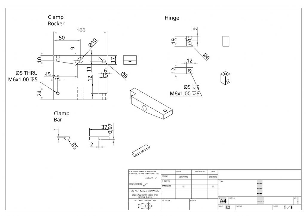
                        Here's a drawing of the clamp.

                        saddleclamp drawing.jpg

                        The hinge is bolted under the front of the saddle and a 6mm pin (not shown) hinges the Clamp rocker. Half way along a half round bar sticks through and when the screw at the back of the saddle is tightened it brings it up to clamp under the ways. The idea is to ensure the clamping force is central rather than at the rear end only which I've seen on some designs.

                        I actually only trimmed the ends of the Clamp Bar, which gave a better bearing for the bar and also prevented the bar from wandering out of the Clamp Rocker.

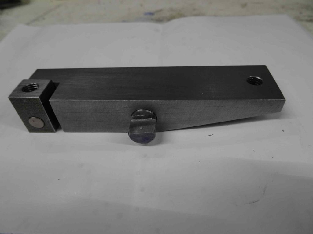
                        Here's the part

                        saddleclamp 01.jpg

                        And here it is on the saddle with the clamp off

                        saddleclamp off.jpg

                        and less than a quarter turn later, no.

                        saddleclamp on.jpg

                        The socket head bolts at the front and back are counterbored to keep out of the way of the saddle mechanism (in the above image specifically the jib screws).

                        I did some sums and thought that I only needed a few thou to accommodate the forward and back movement of the clamp rocker as it raised and lowered. However, between possibly bad maths and imprecise location, I ended up with this end overbored (6.5 rather than 6 and 11.5 rather than 10.5 for the counterbore) to accommodate some movement.

                        I've not yet tried it out. I wanted to quite whilst I was ahead tonight. Also I will never know if the improvement was due to tightening the saddle or the clamp – though I suppose I could try without it first..

                        Iain

                        #503798
                        Robin
                        Participant
                          @robin

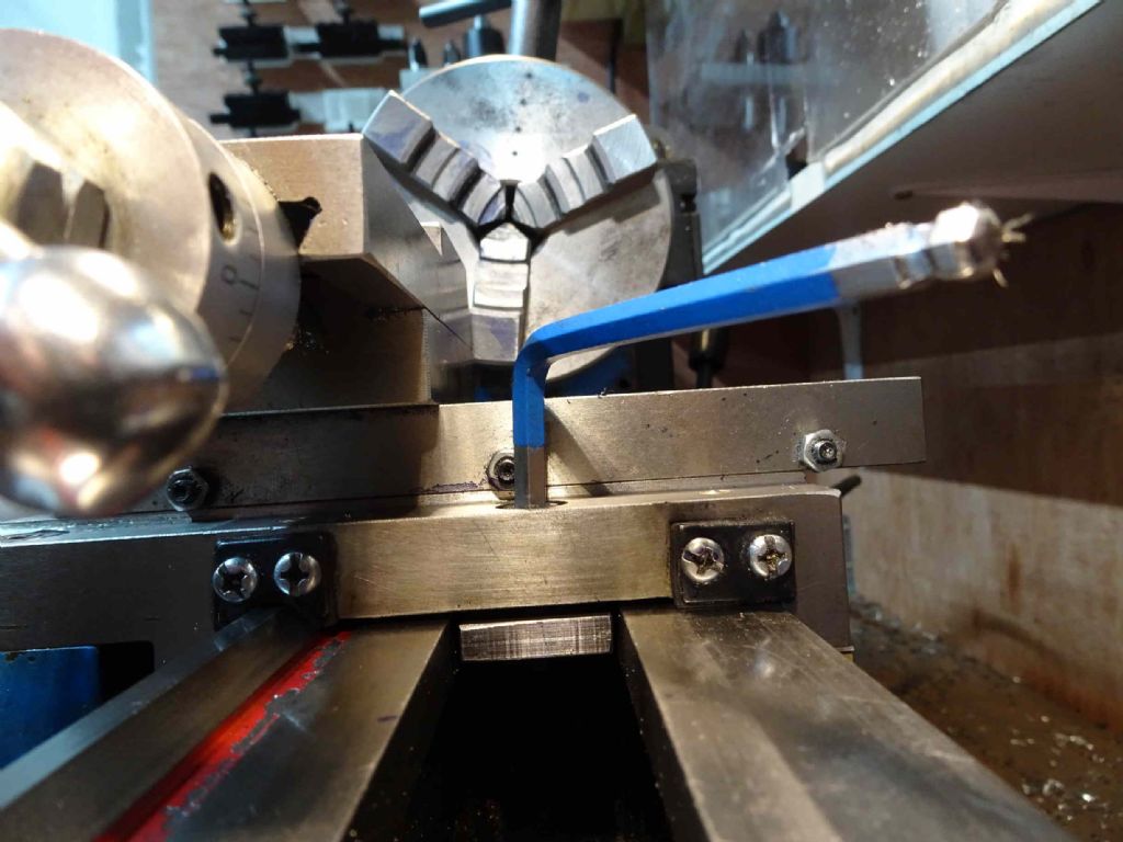
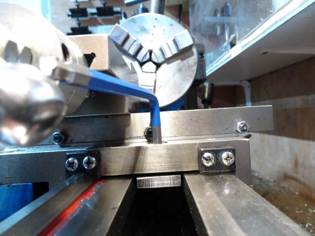
                          Thought I might tackle the 4 degrees of slop on the surface grinder X-axis handle.

                          I quickly diagnosed too much gap between rack and pinion so I raised the rack by a tentative British Standard lolly stick (2mm).

                          The slop reduced but the table developed a clunk at the far left end of its travel.

                          I then diagnosed insufficient counterbore depth. Meaning the pinion is hitting the head of an Allen screw, the one with the key sticking out the top in the picture.

                          I am not complaining, with a bit of effort, I will get a much nicer machine than I actually paid for. It is all there, I just need to reveal it smiley

                          #504797
                          Anonymous

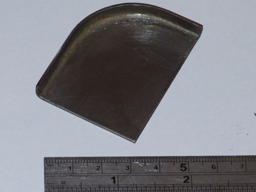
                            On the drawings for my traction engines there is nothing detailed for oil feeds to the 2nd and rear axle shaft tubes. The pictures I have of full size engines are all different. I've been designing a setup based on an amalgam of the full size pictures. On the right hand side both oilers will be mounted on a flanged tray, also used to hold other items such as oil cans. The tray has been designed as a sheet metal part using 1mm thick steel sheet.

                            As some members will be aware I've made the spectacle and front plates for my engines by hot forming 3mm steel sheet over a former. Conveniently I chose to use the same curve radius on the oiler tray. One of the lessons I learnt when forming the 3mm sheet was that if the metal kinked when forming the curve it was game over. I thought that the 1mm sheet may be more prone to kinking.

                            This morning I did a trial forming on an offcut of 1mm sheet. It went much better than expected and took about 10 minutes. The heating with the oxy-acetylene set was very quick:

                            oiler_tray_trial.jpg

                            Before doing the proper parts I'll make a smaller wooden mallet as it will give more control.

                            Andrew

                            #504805
                            Bazyle
                            Participant
                              @bazyle

                              Belatedly I have looked moe closely at Ian's clamp above and eventually understood how it fits. Rather neat so myight look at how it could work on a Drummond. Thanks for the posting.

                              #504885
                              mechman48
                              Participant
                                @mechman48

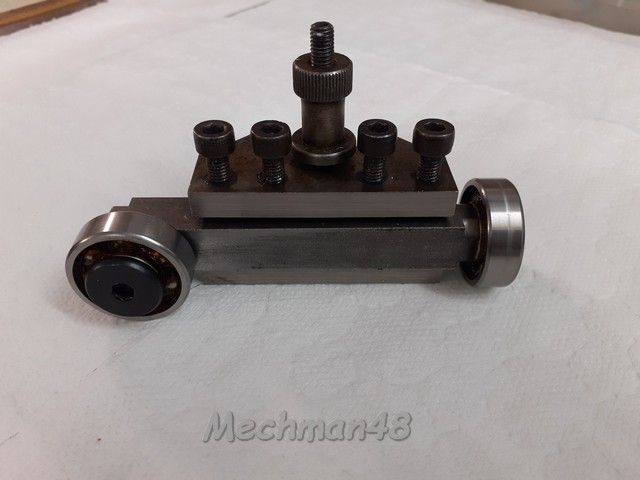
                                Yesterday actually; was getting on with my beam engine but it was one of 'those days' nowt was going right so put it back on the back burner,instead decided to modify my home made 'pusher tool', put one bearing at 90* to other..

                                Pusher tool.jpg

                                George.

                                #505202
                                Colin Heseltine
                                Participant
                                  @colinheseltine48622

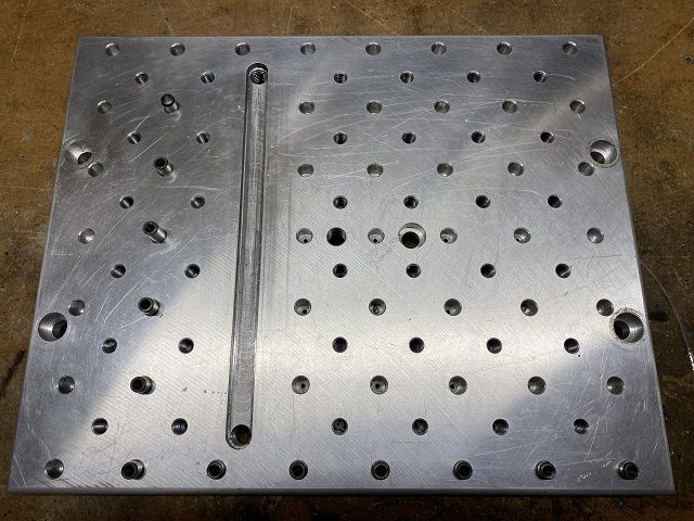
                                  In another post I asked questions regarding reaming holes for a fixture plate. Well the plate is now finished with 50 plus 10mm reamed holes and around 40 M10 tapped holes.

                                  fixtureplatefinishres.jpg

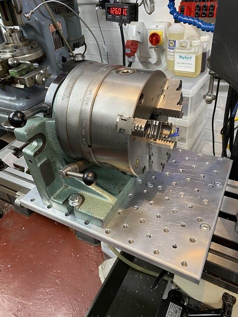
                                  The fixture plate is dual purpose as its main intention is as a mounting plate for my Bison 8" indexer.

                                  This evening I finished the last slot in the fixture plate and made the final tenon for the indexer.

                                  Amazingly it fitted together, albeit after I had to correct a slight miscalculation I had made on the length of the slot for the last tenon..

                                  mountedindexerres.jpg

                                  Need to use it for something now.

                                  Colin

                                  #505363
                                  Nigel Graham 2
                                  Participant
                                    @nigelgraham2

                                    Wow! My workshop now has a good-sized bench-vice fitted to a bench at last!

                                    I built a small but heavy-duty bench with a 10mm thick steel plate nearly two feet square screwed to the top, drilled and tapped to take the vice and variously a small fly-press, Drummond manual shaper and rotary shear, moveable for use or storage as needed. It will also be suitable for holding the WNS jenny.

                                    The shaper already lives on another bench and might stay there, but I took the opportunity to give the option of moving it.

                                    Celebrated by using the vice to cut some wood to make a shelf for the trolley I built for an Alpine-badged clone band-saw. I removed the saw-stand's awful, original two wheels and handle and nested the stand in a welded angle-iron trolley with hefty castors, to move it easily around the cramped workshop. Some quick "carpentry" soon formed a useful tool-box placement, using cut-down pallet-slats screwed to garden trellis-batten cross-members laying within the trolley frame, .

                                    Finished this afternoon by commencing re-commissioning the Denbigh H4 horizontal mill. All that effort I put into making a travelling-hoist is paying off. I had used it for manipulating that bench-top and the fly-press; and now could lift the knee off the mill then the machine body off its cast-iron stand, fairly easily and more importantly, safely; using a Clarke chain-hoist and proper slings.

                                    The bench-plate, incidentally, has 4 tapped holes for lifting-lugs / eye-bolts.

                                    #505365
                                    Steviegtr
                                    Participant
                                      @steviegtr

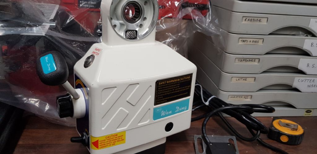
                                      This arrived today so lots of bushings to make / alter to make it fit. It is a x axis drive for a Bridgeport. Going on the little Tom Senior as a Z drive.

                                      Steve.

                                      new z axis motor.jpg

                                      #506327
                                      Nigel Graham 2
                                      Participant
                                        @nigelgraham2

                                        Today, I….

                                        … Continued rebuilding my Denbigh H-something horizontal mill. In theory it is a model H4 Auto, the word meaning powered long feed by the usual wheel and worm driven via the usual telescopic, jointed shaft, from a small pulley and belt set on the back of the machine.

                                        This example came from a bereavement sale. Its previous owner, a vehicle restorer, had left a steel shed full of remarkably rusty machine tools on a floor of earth and straw. So it was in a bit of a state, but serviceable after a fashion, driven by a confection of ancient single-phase motor, old 3-speed Ford car gearbox and motorcycle chain to a sprocket screwed to the original flat-belt pulley on the spindle.

                                        It lacked all trace of the "auto" though, apart from a small embossed facing on the rear of the machine body, and the worm-wheel.

                                        I identified the mill eventually thanks to Tony Griffiths, and last night returned to his lathes site to investigate further, with a view to re-worming the machine.

                                        Mr. Griffiths remarks that some of Denbigh's milling-machines, intended as lower-cost for educational establishments and the like, lacked quality fits and finishes.

                                        He's right there:

                                        I wire-brushed the tatty paint-work back to bare metal and discovered that short of spending a lot of time and money on filler and sandpaper, no amount of painting will hide the roughness of the castings. Still, all my machine-tools are very much pre-loved and look it, and I can accept presentable rather than exhibition finish on an old machine-tool intended for using not admiring.

                                        More annoying though, the 6 screw-holes in the threaded steel bush that is the knee-screw nut, were so out of angular pitch that despite their being well over their nominal 2BA clearance diameters, it took me several iterations to find the right rotational match for the part.

                                        The research showed something odd though. Of the Denbigh H-series, only the H4 Auto had a longitudinal lead-screw, thanks to being an "Auto". The others had lever-action, manual feeds. I had assumed mine had simply lost its power-feed bits apart from the worm-wheel, over the years; but the lathes.co pictures clearly show the table on my machine also lacks its T-slot for the feed knock-off block.

                                        Strange. I will examine the table to see if like its companion parts it bears a stamped number 4 I assume is the model, not a batch, number. I have found no serial number either, nor signs of any lost number-plate. I wonder if the power-feed was an option that could be retro-fitted, using the tapped holes already there in the cross-slide and the facing on the back of the column, but why the "wrong" table? The table is for a screw-feed model as it has no features possibly associated with a lever-feed, but a plain underside, arched to clear the feed nut and worm bearing housings integral with the cross-slide. Yet has no slot for the travel-limiter.

                                        I would like to fit it with power-feed in keeping, but am not sure how to identify a worm matching the wheel (12DP? Approx 1.8" pcd, 22T). An orphaned worm I have, seems to fit but with a 2-start thread, it lies at an angle to the wheel, adding to the fun.

                                        #506575
                                        peak4
                                        Participant
                                          @peak4

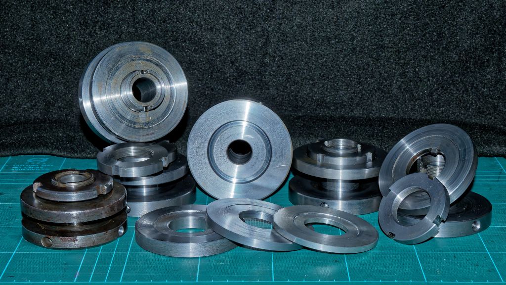
                                          Finally got round to completing another 5 arbors to hold pre-balanced grinding wheels for the Herbert.
                                          All essentially copies of the original at lower left.
                                          Four with 1 ¼" (31.75mm) cores and one with 32mm to suit a diamond wheel I have.
                                          22tpi Left Hand thread on the 2" slotted nuts, screwcut in the lathe. The main body is a shade over 3" diameter.
                                          I should work faster, they're already starting to show signs of rust before I've even mounted any wheels.

                                          pb10269Herbert Junior Wheel Arbors

                                          Bill

                                          Edited By peak4 on 10/11/2020 20:46:21

                                          #506879
                                          Iain Downs
                                          Participant
                                            @iaindowns78295

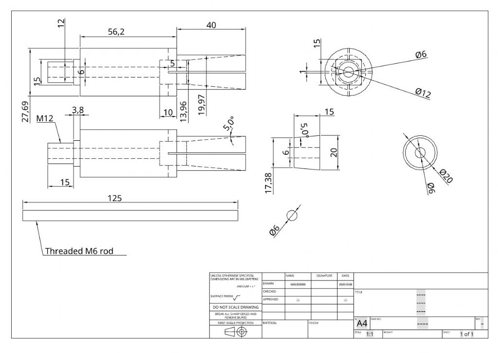
                                            A while ago I had a go at building a spindle handle / mandrel based in some ideas in Neil's excellent book.

                                            It was a failure (I blame the workman, by the way Mr Editor, not the writer!).

                                            So I thought I'd have another go. This was the basic idea. I think that the first attempt may have failed because the angle of the plug was too steep (and the machining probably too rough).

                                            spindlehandleplans.jpg

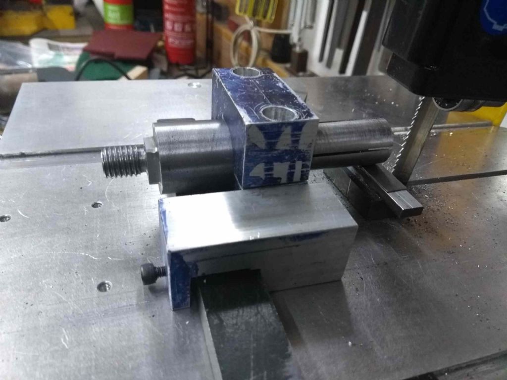
                                            The main challenge with this was cutting the slots and the square on the other end.

                                            To accomplish this, I build a little block which I could clamp the bar in and then set it up on my saw table (and later the mill). the picture below is entirely posed because I didn't have a camera when I did the real work.

                                            spindlehandle2making.jpg

                                            The scrap just in front of the blade are some bits superglued together to provide some support for the work – or it would go all over the place!.

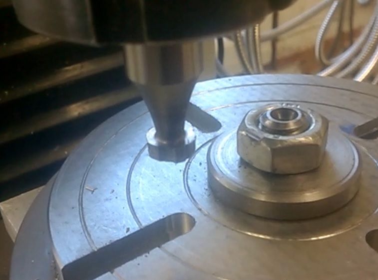
                                            Here's the finished product

                                            spindlehandle2made.jpg

                                            I've established that it fits in the spindle and I can get it locked up reasonably well with only finger pressure. Not yet used it in anger.

                                            However, that's not quite the end of the story (he digresses).

                                            As a beginner, parting off was a bit of a trial. In fact a disaster. Until I bought a decent Quick Change tool post from ARC with a parting tool holder. This went really well, even on steel.

                                            For a while. I don't know quite when but it stopped working nicely and the last year or so parting off has been a truly delicate operation with a nasty combination of grazing dust off and horrid horrid dig ins which felt like the lathe was about to burst.

                                            So for the puller (part triangle, God knows what to call it) with the angle at the end. Arghh! Cried I and pulled out a bit of HSS I'd ground a less than 1mm wide parting bit into ages ago.

                                            all of a sudden, I could part off. The steel came twirling off like it was dancing! I grooved the part to make space of the taper and then parted through. It was lovely!

                                            Since then I've bought a indexable parting tool (usual source!) and that works brilliantly!

                                            I have no idea what specifically I have been doing wrong, but the obvious culprit is the parting blade which I have ground down myself (and reground and sharpened).

                                            So I'm actually happier that I seem to be able to part again than that I've made a nice handle!

                                            Iain

                                            #507454
                                            John Hinkley
                                            Participant
                                              @johnhinkley26699

                                              What happened yesterday, actually, but it's taken me 24 hours to decide whether to share my stupidity or not. Oh well, in for a penny and all that ……

                                              Look Mum, No teeth!

                                              Toothless cutter

                                              Once upon a time there was a Woodruff key cutter. One day, its owner decided he could make it cut just a little bit further. The cutter thought otherwise and spat out all its teeth. "Oh, Golly, Gosh", said the twit driving it, "I'll learn from that!

                                              And I did.. To the tune of twenty-eight quid for two new ones (one spare, 'cos I'm bound to do it again.)

                                              Luckily, I didn't capture it on video for the build series, but I'll try to when the replacements come.

                                              Consoled myself with drilling the 36 holes at 10° intervals in the flange.

                                              Link to latest video

                                              John

                                              #507468
                                              Nigel McBurney 1
                                              Participant
                                                @nigelmcburney1

                                                I have a Colchester master and a S7, a while back I did not use the master for a couple of weeks,when next went to use it the motor was making a loud grumbling sound, my thought was motor bearing on way out. Naughty but I did continue to use it for odd jobs and put up with noise,or used the Myford. then the Myford motor started to rattle,a check round revealed the motor pulley was loose, easily rectified ,the Colchester was left until today,not looking forward to working on the Master as anything in the base is a pig to get at,ok if in a factory,but in the shed up against the wall makes things difficult,removed belts ,run motor ,still noisy,so its motor problem,so after the Myford problem I checked the pulley which is secured by decent sized key and skt head grub screw,its a 5hp motor, screw was stiff so had to be turned with some effort ,only to find the screw could be turned about 5 turns,Tightened and noise problem cured,hooray easy solution for a change, I bought the lathe direct at an ex goverment sale so somebody must have worked on the motor and forgot to tighten it ,I have owned the lathe for a dozen years,one earlier problem was the fan at the other end of the motor came loose which was an utter pig to get at, so why did they decide to come loose after years of running,one thought was ,does running on a static converter cause unusual vibrations , and its strange that the Myford pulley also came loose within a few weeks of the Colchester.both machines around 40 years old.

                                                #507550
                                                Nigel Graham 2
                                                Participant
                                                  @nigelgraham2

                                                  Well, I have re-assembled my Denbigh H4 "Auto" Horizontal Mill, screwed to the concrete floor with those big self-tapping screws for concrete.

                                                  The machine is now waiting for a second coat of paint – humidity and cool air mean paint takes longer to dry.

                                                  Meanwhile, how to drive it. I spent yesterday evening using an Excel spread-sheet to calculate suitable combinations of my stock of pulleys and two hefty great Mod.3 gear pairs "in stock", to match a near-1400 rpm motor to around 40rpm and 100 rpm spindle speeds.

                                                  That lower is based on a 4" dia cutter on mild-steel, guided by text-books of appropriate age, to give a cutting-speed in the recommended range. 100rpm would be for brass and aluminium – the book rates are higher for them, but at production rates.

                                                  Then about two hours this afternoon staring at the mill, the wall behind it, the motor, the wheels standing in appropriate "ghost" positions in the table T-slots…. to no avail!

                                                  I find this now and again; running out of inspiration. it's not helped by the mill, parallel to the Myford vertical mill, being at an angle to the workshop wall for space-saving. The illusion gives the impression of the resulting layout difficulties being worse than reality.

                                                  So… Maybe time to add the second coat of gloss mid-grey and turn to another project for a while….

                                                  Perhaps the replacement over-arm drop-bracket will take my mind off gear-boxes and long V-belt runs, although I would not be able to finish-machine it until I have installed all that transmission! (By boring the bearing hole from the spindle itself, with the bracket clamped to an angle-plate on the table, and the over-arm set to slide smoothly with the in-feed.)

                                                  When I bought the machine its drop-bracket was a casting of unknown origin, and was broken. The drive was a rough-and-ready confection of motor, antique car gear-box and chain-drive on an angle-iron frame above the machine.

                                                  #507551
                                                  Steviegtr
                                                  Participant
                                                    @steviegtr

                                                    Nothing engineering. Fitted & wired a Nest learning thermostat to the heating system.

                                                    Steve.

                                                    #508031
                                                    Henry Brown
                                                    Participant
                                                      @henrybrown95529

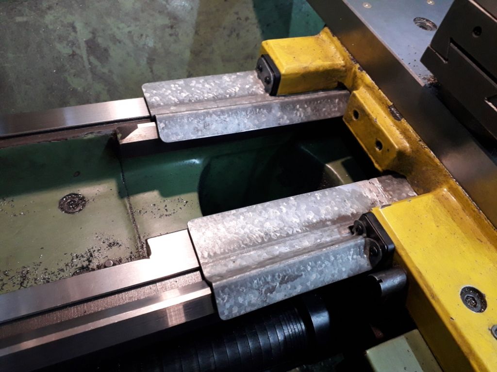
                                                      I've been going to make some slide covers for a while, the original plan was to machine them from ali but I came across some up and over door runners and harvested enough 2mm thick lengths to make these…

                                                      slide covers 1.jpg

                                                      I quite enjoy a bit of tin bashing on occasion and these went quite well, I fitted them on top of the existing slide wipers and they looked like this:

                                                      slide covers 2.jpg

                                                      I need something to stick along the edge end, I'll experiment with some rubber or a length of split tube to finish them off.

                                                    Viewing 25 posts - 576 through 600 (of 636 total)
                                                    • Please log in to reply to this topic. Registering is free and easy using the links on the menu at the top of this page.

                                                    Advert

                                                    Latest Replies

                                                    Home Forums The Tea Room Topics

                                                    Viewing 25 topics - 1 through 25 (of 25 total)
                                                    Viewing 25 topics - 1 through 25 (of 25 total)

                                                    View full reply list.

                                                    Advert

                                                    Newsletter Sign-up