Warco WM250

Advert

Warco WM250

Viewing 25 posts - 201 through 225 (of 245 total)
  • Author
    Posts
  • #291061
    Dusty
    Participant
      @dusty

      It has taken a while to get everything connected, after some minor mods to the lathe while it's in bits. I now have a lathe that runs and the spindle turns. I connected the 'filter' into the circuit as this powers the speed readout. The filter as I understand it changes AC into DC well it did in the original power set up. It does not work. Do I need to complete the circuit on the output side to make it work? I would like to get this part sorted out before going on to programme the pot.

      Advert
      #291074
      Les Jones 1
      Participant
        @lesjones1

        Have you remembered to connect the display and speed sensor to the filter board ?

        Les.

        #291075
        Dusty
        Participant
          @dusty

          Les, Yes all connected.

          #291079
          Les Jones 1
          Participant
            @lesjones1

            Is the display totaly dead or does it just read zero ?

            Les.

            #291085
            Dusty
            Participant
              @dusty

              Dead, totally lifeless.

              #291087
              John Rudd
              Participant
                @johnrudd16576

                Dusty,

                The filter board as you put it, is also the power supply for the speed readout, but I guess you figured that bit out…

                I'll have a look at how I wired mine and get back to you with a picture or a scheme on how to connect it….

                Can you post up a picture of your filter board? Just in case yours is different to mine…( I doubt it but you never know…)

                #291088
                Les Jones 1
                Participant
                  @lesjones1

                  Do you have 230 volts between the L and N input terminals of the filter board ? If you do have power to the filter board you will need to trace out the schematic of the board. I think there will only be a transformer, a bridge rectifier a smoothing capacitor an possibly a voltage regulator. (Plus the filter components for the mains.)

                  Les.

                  #291107
                  John Rudd
                  Participant
                    @johnrudd16576

                    Dusty,

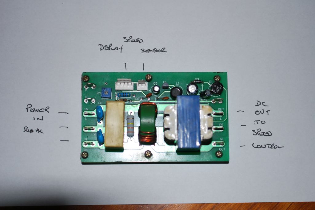
                    Had a look my board….at one end there are 4 spades connectors adjacent to the transformer, I took the feed to my inverter from the L and N from there….. At the far end there are two spades where the mains comes in….

                    How have you wired yours?

                    #291209
                    Dusty
                    Participant
                      @dusty

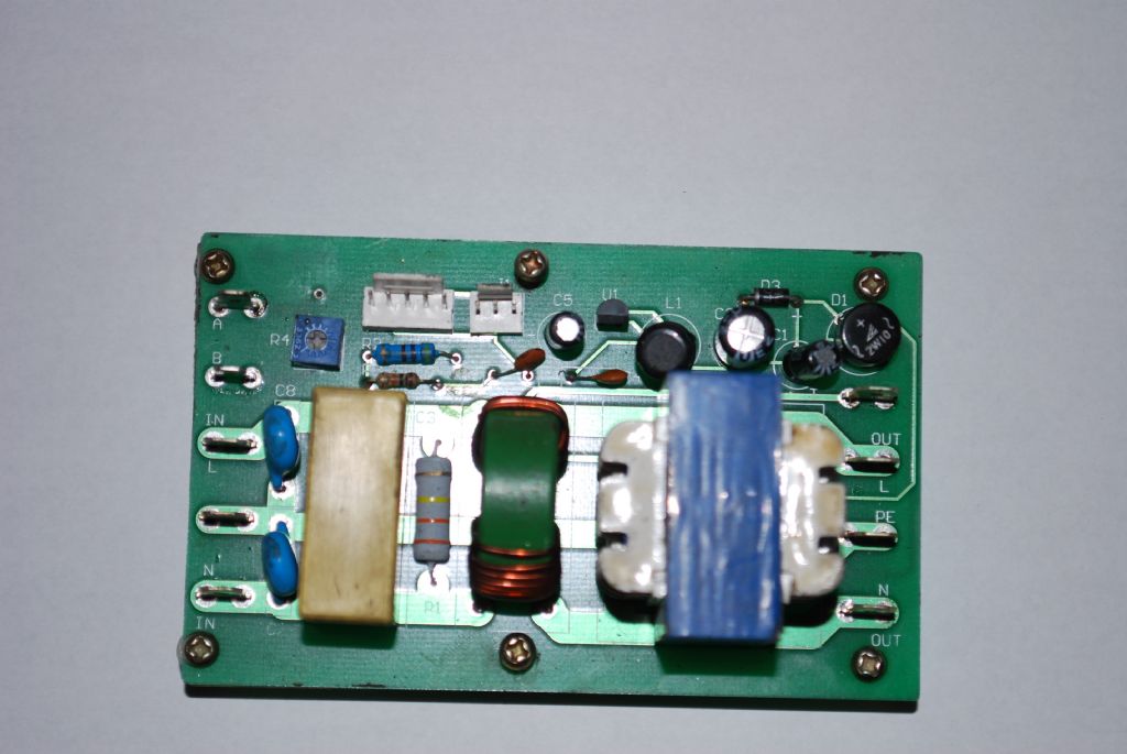
                      dsc_0091.jpgdsc_0089.jpgJohn, as requested filer board photo's. I am under the impression that the terminals you are talking about ( right hand side) are D.C. as the old motor was D.C.

                      #291212
                      John Rudd
                      Participant
                        @johnrudd16576

                        Dusty,

                        You should have two wires connected to the terminals on the left marked L and N in……this will power the board, to which you have the tacho connected….

                        The wiring that feeds the inverter, needs to be connected to the L and N terminals marked out, on the right…..

                        Just forget about the old motor and controller….

                        This should get you up and running again…..

                        Btw, the board is exactly the same as mine…and that is how I wired my inverter…

                        #291226
                        Dusty
                        Participant
                          @dusty

                          Thanks John

                          As it is my wedding anniversary today I will probably be banned from the workshop, but it should not take long to alter the wiring when I get out there.

                          #291279
                          Dusty
                          Participant
                            @dusty

                            Well, I have not been banned but told to "get out from under my feet" The wiring was altered and everything seemed O.K. except the speed display still does not work. I have checked all the connections and they seem as if they are fine. All was working prior to me pulling everything apart.

                            #291289
                            John Rudd
                            Participant
                              @johnrudd16576

                              Dusty,

                              Does the speed display light up at all?

                              Have you got a dvm/multimeter?

                              You need to check as Les suggested if you have power coming to the board…..

                              We'll go from there…

                              #291291
                              Dusty
                              Participant
                                @dusty

                                No It is dead. As the whole set up is wired through the filter board I would venture to suggest that power is present. I do have a multimeter, but as you know I do not have much of a clue as to how to use it.

                                #291296
                                John Rudd
                                Participant
                                  @johnrudd16576

                                  Dusty,

                                  Let's just recap here…..

                                  The filter board has 240 v ac mains attached to the two terminals marked In, and you have wires attached to the terminals marked Out, going to your vfd and this is working fine yes?…

                                  If that is the case, then the filter board isnt powering your display, or there is a wire adrift ……Did you check the wiring especially at the little white plug that goes to to the speed readout? Just in case a wire is broken when you removed the plug from the board……

                                  #291298
                                  John Rudd
                                  Participant
                                    @johnrudd16576

                                    I've had a look at my board, it is slightly different……

                                    Mine has one white connector on the board, not the two that yours has….

                                    My white connector has two wires that take a 5 volt supply to the speed readout….

                                    So, looking at your connectors, I'd say that on the 5 pin connector that goes to the speed indicator, the two pins at the left end, should have 5v measured between them…

                                    If you set your meter to read DC Volts on the 20 range, does your meter reading anything at those pins?

                                    DO BE CAREFUL….MAINS VOLTAGE IS PRESENT! But I'm sure you know this….

                                    Take a couple of dress making pins and insert them into the two left connections, connect the meter to the two pins with crocodile clips on the ends of the probes….( or else you could be creative and jury rig something else….but do be careful…!!)

                                    #291466
                                    Dusty
                                    Participant
                                      @dusty

                                      John

                                      Did the test on the display end of the ribbon and nothing. Upon examination I found that there were only four pins on the connector on the display, the centre one was missing. I did check to see if it was broken off inside the plug, but no. I suspect this should be in place, otherwise why have a 5 core ribbon. What are your feelings? Having taken the display apart I can see that there never was a centre pin, solder is evident on the two sets of outer pins but nothing in the centre. I will remove the 'filter' from the lathe before doing any more tests as this will be safer as I will be able to see what I am doing.

                                      Edited By Dusty on 31/03/2017 16:22:39

                                      #291479
                                      John Rudd
                                      Participant
                                        @johnrudd16576

                                        Dusty,

                                        It will be easier to work on the board with it on the 'bench'…..can you arrange a 240 v supply to the board safely?

                                        On the 5 core ribbon, what colours do you have for the cores?

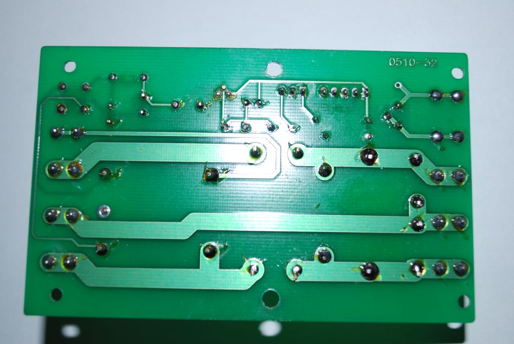
                                        can you photograph the rear of the board? A shot with the connector at the top…. Can then trace the circuit from that hopefully…..

                                        How many wires are there for the speed pickup? 2 or 3?

                                        #291481
                                        Dusty
                                        Participant
                                          @dusty

                                          John

                                          Questions I can answer The 5 core is white and each of the cores has either dots or dashes in red, most helpful, that is unless you know different. The speed pick up has 3 wires. I will not be able to strip the board from the lathe until Sunday when I will photograph it.

                                          #291491
                                          John Rudd
                                          Participant
                                            @johnrudd16576


                                            Dusty,

                                            A wild thought here….and its not personnal…..you did put the 5 wire plug back the right way round?


                                            Sunday is fine… wink

                                            More thoughts…..

                                            The display needs:

                                            2 wires for 0v and 5 volts.

                                            1 wire for the pulse input from the probe

                                            1 wire for the Contrast pin ( based on the little preset on the filter board…I could be wrong! )

                                            Hence the 4 wires…..


                                            The speed probe has 3 wires, 2 for the 5v supply, 1 for the pulses going to the filter board and from there to the display….


                                            Edited By John Rudd on 31/03/2017 17:44:31

                                            #291511
                                            Dusty
                                            Participant
                                              @dusty

                                              I will check John, but I don't think they will go in the wrong way as there is a plastic guide that sits behind the pins, this locates into a pair of guides on the plug. I will check though.

                                              #291817
                                              Dusty
                                              Participant
                                                @dusty

                                                John,

                                                I have removed the board and photographed it, as far as I can see there is nothing untoward showing. the ribbon cable appears to be O.K. without any obvious breaks in it.

                                                dsc_0098.jpg

                                                #291837
                                                Les Jones 1
                                                Participant
                                                  @lesjones1

                                                  Hi Dusty,
                                                  What is the part number printed on U1 ?

                                                  Les.

                                                  #291839
                                                  John Rudd
                                                  Participant
                                                    @johnrudd16576

                                                    Les,

                                                    U1 is a 7805 reg. Albeit in a TO92 case…

                                                    And….looking at the backside of the board, I think there are external links missing that apply power to the transformer

                                                    To be continued…..while I digest my tea and a few beers…

                                                    Edited By John Rudd on 02/04/2017 18:23:56

                                                    #291840
                                                    Les Jones 1
                                                    Participant
                                                      @lesjones1

                                                      Hi John,
                                                      Thanks for that John.
                                                      With seeing the the inductor next to it I thought that it may have been a switch mode regulator. The inductor must just be a filter. I am trying to work our what connected to the unmarked push on connector next to the bridge rectifier. I can't find it on any of the schematics. I have found. It connects with the live side of the transformer primary so it must have been linked to live via the on off switch. I suspect that there is no feed to this after the modification. I will have to look back through the thread to see if Dusty has shown how he has rewired between the filter and the NVR switch.

                                                      Edit.
                                                              I think from the way Dusty describes the way he has re wired the NVR switch and filter in his post on 15/3/17 19:35 (Page 10 of the tread.) that he does not have anyting connected to the mains output of the filter board so I think he has also missed the feed to the live side of the transformer primary. If I am right then a link beteen the live out of the filter board and the unmarked connector next to it should solve the problem.

                                                      Les

                                                      Edited By Les Jones 1 on 02/04/2017 18:54:58

                                                    Viewing 25 posts - 201 through 225 (of 245 total)
                                                    • Please log in to reply to this topic. Registering is free and easy using the links on the menu at the top of this page.

                                                    Advert

                                                    Latest Replies

                                                    Viewing 25 topics - 1 through 25 (of 25 total)
                                                    Viewing 25 topics - 1 through 25 (of 25 total)

                                                    View full reply list.

                                                    Advert

                                                    Newsletter Sign-up