Stuart Twin Victoria (Princess Royal) Mill Engine
Stuart Twin Victoria (Princess Royal) Mill Engine
- This topic has 1,285 replies, 34 voices, and was last updated 26 May 2025 at 06:48 by
 JasonB.

- Please log in to reply to this topic. Registering is free and easy using the links on the menu at the top of this page.
Latest Replies
-
- Topic
- Voices
- Last Post
-
-
Boiler Design – issue 4765
1
2
3
Started by:
Charles Lamont
in: Model Engineer & Workshop
- 17
-
1 June 2025 at 02:16
MEinThailand
-
Workshop decoration
1
2
Started by:
Sonic Escape
in: The Tea Room
- 15
-
1 June 2025 at 01:46
Pete.
-
laths and mills
Started by:
sonic_m1etn
in: Workshop Tools and Tooling
- 4
-
1 June 2025 at 00:55
Pete
-
Seig C0 baby lathe
Started by:
msrt7mcfl7
in: General Questions
- 9
-
31 May 2025 at 23:48
Sonic Escape
-
A new lathe
Started by:
Sonic Escape
in: The Tea Room
- 7
-
31 May 2025 at 23:43
Sonic Escape
-
Replacement gear
Started by:
David George 1
in: Manual machine tools
- 7
-
31 May 2025 at 22:45
John Hinkley
-
Sandvik Coromant 20mm hand-scraper
Started by:
flatline
in: Workshop Tools and Tooling
- 8
-
31 May 2025 at 22:15
Neil Lickfold
-
Gear cutting
Started by:
str8axle57
in: Introduce Yourself – New members start here!
- 8
-
31 May 2025 at 21:12
Pete Rimmer
-
Building Bernard Tekippe’s Precision Regulator
1
2
…
5
6
Started by:
Chris Raynerd 2
in: Clocks and Scientific Instruments
- 14
-
31 May 2025 at 19:57
Michael Gilligan
-
Model dynamo drawings
Started by:
Dougie Swan
in: General Questions
- 3
-
31 May 2025 at 18:38
Dougie Swan
-
The Latest INDEX to Model Engineer & Workshop (Also past issues of MEW)
1
2
Started by:
David Frith
in: Model Engineer & Workshop
- 7
-
31 May 2025 at 16:04
David Frith
-
Finding Unified rivnuts
Started by:
old mart
in: Help and Assistance! (Offered or Wanted)
- 5
-
30 May 2025 at 20:15
old mart
-
HaLifax 10″ Lathe for sale
Started by:
Richard Bartholomew 3
in: Help and Assistance! (Offered or Wanted)
- 2
-
30 May 2025 at 18:38
JasonB
-
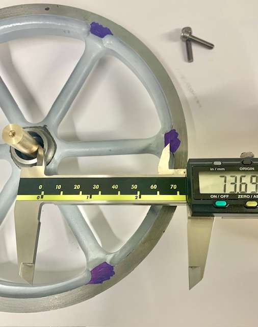
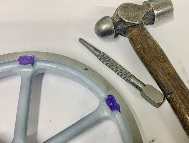
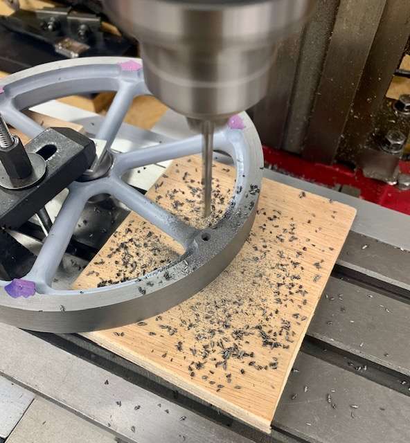
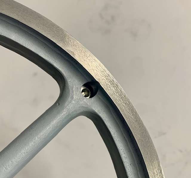
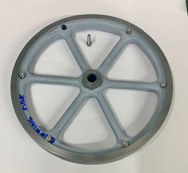
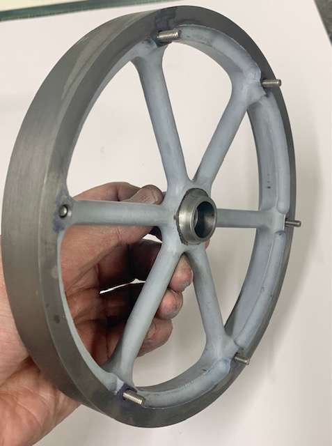
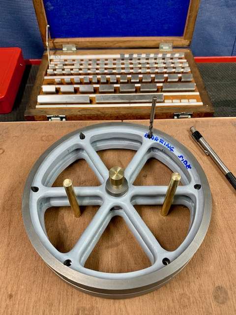
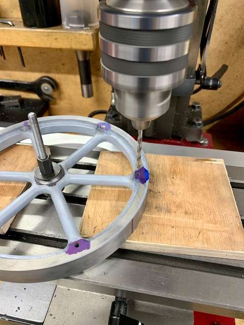
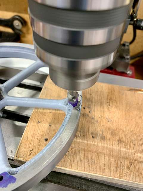
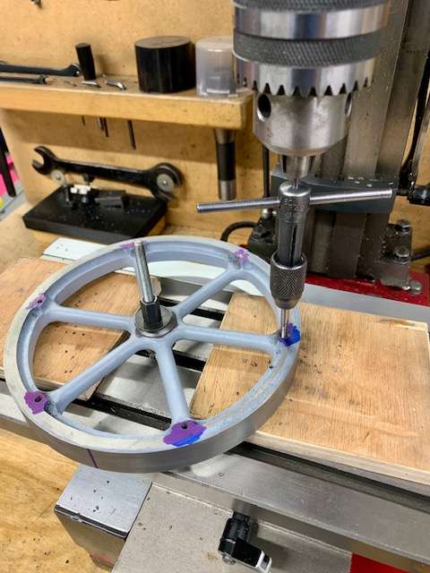
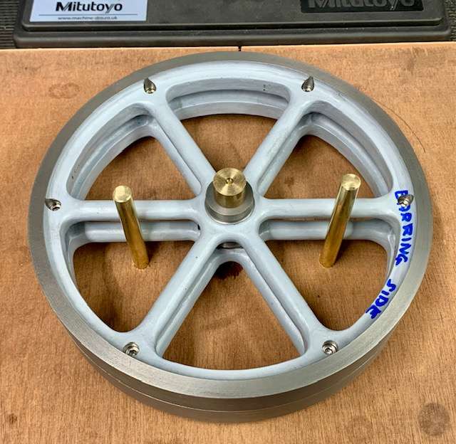
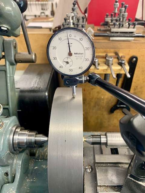
Drilling holes in blades?
Started by:
Bo’sun
in: The Tea Room
- 7
-
30 May 2025 at 17:50
Bo’sun
-
Faulty Warco 1630 Item 4085
Started by:
john fletcher 1
in: Manual machine tools
- 9
-
30 May 2025 at 17:24
Dave Halford
-
Inspection Cover fasteners
Started by:
Vic
in: Materials
- 12
-
30 May 2025 at 17:09
Nicholas Farr
-
Cooked motor
Started by:
jimmy b
in: Manual machine tools
- 5
-
30 May 2025 at 16:17
jimmy b
-
Metric Build
Started by:
danieldlonsdale@gmail.com
in: Traction engines
- 3
-
30 May 2025 at 10:39
JasonB
-
Drunk driver broke my workshop!
1
2
Started by:
stew 1
in: The Tea Room
- 15
-
30 May 2025 at 09:56
John Haine
-
Design Advice!- Warco GH600 Solid Topslide
Started by:
Richard Kirkman 1
in: Help and Assistance! (Offered or Wanted)
- 9
-
30 May 2025 at 08:58
Richard Kirkman 1
-
Stone mason query
Started by:
Plasma
in: The Tea Room
- 3
-
30 May 2025 at 07:18
Plasma
-
Alligator v the 3-Bar Overhead Slidebar arrangement
Started by:
Greensands
in: The Tea Room
- 2
-
29 May 2025 at 22:56
duncan webster 1
-
Boxford 280 Screwcutting Chart, Metric
Started by:
Nigel Bennett
in: Manual machine tools
- 3
-
29 May 2025 at 21:39
Mark Hall
-
Proxxon PD400 vs HBM 180 lathe
1
2
Started by:
Sonic Escape
in: The Tea Room
- 14
-
29 May 2025 at 21:01
Andy Stopford
-
Help me to identify and value lathes
Started by:
sammystox
in: Workshop Tools and Tooling
- 8
-
29 May 2025 at 20:21
Pete
-
Boiler Design – issue 4765
1
2
3


