Starter Switch

Advert

Starter Switch

Home Forums General Questions Starter Switch

Viewing 14 posts - 26 through 39 (of 39 total)
  • Author
    Posts
  • #321223
    Andy Sproule
    Participant
      @andysproule22368

      SOD thank you for doing that couldn't be clearer.Wired it up to light first soon as I turned power on at mains the coil kicked in and the light came on and it would not disengage when I pressed the stop button.Tried it hooked up to motor the motor tried to start but then stopped.Hooked it back up to light now light won't come on.Any ideas?

      Advert
      #321237
      Mike Poole
      Participant
        @mikepoole82104

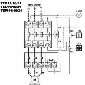
        teb1116217.jpgHas the overload tripped? Stop button should reset o/l. Coil should not energise as soon as you apply power the start and stop button both need to be in circuit and the auxiliary contact makes a seal by being in parallel with the start button, this is a classic circuit and there are plenty of diagrams of it on the net.

        Mike

        Edited By Mike Poole on 13/10/2017 08:49:00

        #321251
        SillyOldDuffer
        Moderator
          @sillyoldduffer
          Posted by Andy Sproule on 13/10/2017 01:01:08:

          SOD thank you for doing that couldn't be clearer.Wired it up to light first soon as I turned power on at mains the coil kicked in and the light came on and it would not disengage when I pressed the stop button.Tried it hooked up to motor the motor tried to start but then stopped.Hooked it back up to light now light won't come on.Any ideas?

          Hi Andy,

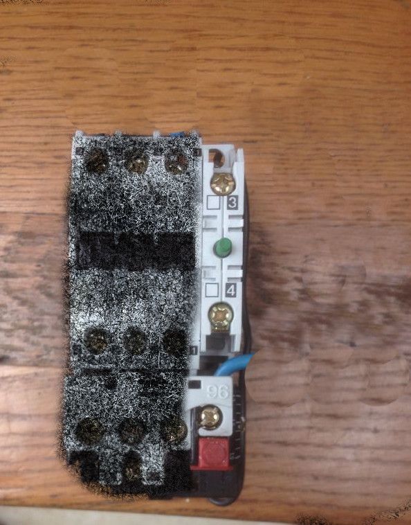
          As Mike says the coil shouldn't kick in. I think the motor/power part of the wiring is correct and there's something wrong with the control & on/off switch connections. We need to look at the wiring on the right hand side of the contactor. Can you put up some photos please?

          contactorsw.jpg

          What's needed is close to the circuit on the right hand side of Mike's post. Bit confusing because that's for a 3-phase set-up and you have single-phase.

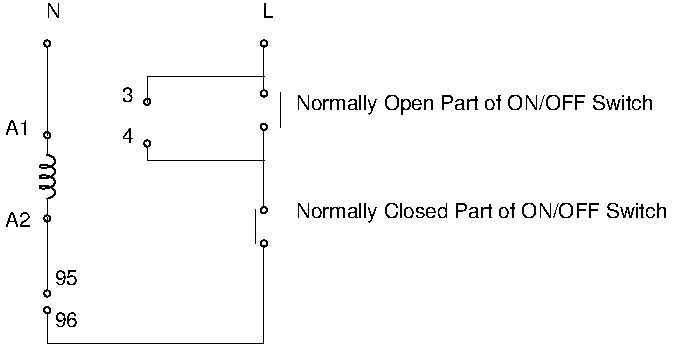
          I think you want this:

          contactorctrl.jpg

          Where,

          • A1 and A2 are the contactor coil.
          • 95 and 96 are the terminals on the thermal cutout
          • 3 and 4 are the terminals on the right hand side of the contactor
          • L and N are the mains input ( L1 and L3 on the contactor)

          The unknown is the ON/OFF switch. With luck it will have terminal pairs marked 'NO' for normally open and 'NC' for normally closed. A photo would help.

          WARNING! I've assumed that your contactor coil is mains operated and won't burn out when mains is applied. My experience is with relays rather than contactors, where the relay coil is worked by a lower voltage than is being switched.) Given the diagrams published by Mike and Brian, I think I'm on safe ground but I'd be grateful if a contactor expert could confirm please!

          Dave

          #321263
          duncan webster 1
          Participant
            @duncanwebster1

            Where is 95? SOD's diagram agrees with Mike Poole's, but suggests that 95 and 96 should be shorted together as they are to allow an external stop switch. It certainly should not operate as soon as the mains is connected. The only way this can happen is if 3 & 4 have been shorted

            #321264
            Andy Sproule
            Participant
              @andysproule22368

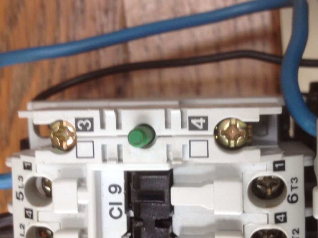
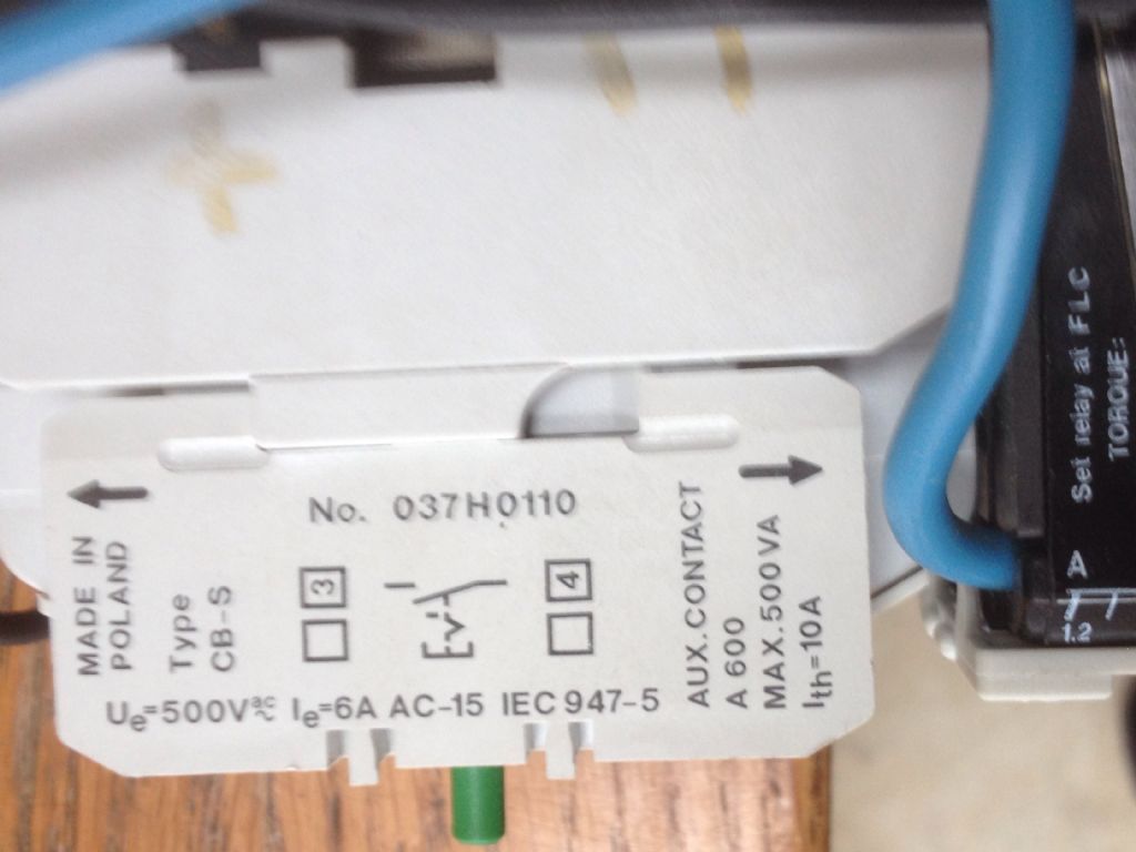
              img_2726.jpgSod I wired it as in your picture. Also A1 is connected to 1L1 and 5L5 is connected to 96 just above red button.There are no wires connected to 3 and 4 on the on the right hand side on off switch.img_2725.jpg

              #321267
              SillyOldDuffer
              Moderator
                @sillyoldduffer
                Posted by duncan webster on 13/10/2017 11:48:19:

                Where is 95? SOD's diagram agrees with Mike Poole's, but suggests that 95 and 96 should be shorted together as they are to allow an external stop switch. …

                Hi Duncan,

                I think 95 is near 96 on the right hand side but hidden underneath. If you look closely there's a black wire in Andy's photo leading to it.

                95 and 96 are a normally closed switch inside the thermal cutout. It opens on overload, phase loss, or if the red button is pressed. (The red button may also be a reset, to be pushed after an overload?)

                Dave

                #321268
                Andy Sproule
                Participant
                  @andysproule22368

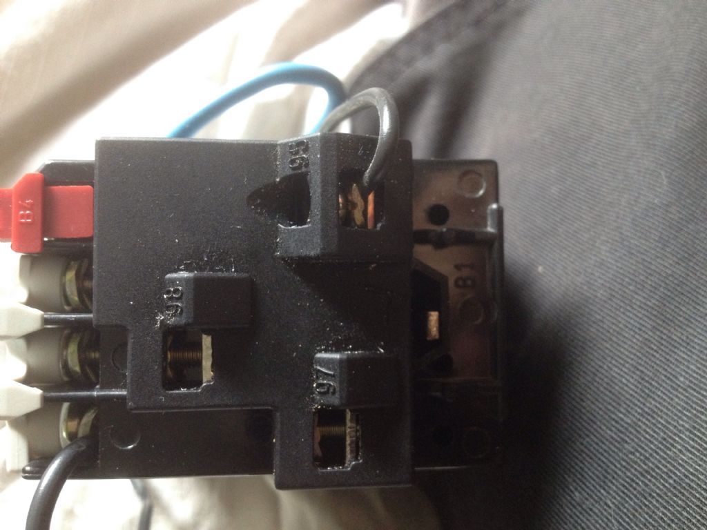
                  SORRY correction from last post 5L5 SHOULD HAVE BEEN 5L3.Hi Duncan,this is a pic of the underside 95 on the right is connected to A2 by that black wire.96 is connected to 5L3 by blue wire.img_2727.jpg

                  #321276
                  SillyOldDuffer
                  Moderator
                    @sillyoldduffer
                    Posted by Andy Sproule on 13/10/2017 11:49:40:

                    img_2726.jpgSod I wired it as in your picture. Also A1 is connected to 1L1 and 5L5 is connected to 96 just above red button.There are no wires connected to 3 and 4 on the on the right hand side on off switch.img_2725.jpg

                    Hi Andy,

                    'Also A1 is connected to 1L1 and 5L5 is connected to 96 just above red button.'

                    That explains why the coil operates. It's connected directly across L and N. Good news because it makes sense even though it's not right.

                    With a lamp as the load, try this:

                    • Disconnect A2 at the 5L3 end and reconnect the wire to 95.
                    • Disconnect A1 at the 1L1 end and reconnect the wire to 5L3. A1 is now mains neutral.
                    • Confirm 96 is wired to the ON/OFF switch
                    • Confirm the ON/OFF switch has mains L on the other side, i.e is connected to 1L1
                    • Cross fingers, apply power, and press ON

                    'There are no wires connected to 3 and 4 on the on the right hand side on off switch.'

                    3 and 4 are auxiliary contacts needed to latch the contactor on when the ON button is a momentary type (like a push switch that goes on when you press it and off as soon as you let go.) With luck you may not need 3 and 4 . It depends on whether or not your ON/OFF switch physically latches when pressed. Try it and see. If lamp only stays on whilst the ON button is held down, we will need to wire in 3 and 4.

                    Once the lamp is properly controlled by the ON/OFF switch, try connecting the motor. (There may be a problem in that department too, but let's get the contactor working properly before worrying about it.)

                    Dave

                    #321289
                    Emgee
                    Participant
                      @emgee

                      Hi Andy

                      Best and safer for you to have someone call round and connect the starter for you, it seems you may get there in the end but it all makes painfull reading.

                      You haven't confirmed yet the overload rating is suitable for the new single phase motor.

                      Just post your postcode and maybe a forum member with electrical knowledge will help you out.
                      Failing that suggest you contact a local electrician.

                      Emgee

                      #321297
                      Brian Sweeting 2
                      Participant
                        @briansweeting2

                        It is often safer to remove all previous wiring and start afresh following a wiring diagram.

                        #321355
                        Mike Poole
                        Participant
                          @mikepoole82104

                          The overland unit you are using has a current range of 1.2A to 1.9A if the FLC (full load current) of the motor you are using is higher than this then you need a new overload unit. If you look at the rating plate on your motor is should specify the FLC of the motor, I suspect that if this was correctly sized for the 3 phase motor on the bandsaw and you have replaced with a same horsepower single phase then the FLC will be too high for that overload and that is why tripped.

                          Mike

                          #321446
                          Andy Sproule
                          Participant
                            @andysproule22368

                            Well folks the the saw is up and running.Thank you all for your help.Dave thank you for sticking with it.

                            #321449
                            SillyOldDuffer
                            Moderator
                              @sillyoldduffer
                              Posted by Andy Sproule on 14/10/2017 18:26:34:

                              Well folks the the saw is up and running.Thank you all for your help.Dave thank you for sticking with it.

                              Well done Andy – very satisfying when something reluctant is coaxed back into service!

                              Dave

                              #321452
                              Brian Sweeting 2
                              Participant
                                @briansweeting2

                                Well done Andy, it must be tricky getting it going again with so many people in the workshop with you. laugh

                              Viewing 14 posts - 26 through 39 (of 39 total)
                              • Please log in to reply to this topic. Registering is free and easy using the links on the menu at the top of this page.

                              Advert

                              Latest Replies

                              Home Forums General Questions Topics

                              Viewing 25 topics - 1 through 25 (of 25 total)
                              Viewing 25 topics - 1 through 25 (of 25 total)

                              View full reply list.

                              Advert

                              Newsletter Sign-up