Restoring Beaver VBRP Mill

Advert

Restoring Beaver VBRP Mill

Home Forums Manual machine tools Restoring Beaver VBRP Mill

Viewing 25 posts - 26 through 50 (of 182 total)
  • Author
    Posts
  • #139598
    Paul Major
    Participant
      @paulmajor25237

      The top surface of the knee looks to be in pretty good condition as well.

      [​IMG]

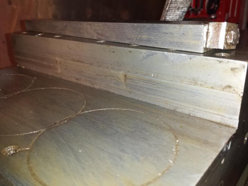
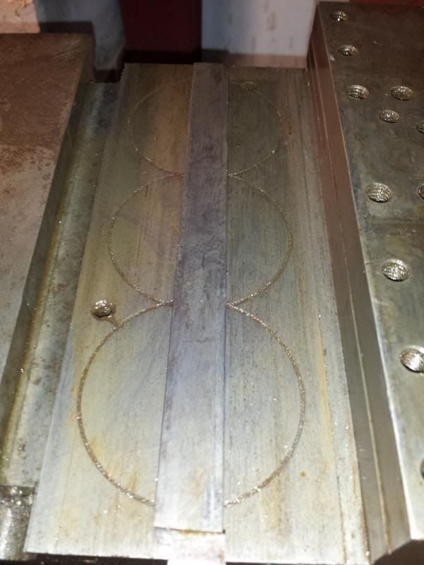
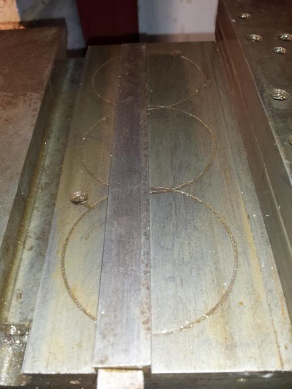
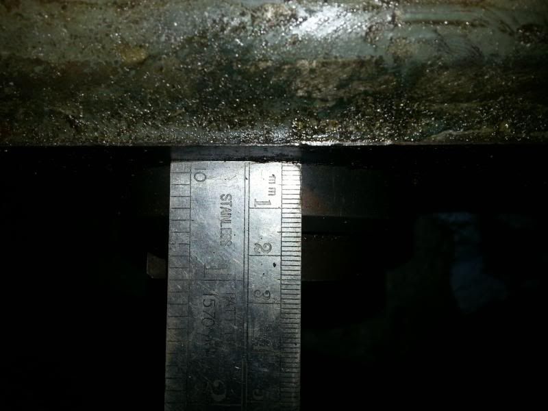
      Of more concern is the outside edge of the keyway which has some obvious wear towards the front.

      At a guess it looks like the gib has been too tight and has worn a grove at this end.

      [​IMG]
      [​IMG]

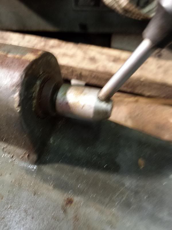
      The opposite side is fine but there is a definite groove worn here. Not sure how much impact this will have on the accuracy of the mill. Have run a DTI across it and it is about 5 thou deep, peaking at 10 thou where the line is in the middle of the groove.

      So, the big question is, what sort of tolerances/wear should I deem acceptable on a mill like this. When built it will be used for mainly engine work, skimming heads, fly cutting etc.

      I didn’t get a chance to see it up and running when I bought it so don’t really have a good idea of how tight it was. With the knee in place it is way too heavy to feel any movement in the knee and I haven’t reassembled the saddle to check this.

      Have seen threads on scraping etc but was hoping to avoid this if possible.

      So, what’s the collective wisdom here, what should I accept on the mating faces and how should I go about improving them?

      Cheers,

      Paul.

      Advert
      #139703
      Paul Major
      Participant
        @paulmajor25237

        Pretty miserable weather outside and still too windy to go up and replace the tiles lost from the roof over the last week soooo,

        More time in the workshop party

        Continued with the cleaning of the knee. First job was to remove the handle and mic ring etc from the knee feed screw. After the huge effort it took to get the saddle feed handle and leadscrew out I have to say i wasn't looking forward to it!

        In the end it took about 5 mins smiley. Whereas the other mic ring was rusted solid this one was nicely greased up. Took out the mic ring locking screw and the ring just popped off.

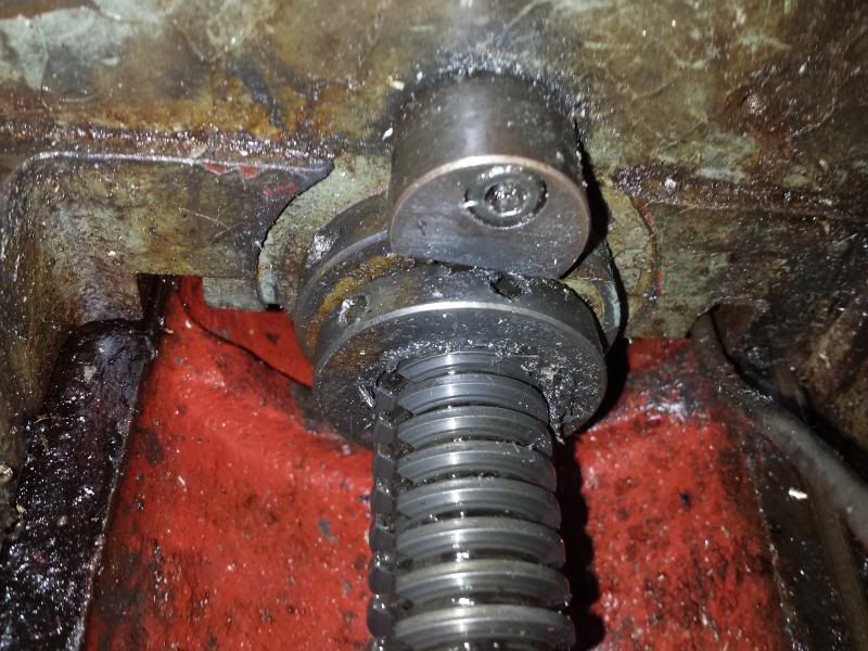
        The collet the ring sits on had the same set up as the saddle, one obvious grub screw, a tapered pin and one less obvious grub screw under the ball bearing on the mic ring lock.

        After removing these the collet ring itself came off really easily and then the Hoffman bearing and the 2 machine screws holding the spacer ring onto the knee could be taken off.

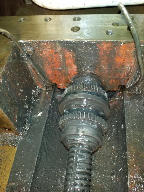
        I had already unscrewed the knee pillar from the riser screw so now the complete leadscrew/gears/riser came out as one unit after removing a couple of machine screws that held it to the knee.

        The motor for the knee is a later addition. The bevel gear on the end of the leadscrew is held on with a tapered pin, once this is removed the leadscrew pulls out of the carrier.

        Next job was to remove the knee retaining plates and gibs.

        Started by removing the handle from the knee lock.

        The shaft this operates on is attached to one of the retaining plates as you will see in a minute.

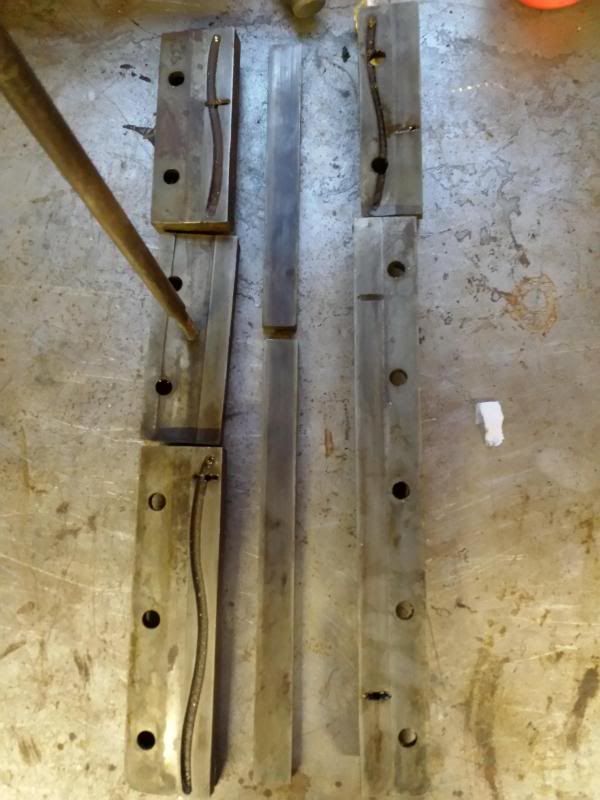
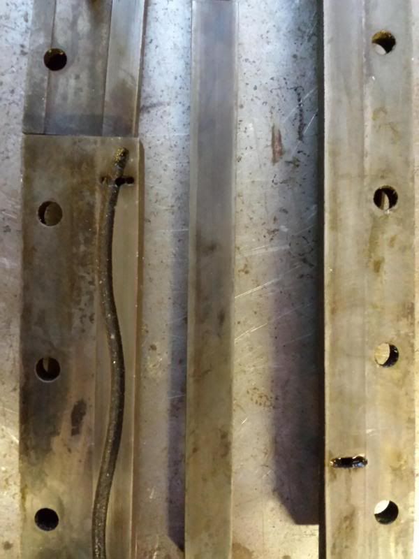
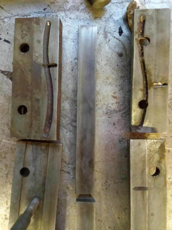
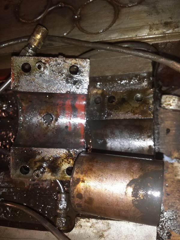
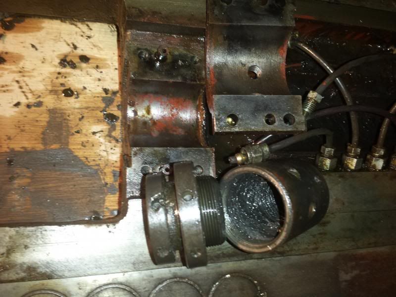
        Said retaining plates were removed along with the gibs. These are straight gibs on the knee adjusted by a series of grub screws. Some pics of the plates and gibs.

        I don't know if the grease points or channels were a later addition but it seems odd that 4 plates have "s" shaped channels and 1 doesnt, and on 3 of the plates the grease point is drilled into the channel and on 1 it isnt!

        Plates and gibs look kinda OK, but not got any real experience to go on here about how to check/measure.

        What was noticeable was the adjustment on the gibs seemed odd. The top grub screw (in the picture) was snapped off and the middle and bottom ones both had been wound in about 2-3mm whereas the ones in between were flush.

        This implies to me the gibs on the knee hadn't been properly adjusted, but I'm no expert!.

        I could then give the whole knee a wash down to get all the oil/grease/rubbish off and set it to one side ready for refurbing. I am soooooo enjoying having my new beam, trolley clamp and chain block, it is making this project so much easier laugh

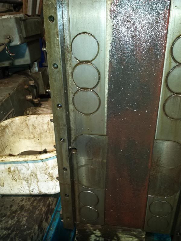
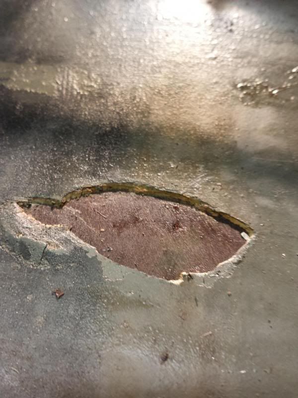
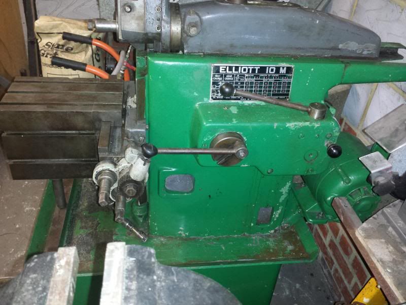
        Just out of interest, as part of the refurb I was planning on stripping and painting the mill. This pic gives you an idea of how much filler/effort they put into prepping the mill for paint when it was first produced.

        Cheers,

        Paul.

        Edited By Paul Major on 05/01/2014 00:23:02

        #139717
        Michael Gilligan
        Participant
          @michaelgilligan61133

          Paul,

          This is heroic work you are doing.

          Sorry I have nothing to contribute but my thanks, for taking the trouble to document your journey.

          MichaelG.

          #139732
          Paul Major
          Participant
            @paulmajor25237
            Posted by John Stevenson on 31/12/2013 20:34:35:

            having said that do you have 5" on this model or 6" ?

            Hi John,

            not sure if the quill is 5" or 6" yet, head and arm will probably be the last bit I refurb.

            Thanks for the encouragement Michael, makes a difference when you spend hours writing this stuff up

            Hopefully helps someone else out as well and gets me a bit of good advice along the way.yes

            Cheers,

            Paul.

            #139749
            Russ B
            Participant
              @russb

              Hi Paul,

              I don't think I have any pictures on me, certainly not on my home PC, I'll ask about and see if anyone knows if we've any documentation or info on it.


              It's looking good !


              Edited By Russell Bates on 05/01/2014 13:42:57

              #139829
              Russ B
              Participant
                @russb

                Paul,

                I do have the full maintenance and service manual for the Beaver MK2, including exploded views of everything and full parts lists, wiring diagrams etc.

                Let me know if you need a copy.

                Regards,

                Russ

                #139857
                Paul Major
                Participant
                  @paulmajor25237
                  Posted by Russell Bates on 06/01/2014 10:47:17:

                  Paul,

                  I do have the full maintenance and service manual for the Beaver MK2, including exploded views of everything and full parts lists, wiring diagrams etc.

                  Let me know if you need a copy.

                  Regards,

                  Russ

                  Hi Russ

                  Thanks for the offer. The handbook I have is titled "Instruction Manual Beaver VBRP Mk2 Turret Miller" and is 50 pages. Has some parts diag's and info on belts etc but not terribly detailed.

                  Is that the same as yours?

                  Thanks,

                  Paul.

                  Edited By Paul Major on 06/01/2014 15:57:02

                  #139858
                  Russ B
                  Participant
                    @russb

                    Hi Paul,

                    Mine is 47 pages and titled "Beaver Mill MK2, Operator's and Maintenance Manual"

                    it features information on adjustment of many items and an exploded view each assembly (head, ram, column, knee/saddle & table, various feed gearboxs, clutch box and so on) – here's one of the exploded views to give you an idea.

                    When I gathered information on my Bridgeport I found various manuals but struggled to find "the right one" for it, as well as detail issue, I now have a collection of slightly different manuals some old, some new, showing different version, some have section views, others exploded, between them, I have a pretty good idea of what's going on (although when it comes to stripping things down, there's nothing like following in someone's foot steps smiley (the number of times I've had to google things……)

                    #139863
                    Paul Major
                    Participant
                      @paulmajor25237

                      I know what you mean on the Googling

                      In that diagram it references the Knee feed gearbox assembly diagram, don't suppose you have that do you?

                      Does it cover anything on the setting up of gibs etc?

                      I guess easiest answer is a copy of the contents page then I can compare it to mine

                      Cheers,

                      Paul.

                      #139868
                      Russ B
                      Participant
                        @russb

                        Paul,

                        Here's the manual, get it while its hot – if its even slightly different to your own, it might just give you the slightly different angle or better clarity on any one picture or diagram that could help out – so enjoy, now I'm off to get my hands very dirty removing my J head to change the feed select shaft around 180°………..frown

                        https://www.dropbox.com/s/xjped2vq7ywp240/Beaver%20Mill%20Mk2.pdf

                        I can't promise to host this for extended periods since I only have limited space but I'll leave it up for the time being.

                        let me know if you have any issues with downloading it

                        Edited By Russell Bates on 06/01/2014 18:15:05

                        #140122
                        Paul Major
                        Participant
                          @paulmajor25237

                          Thanks Russell, all safely downloaded yes

                          It is slightly different to mine so that's great, all knowledge is good knowledge

                          Back to cleaning duties now – what a pain cleaning 300kg lumps of metal is!!

                          Cheers,

                          Paul.

                          #140172
                          Paul Major
                          Participant
                            @paulmajor25237

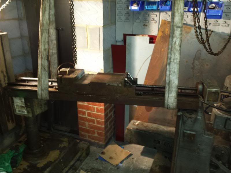
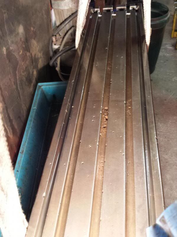
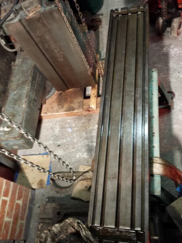
                            With the knee stripped and cleaned it was time to move on to the table. A bit more playing with block and tackles and we have the table mounted ready for work .

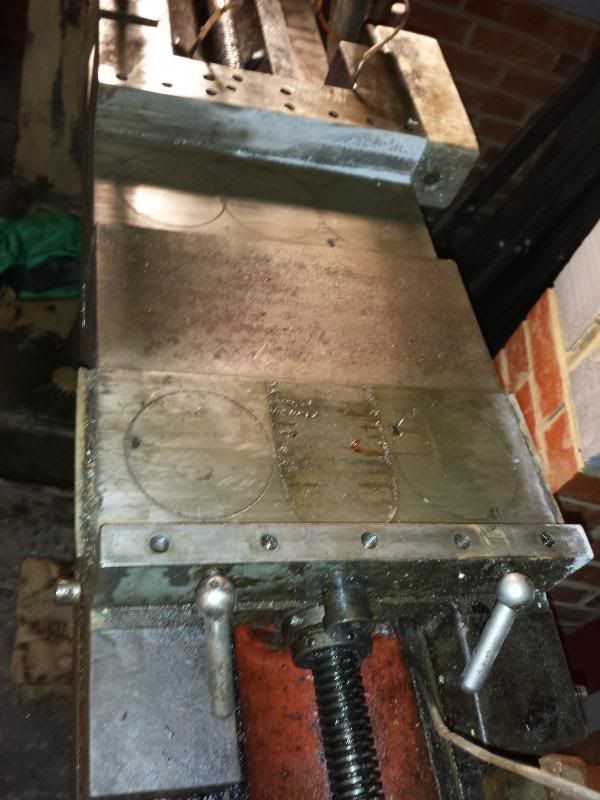
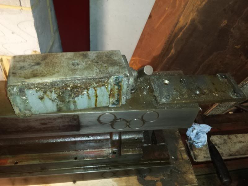
                            The table is upside down obviously (and weighs a ton!) but this allows me to check out the ways/mating surfaces on the saddle to knee area.

                            The last pic shows the two locking pins that lock out the saddle to knee.

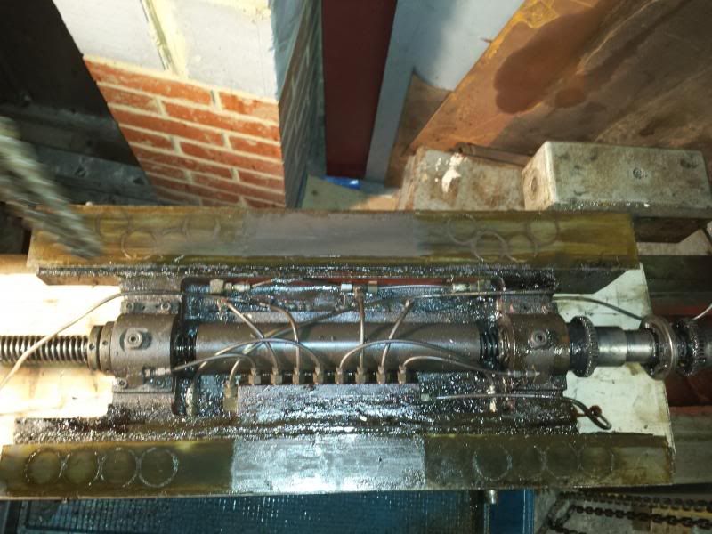
                            Next step I thought was to remove the leadscrew but I couldn’t see any way of doing this with the saddle in place, so the saddle came off. I guess if it was all assembled this would be the same procedure for removing the table.

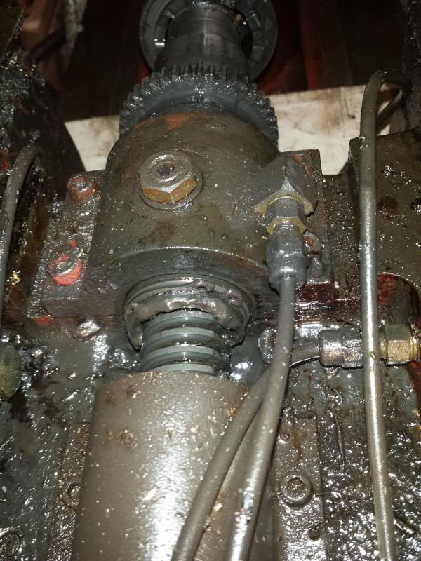
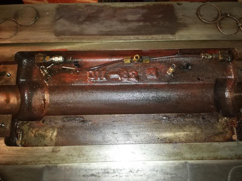
                            The saddle is held in place with two tapered gibs adjusted by a double nut arrangement (forgot to take pictures). With the gibs removed the saddle can be lifted off the table ways to reveal a spaghetti junction of oil pipes where someone had fitted an auto oiler!smile o

                            One side of the saddle is what the manual refers to as a “table feed gearbox assembly”. To be honest I haven’t got my head around how this works as the table and saddle where already removed when I picked up the mill.crook

                            The other side of the table is the backlash adjustment screw together with a retaining collar.

                            So that’s the saddle off, next job, remove the leadscrew.

                            Cheers,

                            Paul.yes

                            #140175
                            Paul Major
                            Participant
                              @paulmajor25237

                              The leadscrew has two motors, a rapid return and a slow feed. Again the manuals only show hand screws for the table feed but I know the rapid return was an option on these mills – just don’t know which end is which laugh

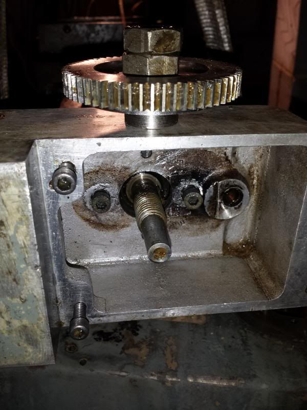
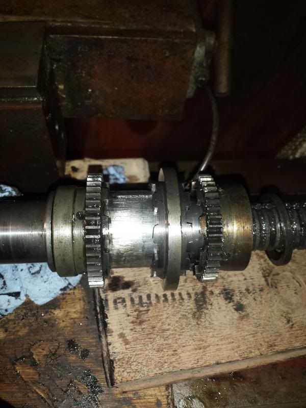
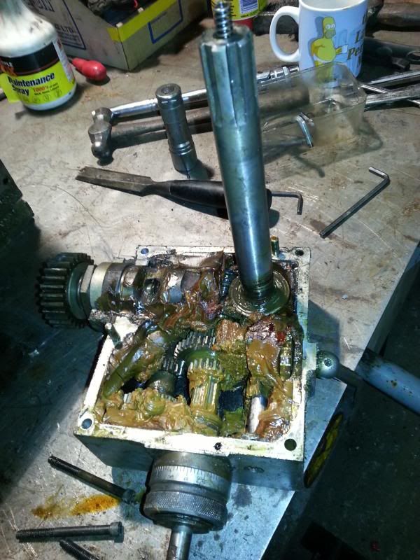
                              So removed the gearbox cover plate and waded through masses of greases to find a cog held on by a double nut.

                              Removing this allows you to remove two bolts that hold the gearbox to the table end bracket. This houses the bearing the end of the leadscrew runs in and is located on 2 dowels.

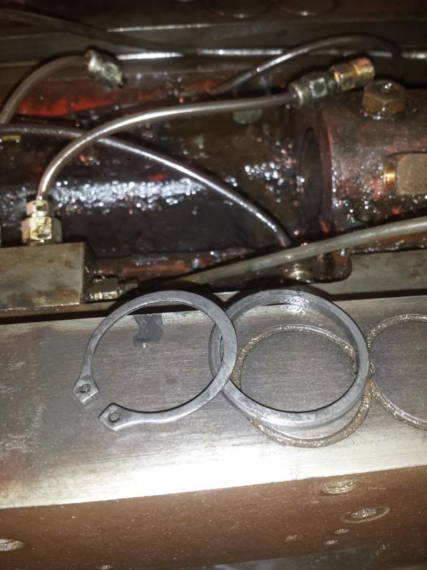
                              The table feed gearbox assembly is held in place on the leadscrew with a circlip and thrust washer.

                              Having loosened the gears at one side of the saddle and backed of the backlash adjustment collar on the other side I then gradually removed the oiler reservoir and tubing.

                              The leadscrew sits in 2 bushes held in place by bearing caps

                              With the caps, tubing, and shield removed the leadscrew will then lift off the table.

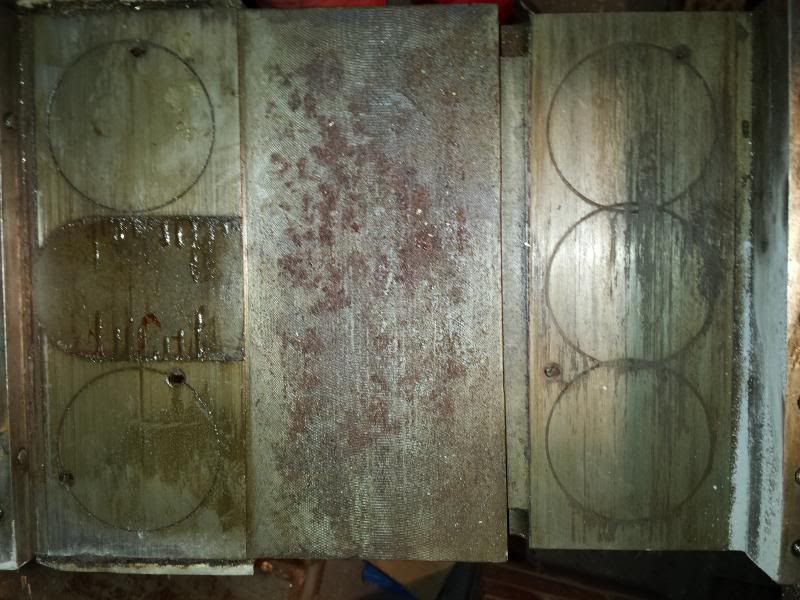
                              Having cleaned up the saddle some more I gave it a closer inspection. These are the ways that match up to the outside of the saddle. They seem to have matching grooves worn in them.

                              I wonder if at some point swarf has become lodged in-between these two surfaces and scored the surface. As mentioned above when discussing the knee, my challenge will be deciding whether it is worth trying to reface these surfaces, or whether to refit the saddle to the knee and once adjusted with the gib, ascertain if it causes any real tolerance issues.

                              The saddle to knee gib looks in reasonably good condition.

                              So that’s it, saddle and table stripped, now onto some more cleaning sad

                              Cheers,

                              Paul.

                              #141739
                              Paul Major
                              Participant
                                @paulmajor25237

                                Not been able to do any updates for a while, broadband has been down. Took BT a week and 3 different engineers visiting to get it working again angry 2

                                Anyway got to work on the table. Tried various approaches ended up going over it with a brass wire brush after lots of attacks with degreaser. Not sure it will ever end up looking like one of those nice new polished chrome looking mills but at least its clean

                                Cheers,

                                Paul.

                                Edited By Paul Major on 26/01/2014 13:49:06

                                #141740
                                Paul Major
                                Participant
                                  @paulmajor25237

                                  Got bored with cleaning so decided to strip down the head. This unit has a thumping great 2 speed electric motor sitting ontop of the 8 speed belt system. Not sure yet how many speeds that gives but it seemes a lot laugh

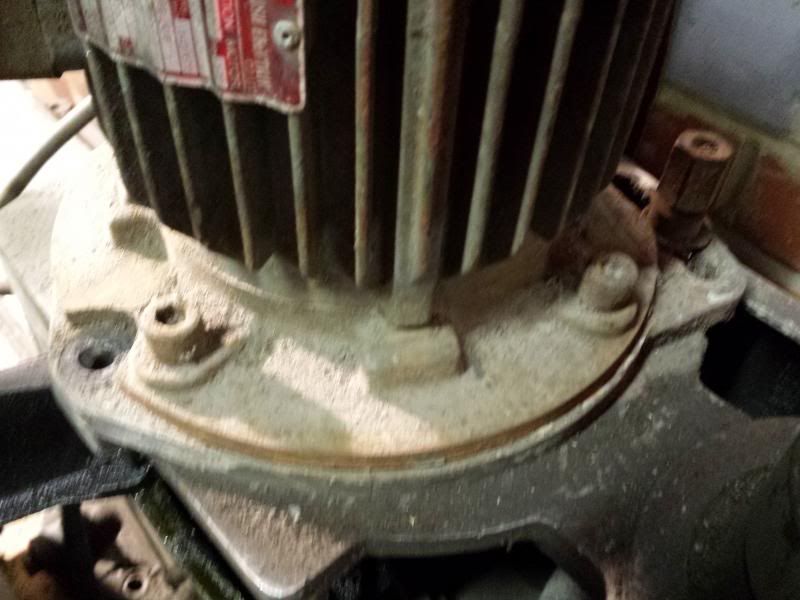
                                  The motor is held in situ by 3 bolts and is on a moveable plate to allow for tensioning of the belts.

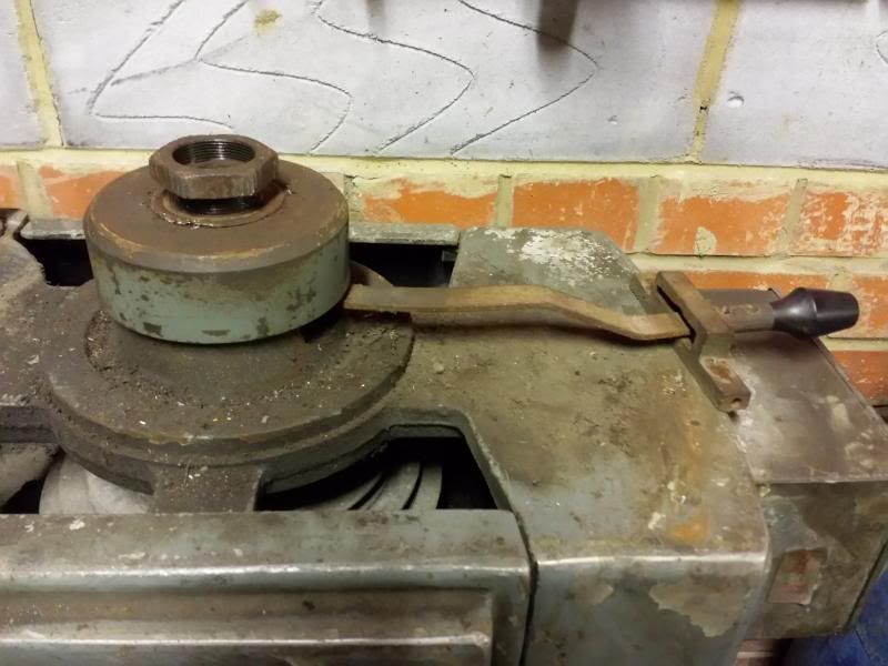
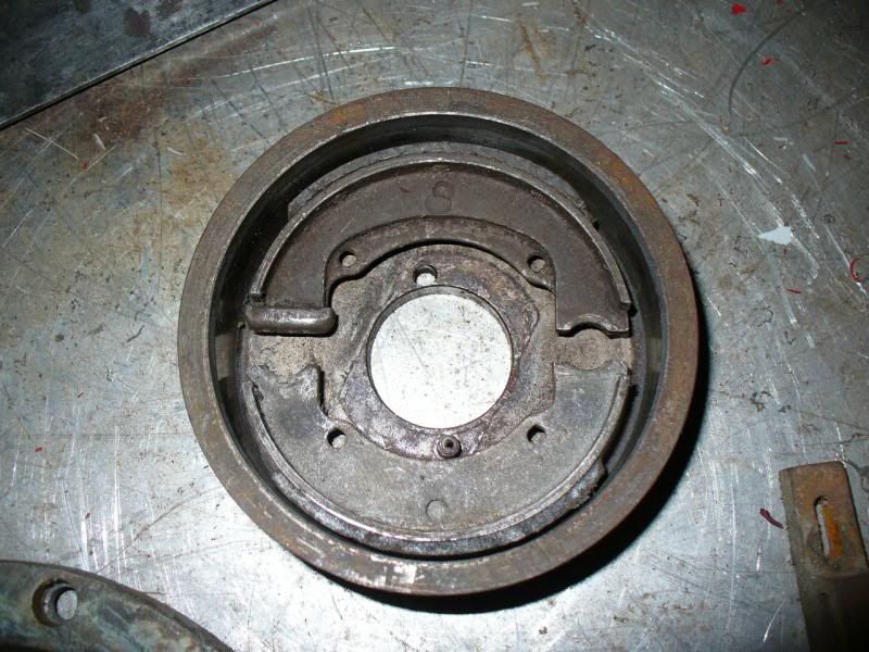
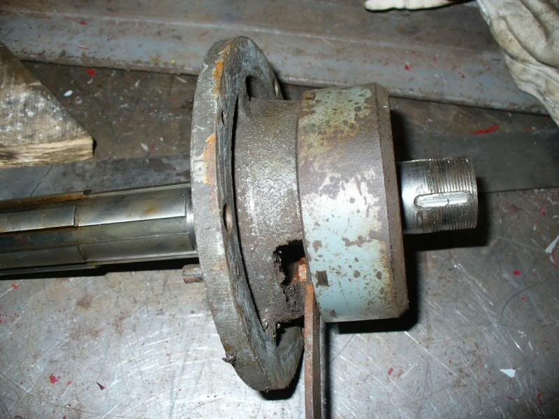
                                  The head also has a lever operated braking system that sits on top of the main spindle.

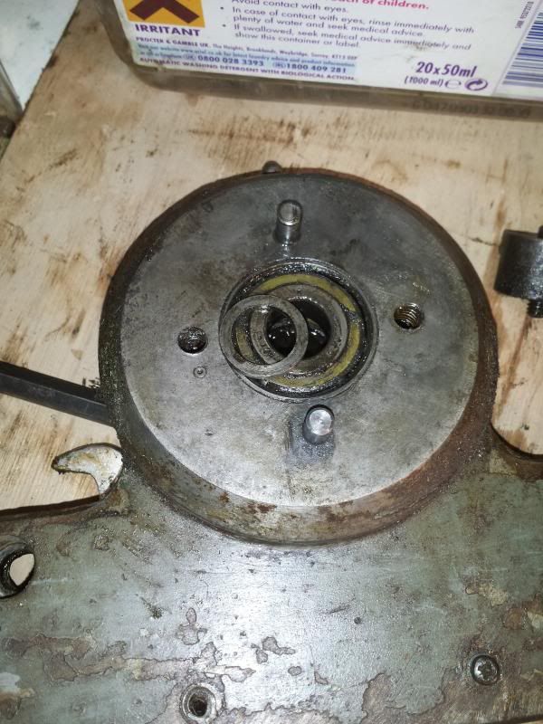
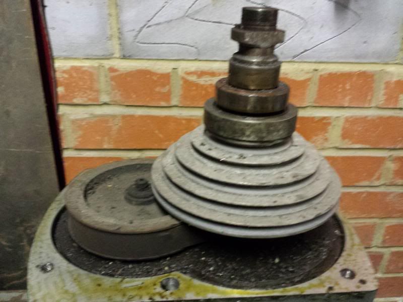
                                  Undo the locking washer and nut on top and the brake "drum" together with expanding shoes pops off the top of the spindle. The pulley cover can then be removered after undoing about 6 hex head bolts.

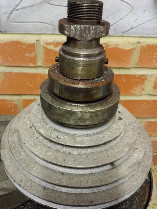
                                  In the picture below the top part is where the brake mechanism sits then there is a bearing beneath.

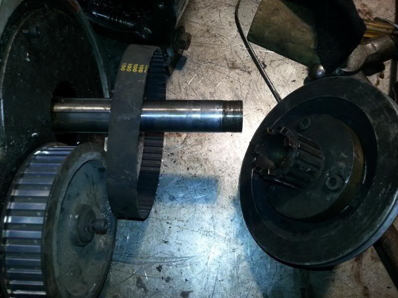
                                  Underneath this is the second pulley wheel which is connected to the main drive shaft via a toothed belt.

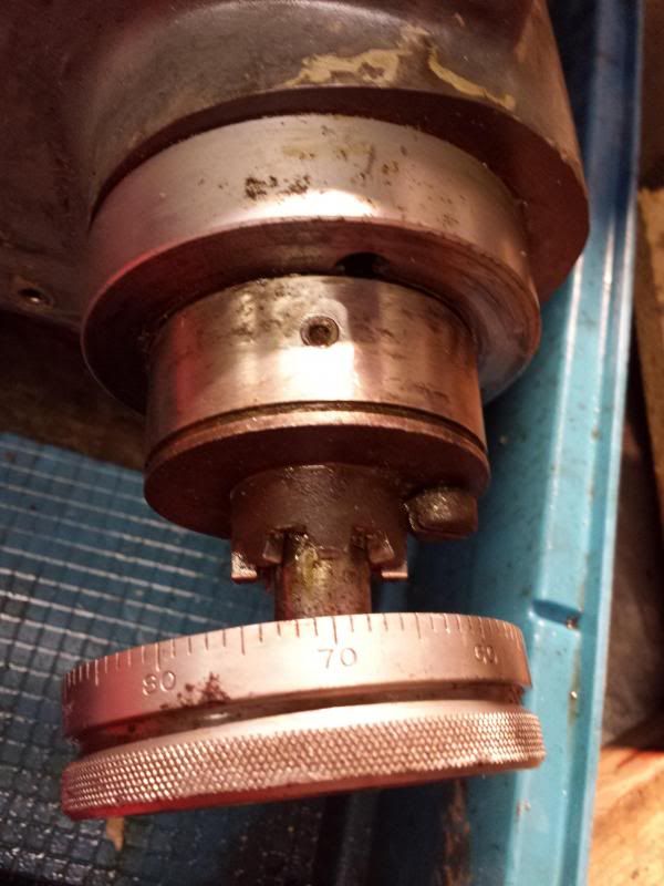
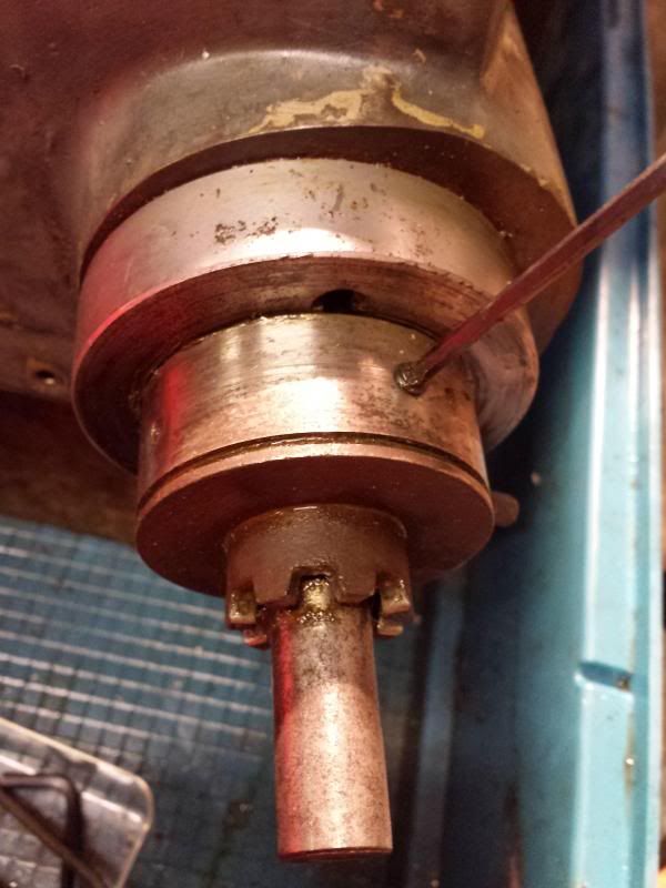
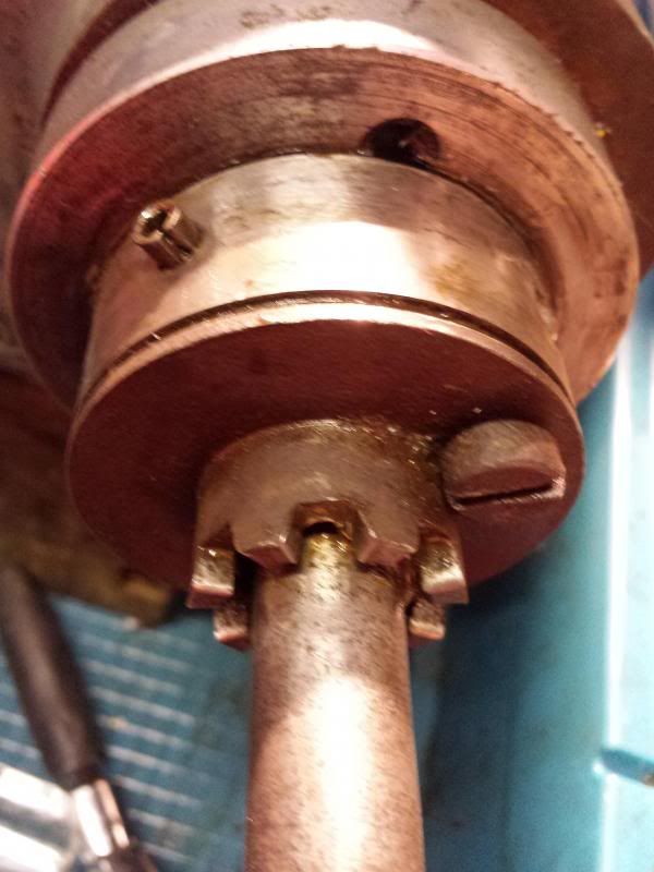
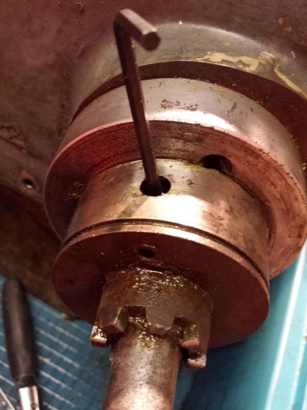
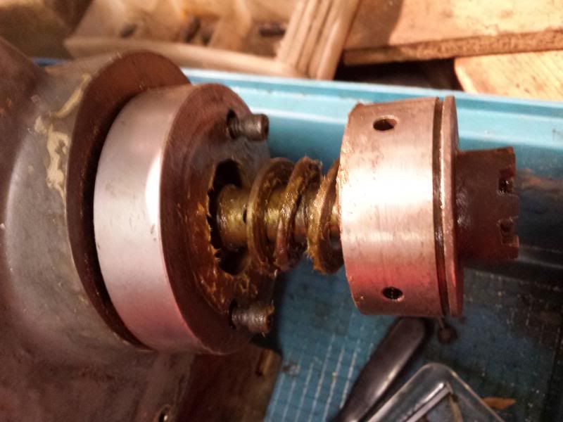
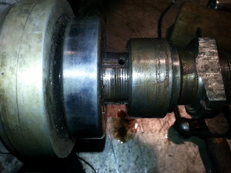
                                  At this stage I tried to remove the brake attachment from the top of the spindle but couldn't see how it was attached. It does have a couple of grub screws as seen in this photo

                                  but even with these backed of I couldn't budge it. It looked like it was threaded on but turning the top just wound the quill in and out so I left it in situ for the moment.

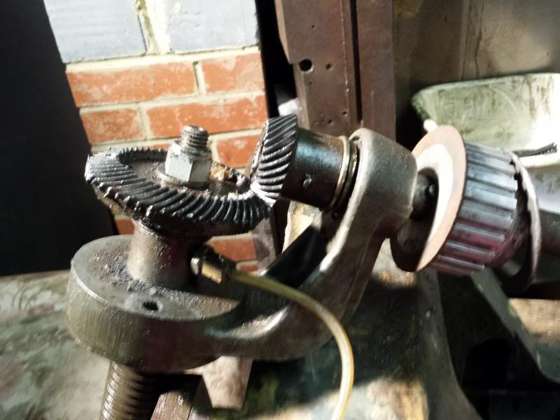
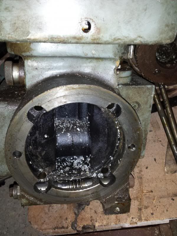
                                  Having got the motor off I decided it would be easier to work on the head on the bench, so 4 large bolts on the front face of the head were removed and the the head will seperate from the arm.

                                  In this pic you can see the screw/gear arrangement that allows you to cant the head from side to side (it will swivel 180 deg on these almost making it into a horizontal miller)

                                  Cheers,

                                  Paul.


                                  Edited By Paul Major on 26/01/2014 14:05:35

                                  #143369
                                  Paul Major
                                  Participant
                                    @paulmajor25237

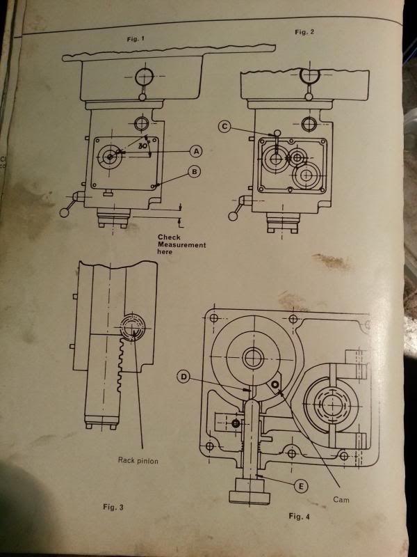
                                    With the head off next job was to remove the quill. In answer to John's question last month the quill moves just under 5 1/2", which I guess makes it a 5" ?

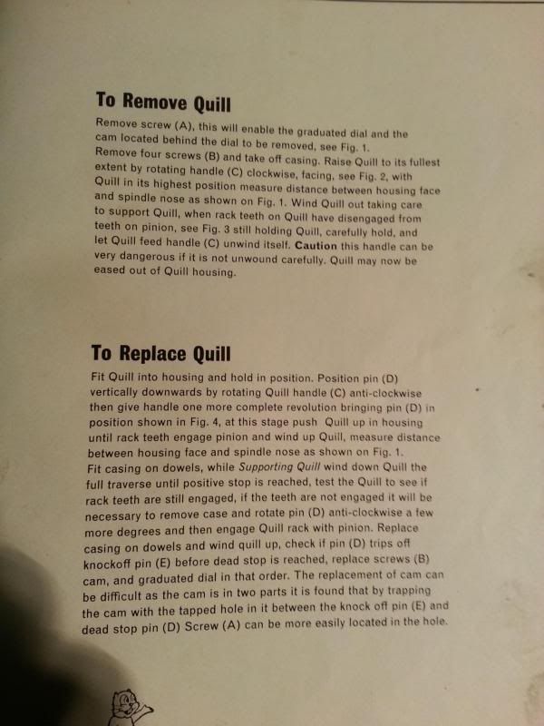
                                    Removing the quill is about the only thing the manual gives instructions on so I will include it here incase it is of use!

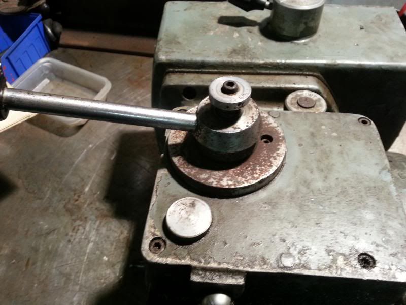
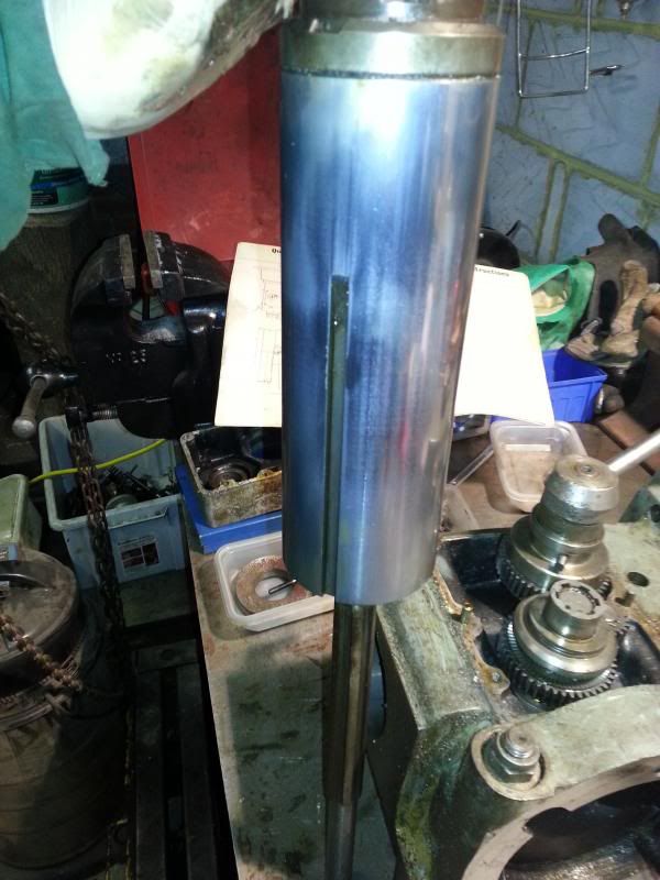
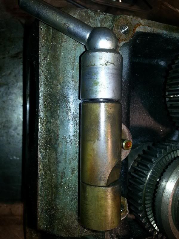
                                    Setup for quill downfeed handle looks like this, mine is missing the micrometer dial

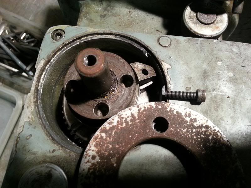
                                    and removed shows the cam arrangement, (roughly 2 o'clock on the photo),

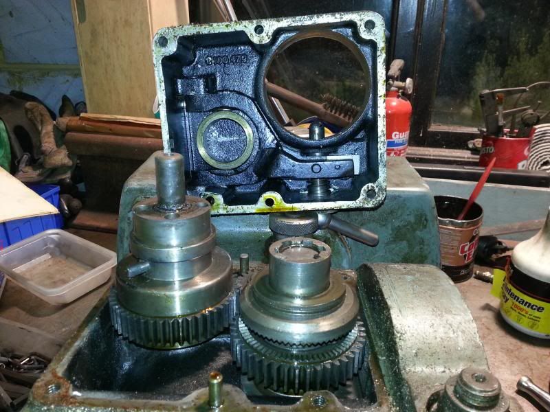
                                    4 bolts undone and casing removed to show quill feed gears

                                    Quill protrusion measured,used when refitting quill,

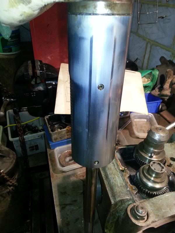
                                    then unwind the quill feed handle and the quill drops out of the head. Doesn't look in bad condition, couple of wear marks but no real grooves.

                                    This is the locking pin for the quill

                                    Cheers,

                                    Paul.


                                    Edited By Paul Major on 09/02/2014 23:04:34

                                    #143374
                                    Paul Major
                                    Participant
                                      @paulmajor25237

                                      With the quill out the next part to remove was the feed gearbox.

                                      Grease, grease and more grease laugh

                                      View down the quill housing

                                      With the quill and gearbx outta the way I turned my attention back to the top part of the head. Remember the brake attachment on the top of the spindle that I couldn't get undone? Turns out it is screwed onto the spindle. With the quill removed I was able to lock the spindle and undo it.

                                      and then pull the bearing off.

                                      I was then able to pull off the top pulley and remove the toothed belt.

                                      Next job was to try and get into the gearbox, easier said than done smile o

                                      Cheers,

                                      Paul.

                                      #144270
                                      Paul Major
                                      Participant
                                        @paulmajor25237

                                        So, not sure if anyone is still reading this, can understand though – its probably not that rivetting just seeing something pulled apart embarrassed.

                                        Anyway, for posterities sake, started to dissassemble the gearbox which as well as transferring drive from the pulleys to the quill, also handles the backgear.

                                        First of removed the back gear lever, note spring that maintains the "detente" position on the lever,

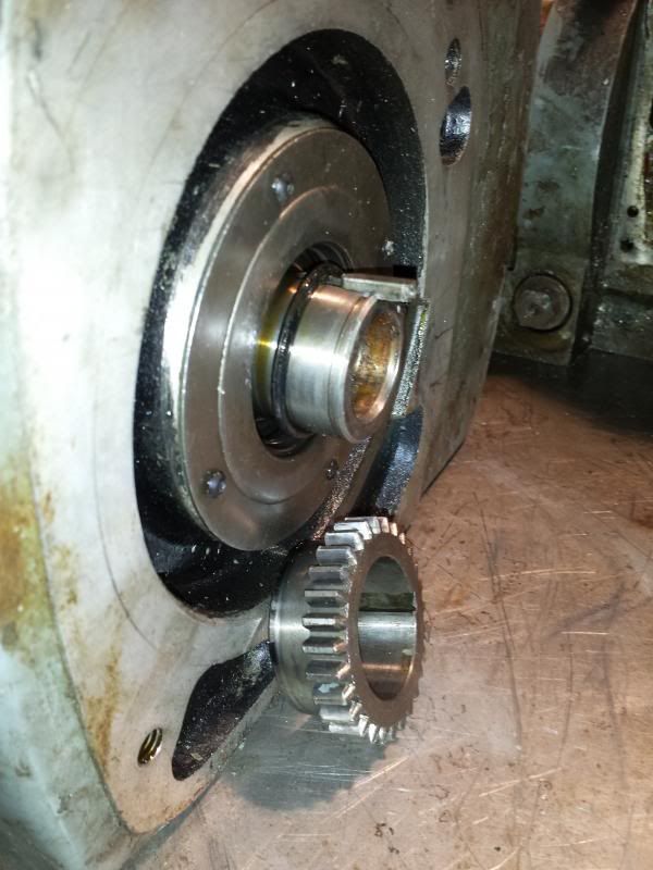
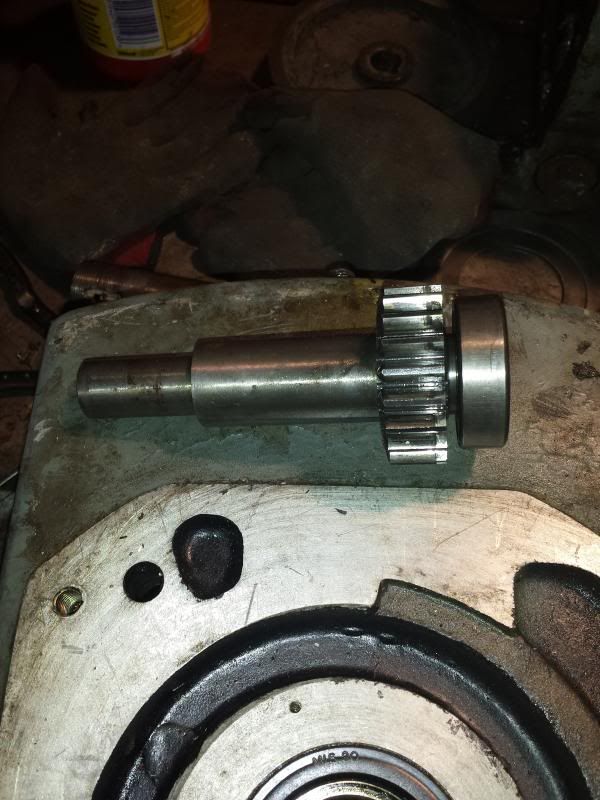
                                        The output shaft of the gearbox has a cog retained with a circlip. Circlip was removed and then a puller used on the gear revealing the woodruff key and rubber o-ring.

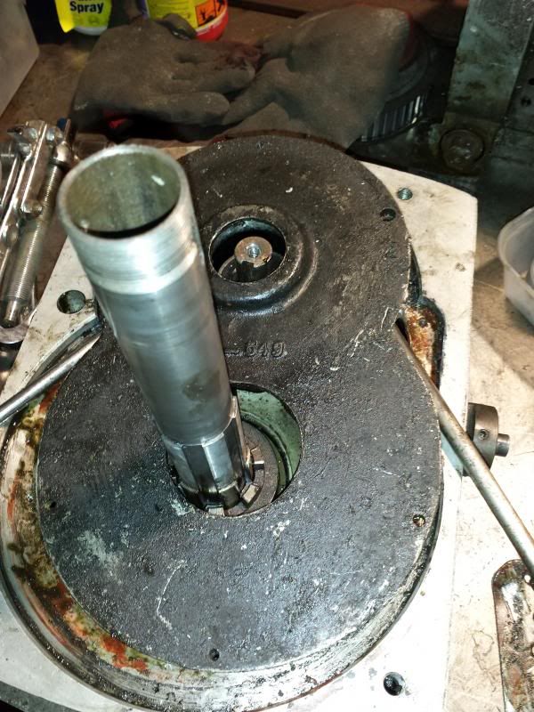
                                        Flipped the 'box and attacked the top. The cover plate is held in by 4 screws but still wouldn't pop off. It turns out the backgear shaft has a bearing on the top end of the shaft which locates in the plate. To get the plate off you have to slide it off this bearing, but without anywhere to locate a puller its a bit of a job.

                                        Eventually levered it off.

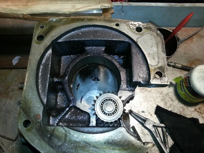
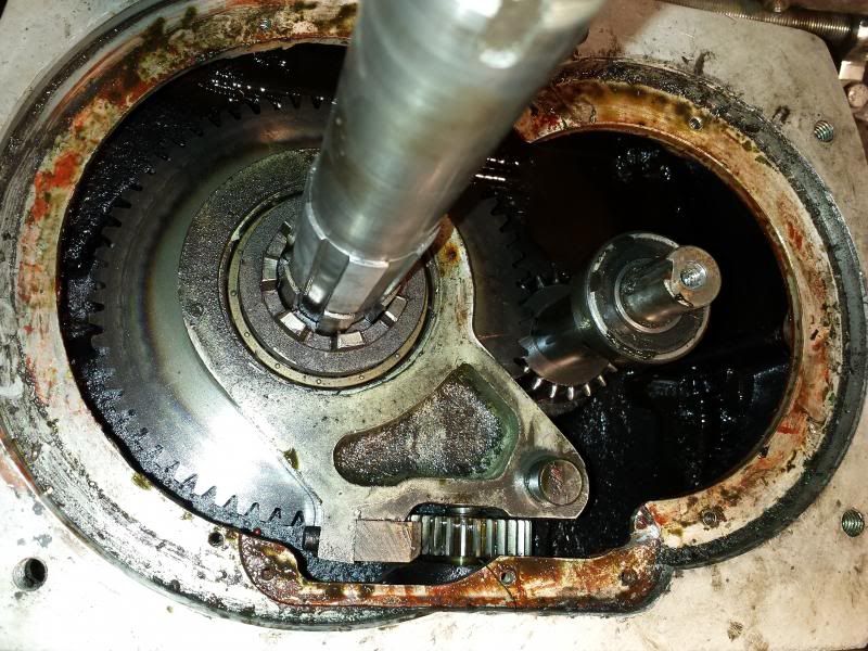
                                        This is the insides of the gearbox, backgear shaft on the right and backgear selector hanging off the main shaft.

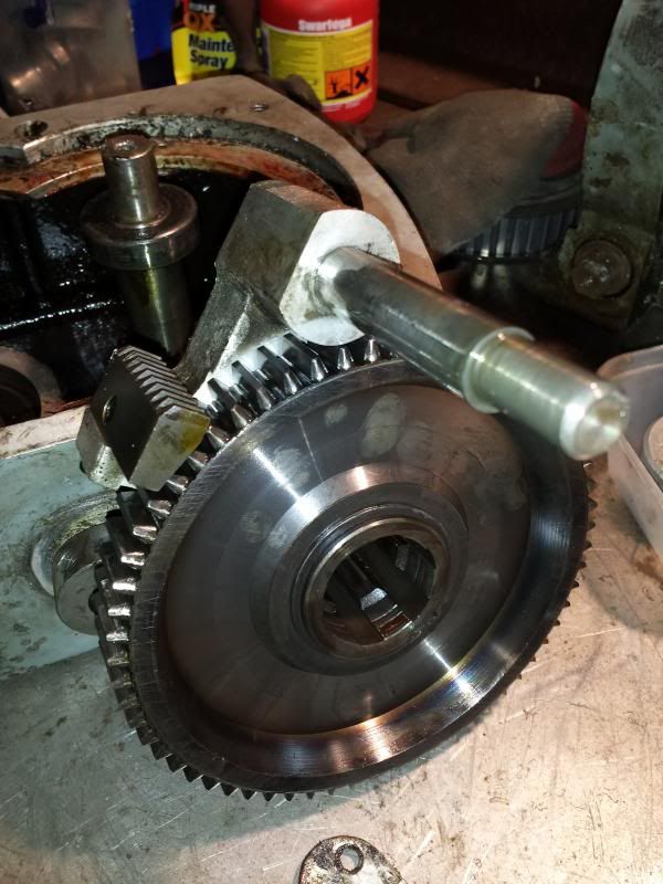
                                        Backgear selector, wheel and clutch slid off the shaft

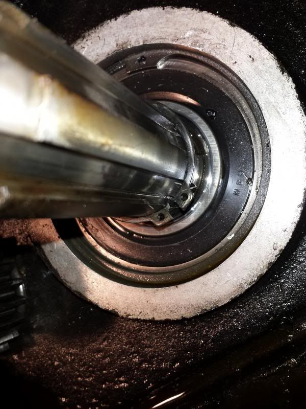
                                        The shaft sits in a large bearing that sits in the bottom of the gearbox covered by a retaining plate on the underside and held in by the large circlip you can see in this picture.

                                        In the above picture you can also see a smaller circlip on the shaft itself, this is why the shaft cannot be withdrawn from the bottom of the gearbox and has to be removed via the procedure described above, i.e. from the top.

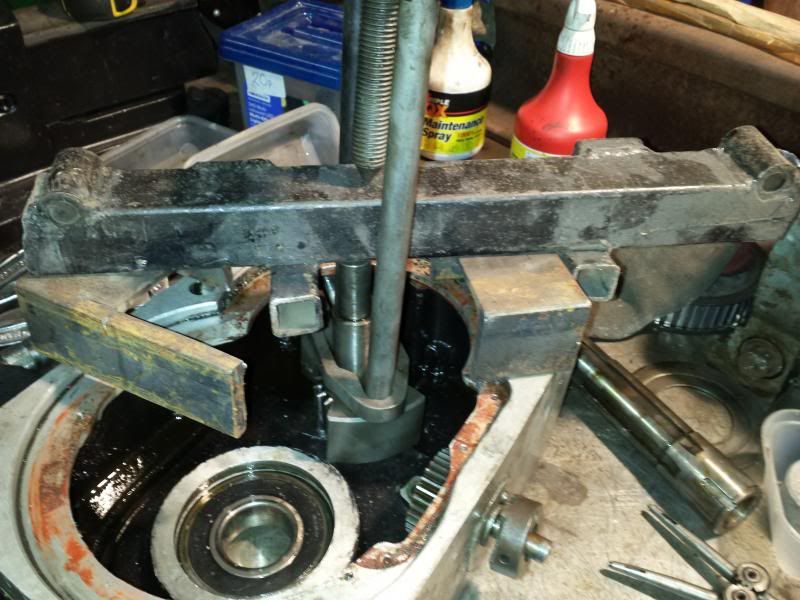
                                        With the main shaft out of the way I could then proceed to remove the backgear shaft. Some improvisation with another gear puller smile o

                                        and the shaft complete with lower bearing comes out.

                                        Next step, pressing out the main bearing and dropping the casing in the solvent tank, unfortunately I got a little bit distracted by purchasing and setting up this wink

                                        Cheers,

                                        Paul.


                                        Edited By Paul Major on 17/02/2014 22:26:41

                                        #144271
                                        Russ B
                                        Participant
                                          @russb

                                          (I'm still with you Paul cheeky)

                                          #144293
                                          Paul Major
                                          Participant
                                            @paulmajor25237

                                            Thanks Russwink

                                            #145678
                                            Harry Souders
                                            Participant
                                              @harrysouders

                                              Hi Paul,

                                              I signed up just now to post in this thread. I was recently gifted an old Beaver PAL mill, and I've been trying to fix it up for the last month or so. My PAL is the smaller sibling of your VRBP – it's smaller overall, and only has (had) one powered axis. You're doing a great job so far, and I really appreciate all the detailed pictures and descriptions.

                                              I haven't gotten as far as you, but I have started the disassembly and inspection. The good news on my mill is that it doesn't seem like it's been used much. I see very little wear on leadscrews, gears, and other bearing surfaces. But, the bad news is that it looks like the mill was abused when it was used.

                                              Other than the usual cleaning and relubricating, I've discovered the following problems:

                                              • The spindle brake was removed long ago, and some monkeys vice gripped the drive sleeve to change tools.
                                              • The X axis used to be power-fed until a forklift operator tipped the mill on it's side and sheared off the motor mount and bent the X axis leadscrew and handle.
                                              • The collet locating pin inside the spindle has been sheared off. (Further inspection shows that the grease in the spindle is pretty old, and I'll have to press out the bearings out and re-lubricate everything)
                                              • The spline head on the worm shaft that nods the head has been sheared off.

                                              So… there are a number of problems to overcome, but it was a free mill so I can't really complain. Worst case scenario is that I'll learn a lot trying to fix it up. So far, I've taken most of the machine apart into its smaller subassemblies, drilled/reamed the worm shaft to install a 3/4" hex head, and I've straightened the bent X axis leadscrew. My progress has slowed over the last few weeks, as I'm waiting for a gear puller to remove the collar around my Y axis lead screw.

                                              If you have a chance, I'd love to see some shots of the spindle brake assembly, as I may end up fabricating that (it seems like parts and information are virtually nonexistent for the PAL mills). I'm loving the pictures of the mill disassembly – keep em coming. I wish I could help you, but it looks like you're farther than I am, and you already have all the lathes.co.uk info. While our machines aren't exactly the same, please let me know if there's anything I can help you with.

                                              Before I go, a couple questions… Do you find it strange that an English mill has all ANSI screw threads? Are your leadscrews also not hardened? Did your quill return spring also make a very unnerving unwinding noise when you pulled the clutch box? Do you have any ideas on how to retension that guy?

                                              Keep up the good work.

                                              #145968
                                              Daniel Robinson
                                              Participant
                                                @danielrobinson12697

                                                Hi Paul,

                                                I too have just purchased a Beaver VBRP and I’m following your exploits with interest.
                                                I have a clean and working model so if you’re looking for any photos as to how to put it back together again or how the wiring should be arranged then give me a shout.

                                                I also have a couple of manuals, one of which was made available by Russ the other is a user manual of 102 pages which I can add to a down load site or email you.

                                                I purchased a 7.5kw 220 single phase – 220 three phase inverter from china for £250 to run the massive motor on the head which, if memory serves is 3kws – 4HP with an ample head room for starting spikes.

                                                Another slide show of someone converting their Beaver to CNC can be found here: http://petensneak.com/zenphoto/beaver-milling-machine/01.jpg.php

                                                Keep up the photos as I am watching with interest.

                                                Dan

                                                #146345
                                                Harry Souders
                                                Participant
                                                  @harrysouders

                                                  Hey Dan… I don't suppose I could convince you to post a couple photos of the spindle brake assembly on your mill? Also, I'd love a copy of the user manual….

                                                  Any chance I could convince you?

                                                  #146373
                                                  Paul Major
                                                  Participant
                                                    @paulmajor25237

                                                    Hey Harry/Dan some other Beavers – whoohoo yes

                                                    I found very sporadic information on these when i started this journey despite many comments saying these mills were much better then the morw popular Bridgeport. Thats why I started this thread as I hoped it would attract/act as a resource for future Beaver owners.

                                                    On the spindle brake, I will go take a few photos later today hopefully.

                                                    I haven't actually checked what threads are on mine yet, doesn't matter when all younare doing is taking them apart laugh

                                                    Not sure if the leadscrews are hardened, how would you check?

                                                    The user manual I have is about 55 pages, if your is 100 pages then it would be great if you could post up as it will increase the general,pool of info.

                                                    Been busy withnwork last few weeks so haven't had a chance to progress the build but will try and add some more stuff this weekend.

                                                    Cheers,

                                                    Paul.

                                                    #146461
                                                    Paul Major
                                                    Participant
                                                      @paulmajor25237

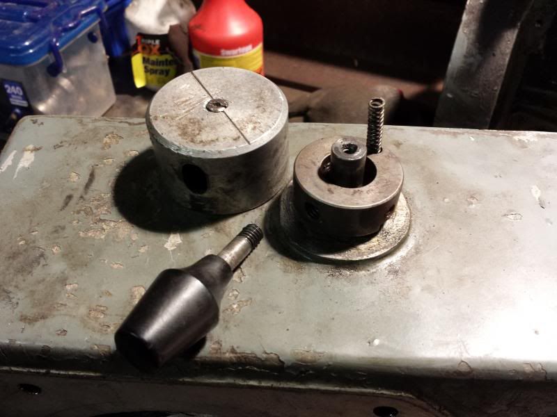
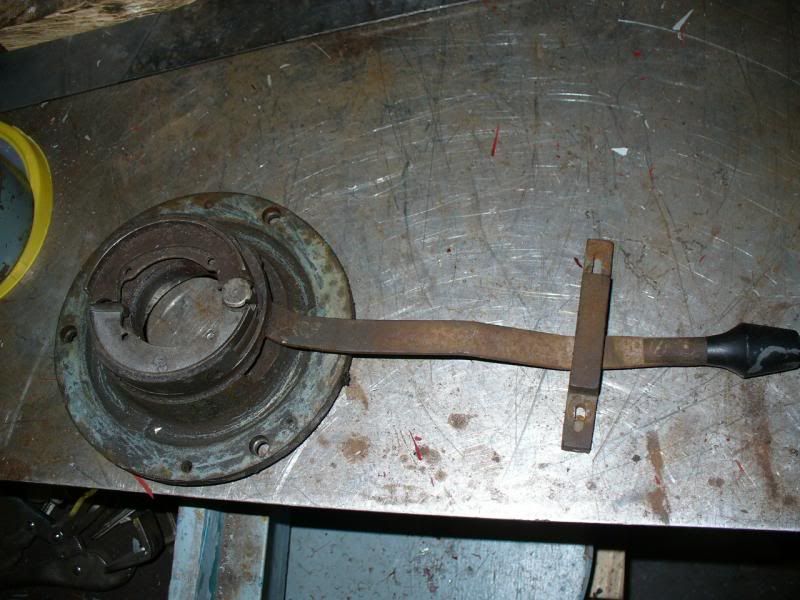
                                                      Hey Harry, info on spindle brake as promised.

                                                      The brake sits on top of the pulley housing and acts on the top of the spindle.

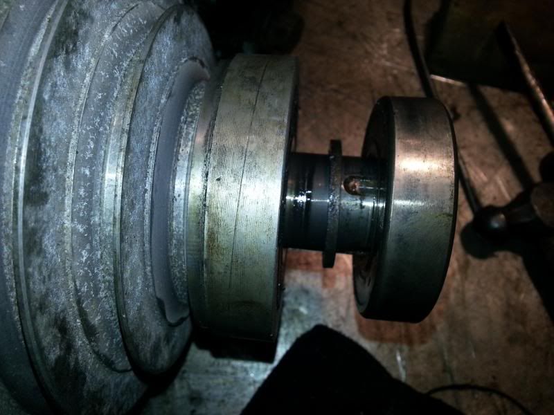
                                                      The lever operates a set of expanding shoes via a cam on the end of the lever

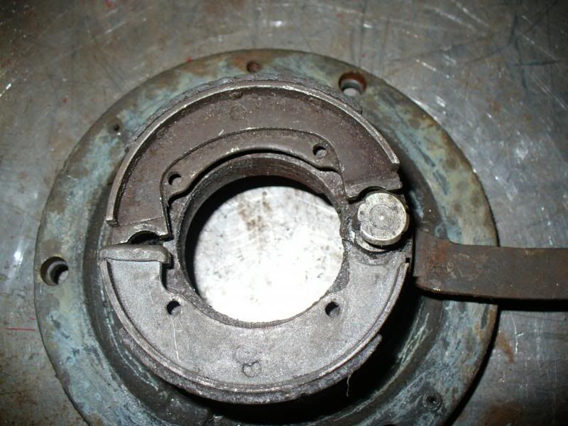
                                                      The brake shoes act on the inside of a drum

                                                      and when it is all assembled the drum sits kinda like this

                                                      So the drum is locked to the spindle and rotates and when the lever is pushed over the shoes expand onto the drum and hence brake the spindle.

                                                      Hope that makes sense

                                                      Cheers,

                                                      Paul.


                                                      Edited By Paul Major on 08/03/2014 21:22:38

                                                    Viewing 25 posts - 26 through 50 (of 182 total)
                                                    • Please log in to reply to this topic. Registering is free and easy using the links on the menu at the top of this page.

                                                    Advert

                                                    Latest Replies

                                                    Home Forums Manual machine tools Topics

                                                    Viewing 25 topics - 1 through 25 (of 25 total)
                                                    Viewing 25 topics - 1 through 25 (of 25 total)

                                                    View full reply list.

                                                    Advert

                                                    Newsletter Sign-up