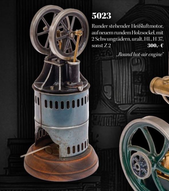
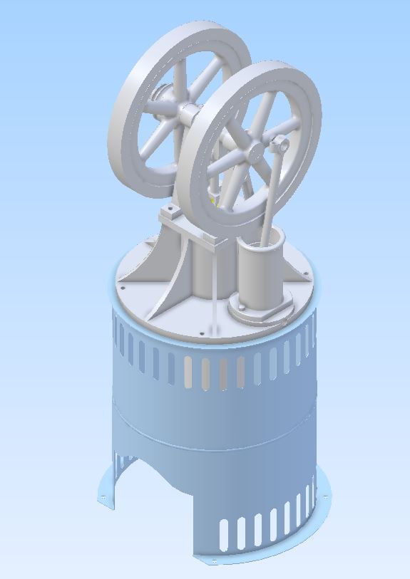
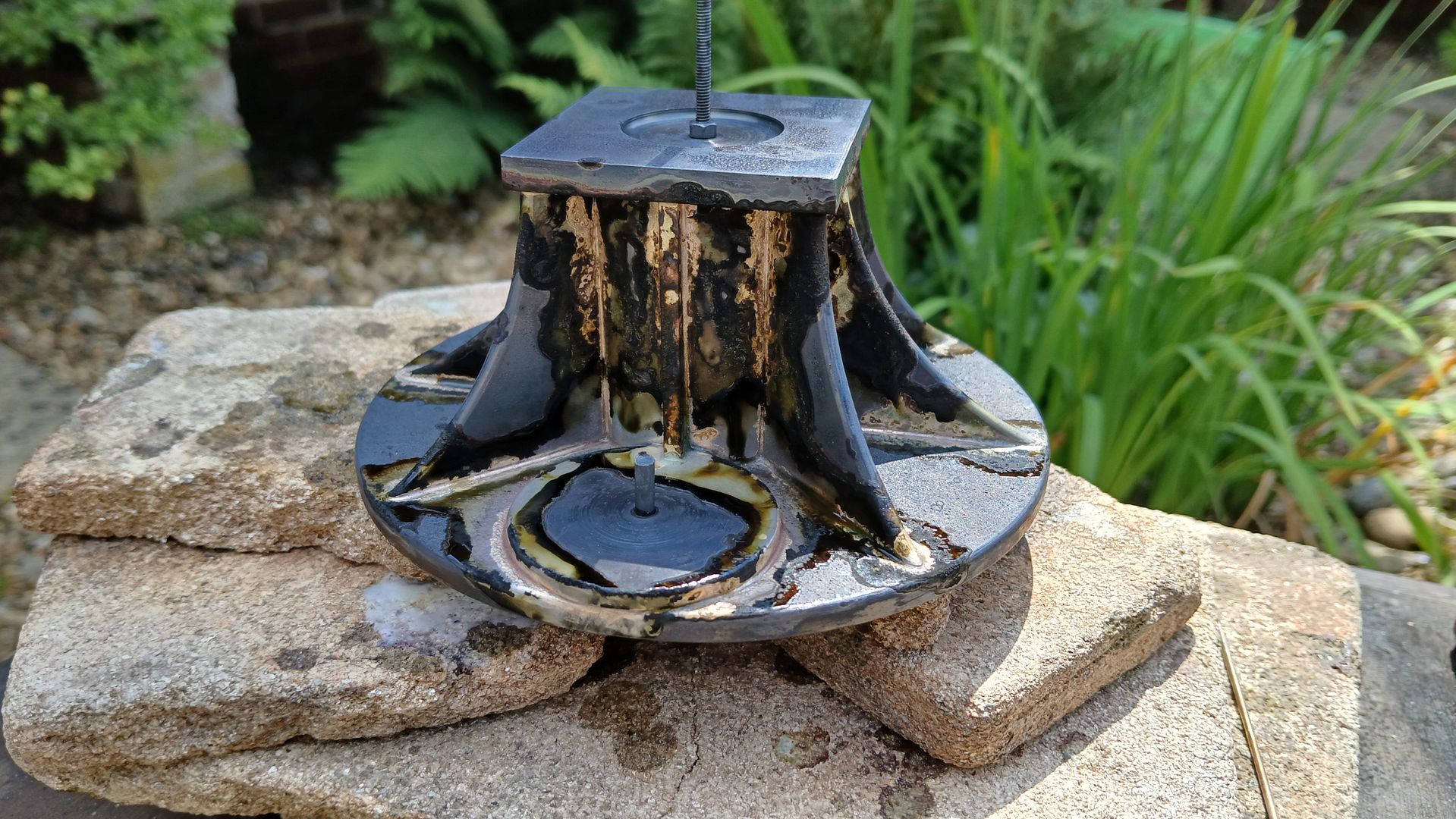
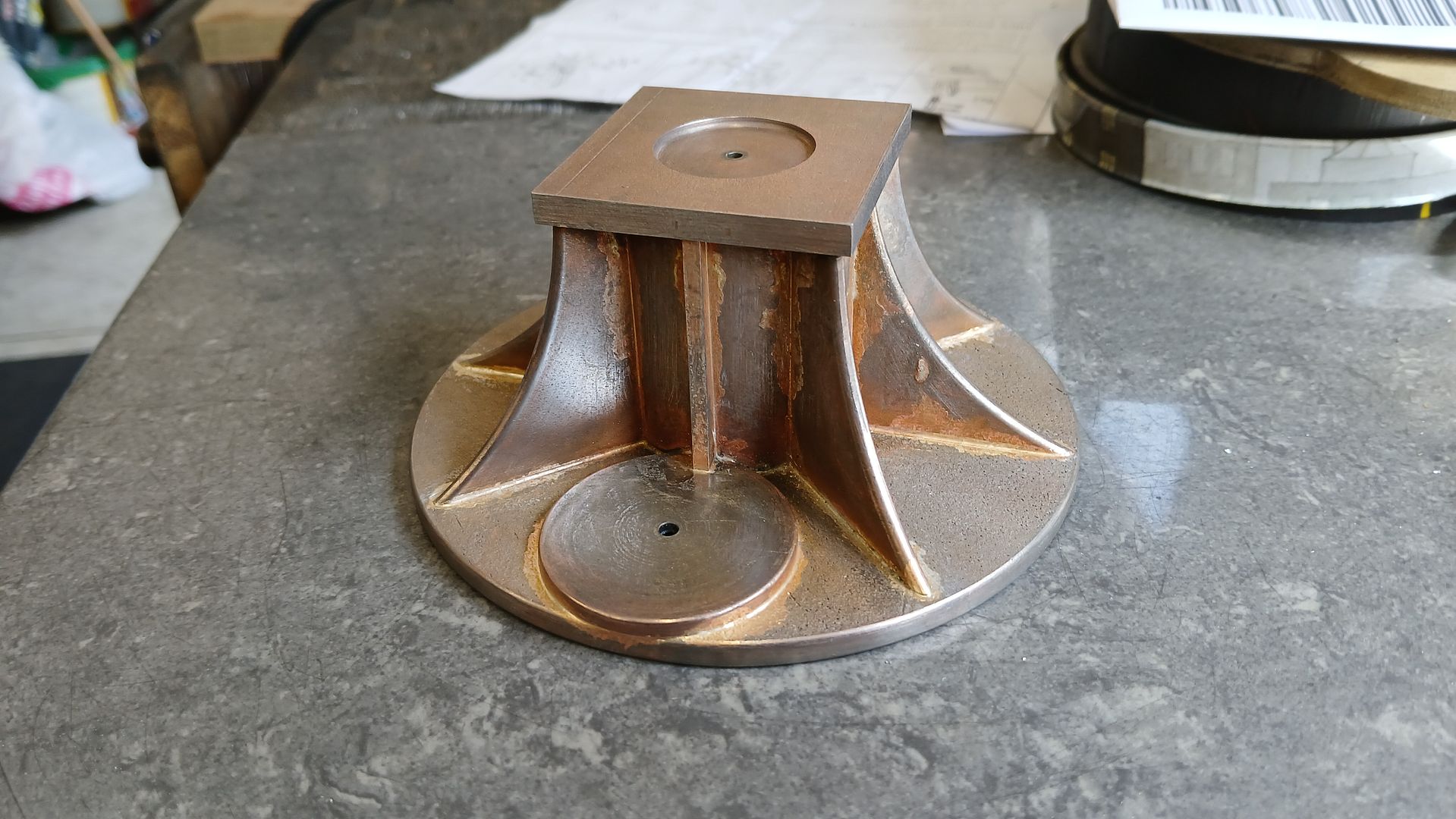
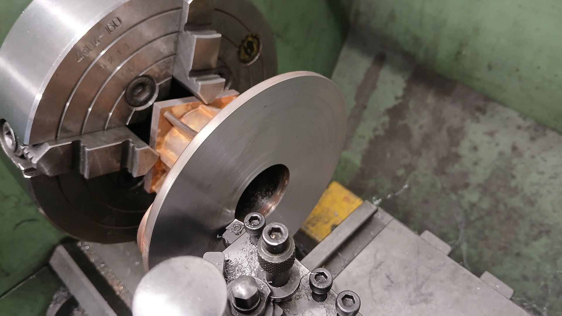
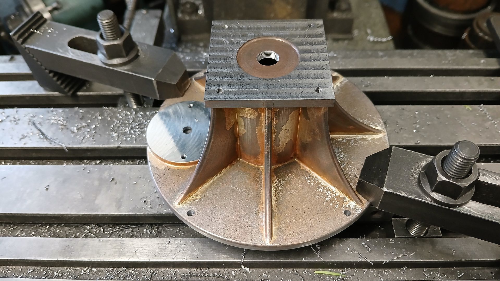
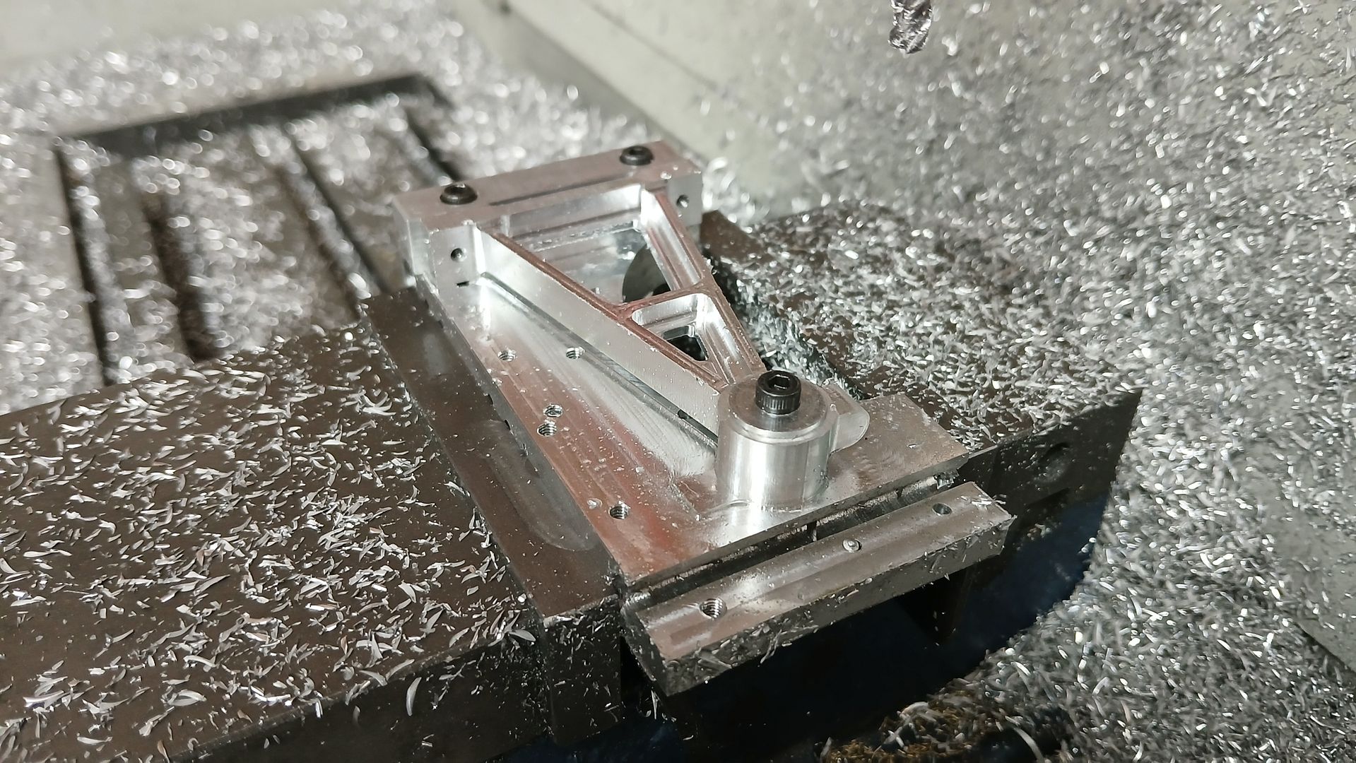
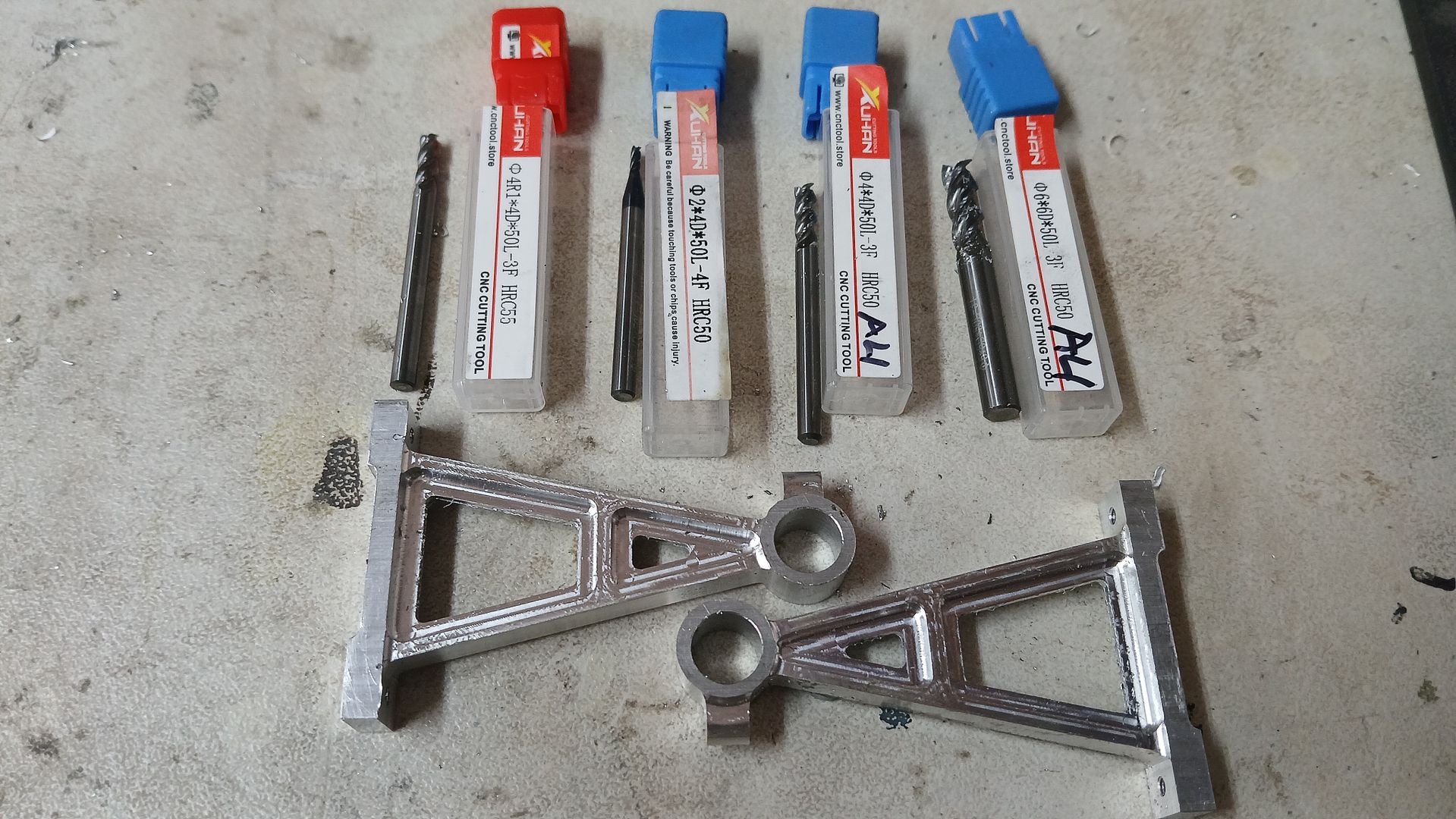
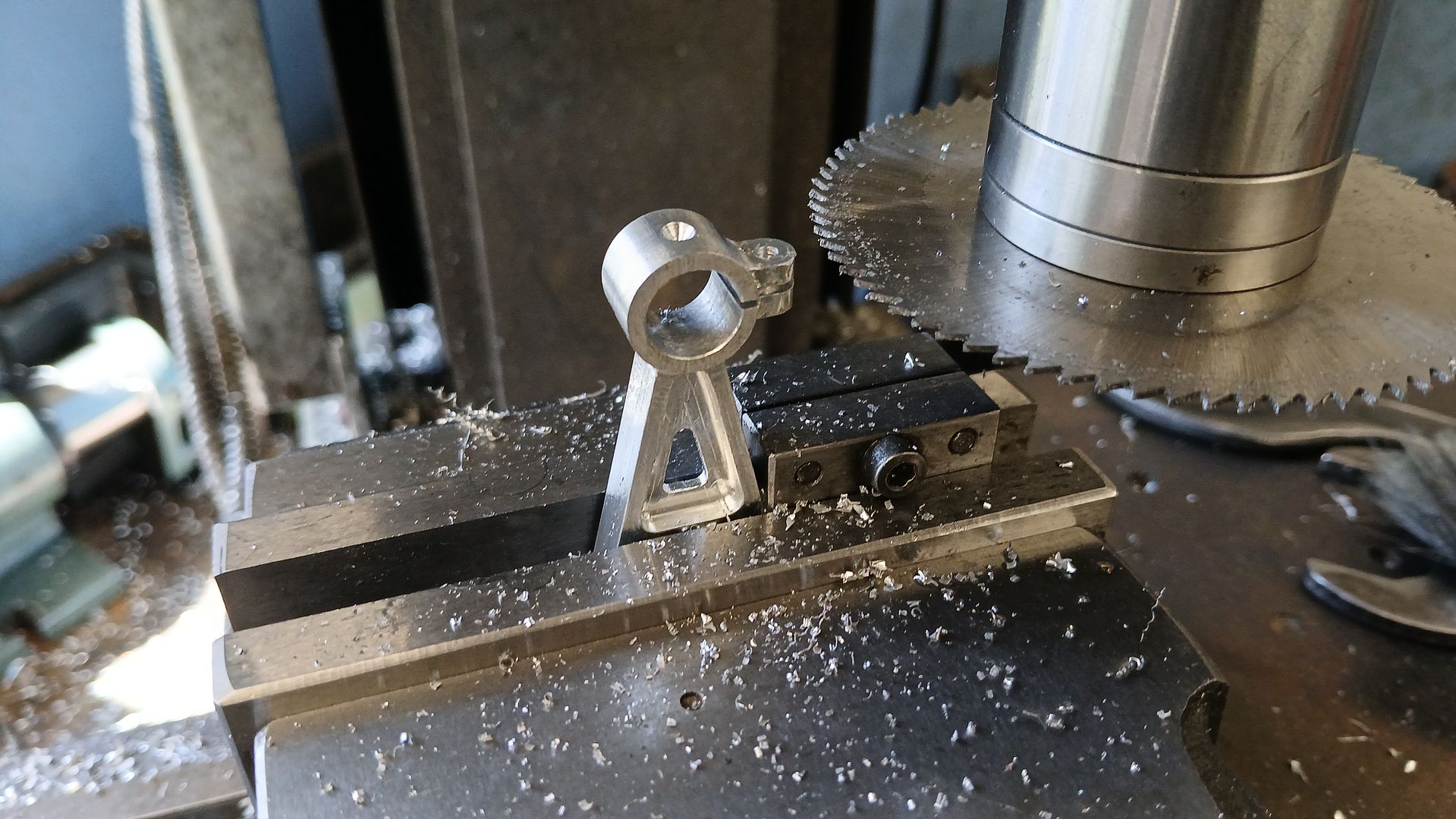
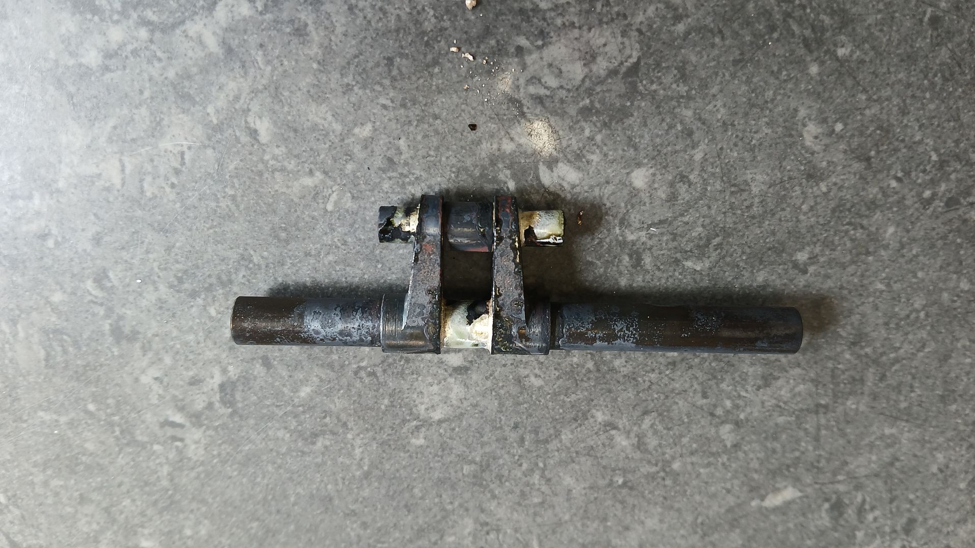
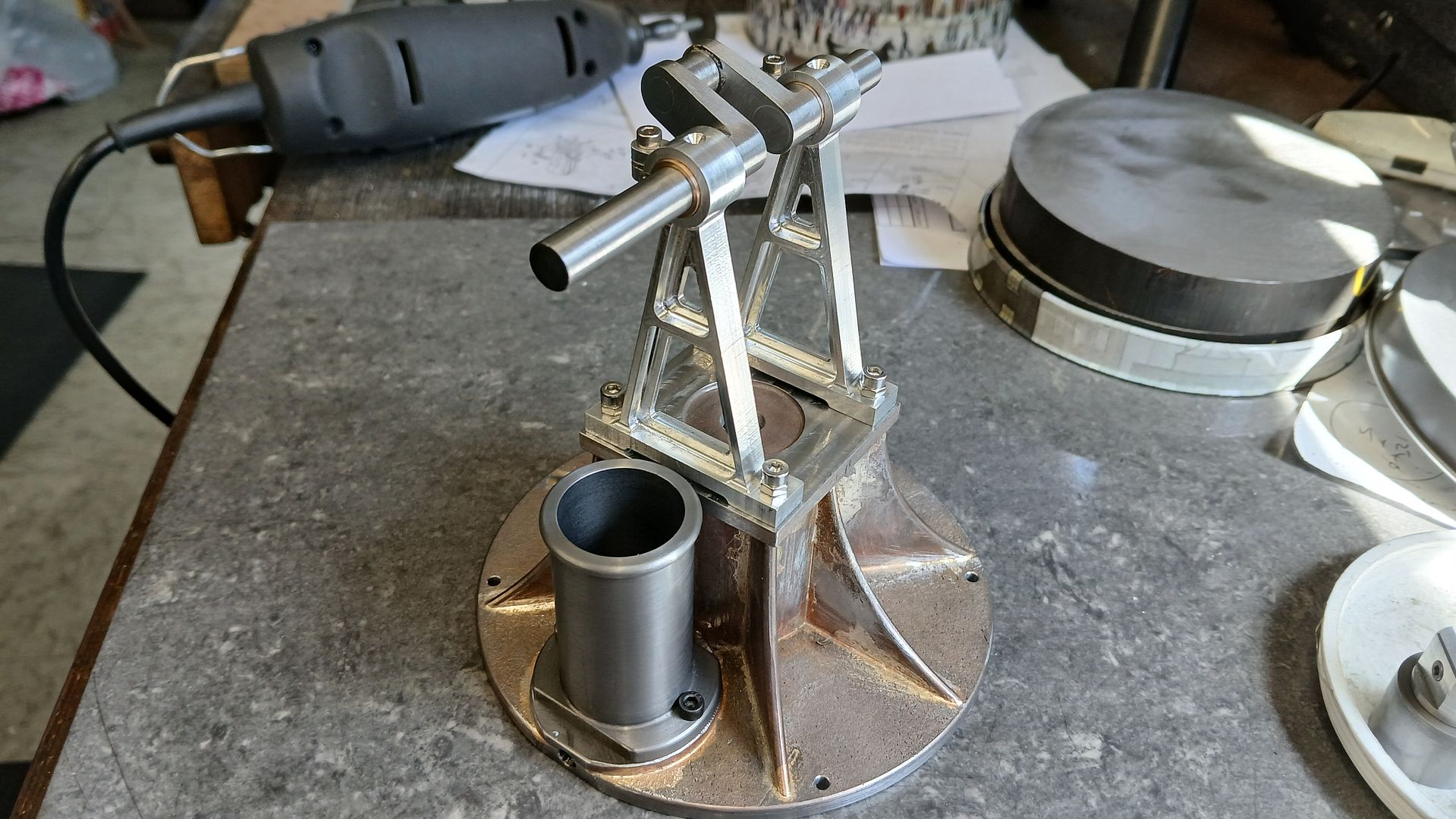
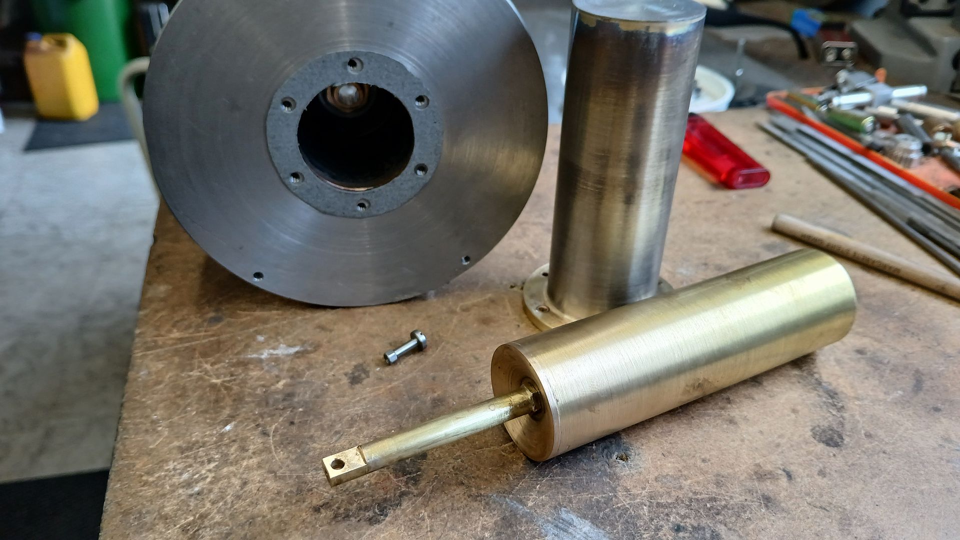
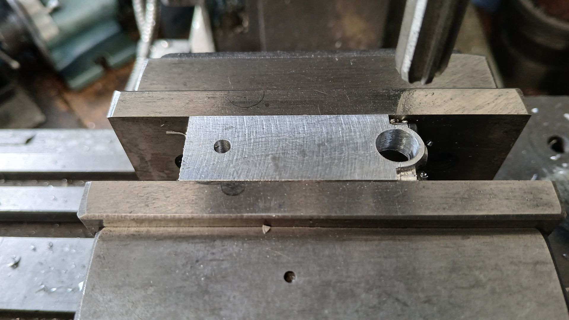
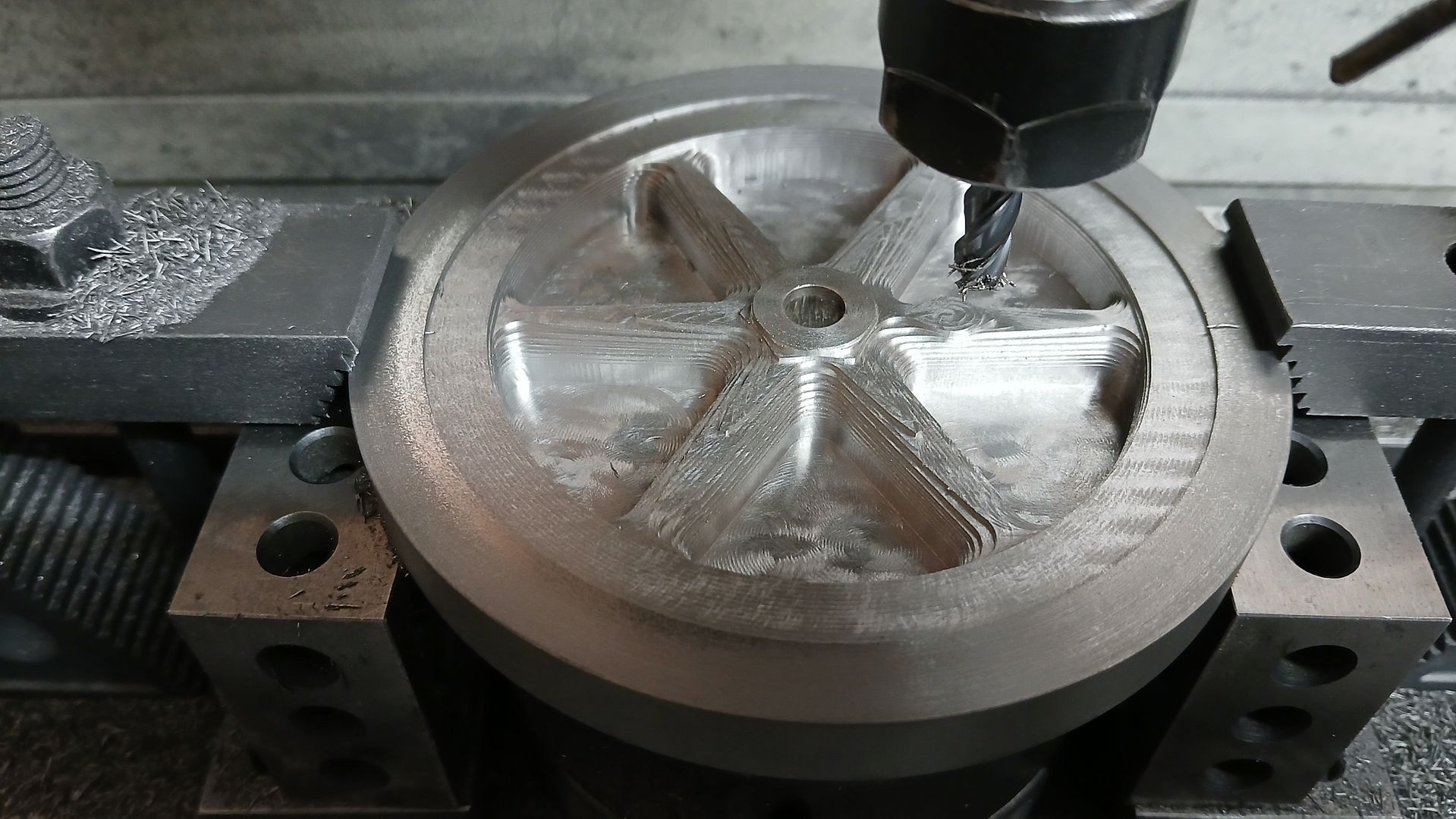
Raab Style Heibluftmotor
Raab Style Heibluftmotor
- This topic has 7 replies, 3 voices, and was last updated 6 September 2025 at 18:57 by
 JasonB.
- Please log in to reply to this topic. Registering is free and easy using the links on the menu at the top of this page.
Latest Replies
-
- Topic
- Voices
- Last Post
-
-
Raab Style Heibluftmotor
Started by:
JasonB
in: Miscellaneous models
- 3
-
6 September 2025 at 18:57
JasonB
-
Hi i have just received 2 lathe’s
Started by:
jjkfj390v
in: Introduce Yourself – New members start here!
- 5
-
6 September 2025 at 17:38
Bazyle
-
My week this week! My workshop videos
1
2
…
11
12
Started by:
Phil Whitley
in: The Tea Room
- 16
-
6 September 2025 at 16:26
Phil Whitley
-
3 phase car lift to single phase
Started by:
glynboy12
in: Beginners questions
- 4
-
6 September 2025 at 16:23
not done it yet
-
Raw Materials
Started by:
Vic
in: Materials
- 2
-
6 September 2025 at 16:02
Vic
-
Mysterious inserts
Started by:
Michael Gilligan
in: General Questions
- 11
-
6 September 2025 at 14:58
bernard towers
-
Motorcycles
Started by:
Richard Simpson
in: Related Hobbies including Vehicle Restoration
- 2
-
6 September 2025 at 11:44
Richard Simpson
-
24cc DIESEL ENGINE FROM SOLID
1
2
Started by:
dean clarke 2
in: I/C Engines
- 11
-
6 September 2025 at 10:35
noel shelley
-
Looking for a quality pencil sharpener
Started by:
Greensands
in: The Tea Room
- 15
-
6 September 2025 at 08:35
Richard Simpson
-
More Fun with Castings – NOT
Started by:
JasonB
in: Materials
- 5
-
6 September 2025 at 06:53
JasonB
-
New member
Started by:
Byron Williams
in: Introduce Yourself – New members start here!
- 3
-
5 September 2025 at 22:56
Bazyle
-
No more Google
Started by:
Vic
in: The Tea Room
- 8
-
5 September 2025 at 22:45
Vic
-
New here
Started by:
jim1978
in: Introduce Yourself – New members start here!
- 2
-
5 September 2025 at 21:19
noel shelley
-
New Member
Started by:
daves 1
in: Introduce Yourself – New members start here!
- 5
-
5 September 2025 at 19:47
zach
-
An Unexpected Message
Started by:
Michael Gilligan
in: The Tea Room
- 8
-
5 September 2025 at 18:52
Nicholas Farr
-
Swing over bed limitation for flywheels
1
2
Started by:
Steve Huckins
in: General Questions
- 16
-
5 September 2025 at 18:36
noel shelley
-
Drunk driver broke my workshop!
1
2
Started by:
stew 1
in: The Tea Room
- 22
-
5 September 2025 at 18:19
Oldiron
-
What Did You Do Today 2025
1
2
…
9
10
Started by:
JasonB
in: The Tea Room
- 38
-
5 September 2025 at 17:37
Dalboy
-
Looking for book on basic strengthening and design methods for steel structures
Started by:
ell81
in: Books
- 12
-
5 September 2025 at 15:36
densleigh
-
Exeter & District Model Engineers Show – 7 Sept
Started by:
Bazyle
in: Exhibitions, Shows and Club Events
- 1
-
5 September 2025 at 10:26
Bazyle
-
Dead Centres?
Started by:
Bo’sun
in: Workshop Tools and Tooling
- 9
-
5 September 2025 at 10:06
cogdobbler
-
Play on warco mini lathe saddle
Started by:
Michael Callaghan
in: Manual machine tools
- 5
-
5 September 2025 at 00:12
samuel heywood
-
Arc’s 25mm indexable end mills…
Started by:
gerry madden
in: General Questions
- 12
-
4 September 2025 at 23:46
samuel heywood
-
Pre-Setting 4-Jaw Chucks Hack for Quick Centering
Started by:
dbwjbp
in: Workshop Techniques
- 16
-
4 September 2025 at 23:16
samuel heywood
-
Parting off on a mini lathe
1
2
Started by:
Andy Brocklehurst
in: Beginners questions
- 23
-
4 September 2025 at 23:03
samuel heywood
-
Raab Style Heibluftmotor


