Quality Problems With the Sieg sx2.7

Advert

Quality Problems With the Sieg sx2.7

Home Forums Manual machine tools Quality Problems With the Sieg sx2.7

Viewing 25 posts - 26 through 50 (of 76 total)
  • Author
    Posts
  • #498007
    Vic
    Participant
      @vic

      I wouldn’t be happy with the damage to the cover. There’s also signs of rust and other badly prepared paintwork. If Sieg really have sent that out of the factory like that they don’t deserve the business. I do wonder however if this machine has been damaged in transit and been tarted up (badly) by the dealer or someone else? Perhaps you’re not the first owner. It would be interesting to know the date of manufacture. This doesn’t necessarily effect the standard to which it’s been manufactured, maybe they’re all like this. I can’t comment on your methodology except to say using a square in one of your setups wouldn’t be my first choice. I wonder what other dealers of similar machines think of your findings and what they’d be prepared to do about it? Good luck with the machine whatever you decide to do but be aware there are plenty of folks out there that have “fettled’ these type of machines to improve them. Looking on the net should give you some idea if you decide on that route.

      Advert
      #498010
      Dave Halford
      Participant
        @davehalford22513

        I can leave it this way and ignore the fact that I have a play in the head of 0.2 mm which I can not fix since the gib will not go any further and if it did I will lose even more travel of the head (at the top) and I will have to live with the fact that the quill is not parallel to the head.

        If this was an old style gib with screws every 50mm to adjust the play, then being tight at one end would imply the wrong adjustment and would possibly tilt the head.

        Don't wedge gibs require equal adjustment at each end?

        #498152
        Nir Somthing
        Participant
          @nirsomthing67828

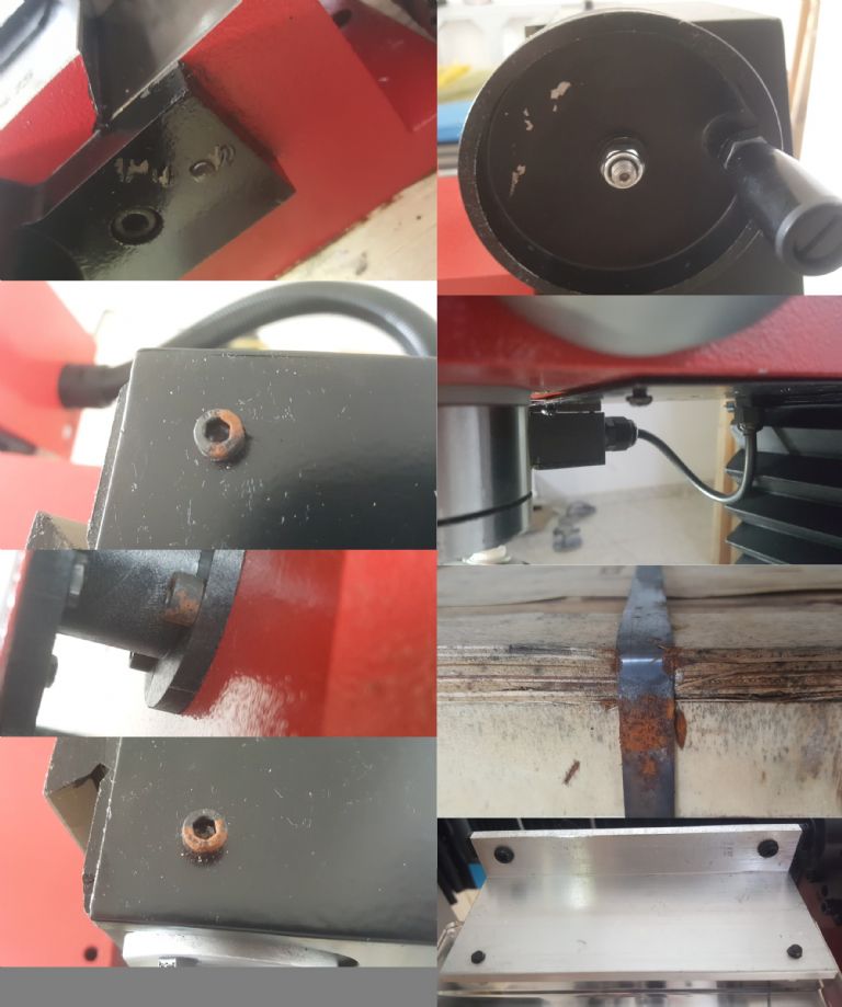
          Ok, So I noticed from the previous results of the head movement (that I shared here), that the maximum deviation is in the middle of the column. So I thought maybe I will adjust the gib at that height and see what the results will be. I found out that even if I take the gib all the way down such that the counter screw only holds by one turn (obviously if I will lock it tight I will damage it’s thread) that the head still move by 0.27 mm (it was 0.275mm before) and that now I cannot move the head all the way up by 10 cm, in the picture you can also see the cover shear that I talked about covered in paint. I found someone else here in this forum that also talked about this problem, Piotr, luckily I can still get (hopefully) service from my dealer.

          Adjusting Gib again.jpg

          Dave Halford, the old style gib is somewhat flexible compared to the new style, however it’s purpose is the same. there is not much of a different between them, so long as all the parts are properly machined. As I see it, and please tell me if I am wrong, the gib’s only job is to lower the play between the column (bed) and the head (saddle?) of the mill and the more you tight it up the harder it will become to move the head and the wear of all parts involved will increase. In my case since the column (bed) has a trapezoidal shape (wider in the top, thinner in the bottom) both styles will not have helped. The way you adjust the new style (if you want to tighten it up) is by releasing the bolt at the top half a turn, then releasing the bolt at the bottom half a turn, and then locking the top bolt against the bottom one full turn. If there was only on bolt at the top then when the head was moved upwards the gib will have tighten itself while moving downwards and the head would not move.

          I also decided to share with you a few more pictures from the first mill I got, so that others may take it into account before buying. The shipping Is by the sea, so obviously high humidity and a lot of salt, you can see in the picture the rust on the box metal strips, and there was no silica gel bag inside. So no wonder the paint peeled off and the screws got rusted, it will probably affect the electronics in the long run.

          First mill.jpg

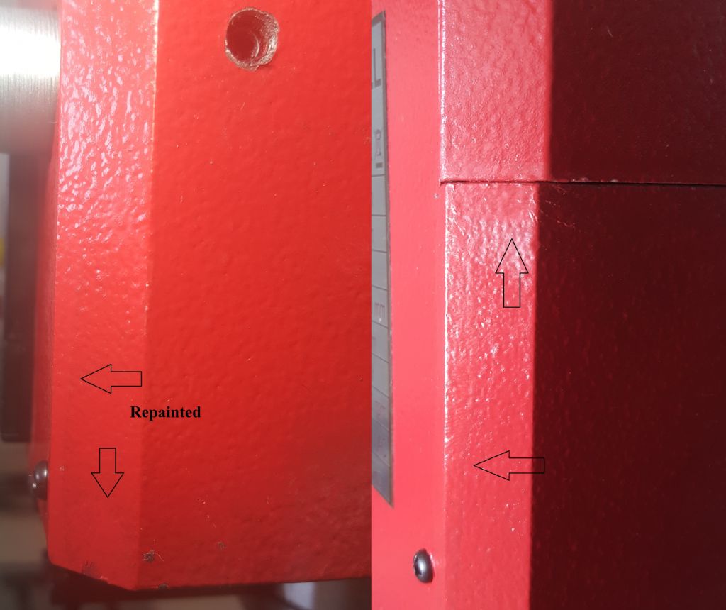
          Vic, thank you, I totally agree, which method would you have used? I learned it from the internet… About the mill, it is 100% Sieg fault. The dealer ordered 12 machines (There is a sticker on the box) and when he shipped me the first mill it was after waiting for it to arrive, so it was sent to me directly from the harbor not from his store, and the number embedded on the base was 90415 and after he sent me a replacement, the mill was stamp with the number 90414, so there is no chance he did it. I think that, as SillyOldDuffer mentioned, Sieg don’t put the machines for Quality Assurance (even if I have a triangle piece of paper that says so) when a dealer orders a full container. Maybe they are counting on the name of the brand? Or maybe they haven’t renewed the manufacturing line after producing 100k machines? I have no idea, but I am truly disappointed. I can tell however that the new mill was painted twice, it is very hard to see depending on your monitor, but they have repainted the front with a slightly different tone, the camera doesn't catch it but the eye certainly does…

          Repainted.jpg

          Thank You,

          Nir

          #498154
          Nir Somthing
          Participant
            @nirsomthing67828

            *** I forgot to mention that:

            https://youtu.be/EIcVFVVNnHM

            It’s only a cosmetic, the inside runout is 0.01mm , but when I first saw this, my heart fell off

            #498160
            ChrisB
            Participant
              @chrisb35596

              Hi Nir, rather than worrying too much and loosing time checking the machine, it would be more helpful if you squared up a piece of material and then measured the work piece. This will help you better understand the problem with your mill and to what extent it is. I saw your video up above where you appear to be measuring the mill head tram, with that extension arm swinging from edge to edge of the table you will never get a reliable reading.

              #498192
              Steviegtr
              Participant
                @steviegtr

                Nir i have stayed quiet on this one. But one comment if i may. I have an old UK made Tom Senior vertical mill. When i was tramming the head, i tried various methods. Using a Jacobs chuck with a swing rod just like you have done. It was miles out. I then used another quality Albrecht hand tighten chuck. Both were a long way out. I ended up using a 22mm MT2 Facemill arbor of chinese origin, but with a DTI was found to be very accurate. I then bolted this to the swing bar. My bed is 720mm long so quite a range from end to end. With this & very careful use of a rubber mallet got the Tram pretty much perfect. I think it was Jason B who told me that using a chuck is not going to be accurate.

                I also had problems with a precision square set. There were 4 different sizes in a lovely wooden box, bought new. Not one of the squares is accurate. Luckily someone recently gave me an old Rabone Chesterman steel set square, which is ancient but very accurate.

                With all your other problems i do sympathise with you & hope with some effort you may get the Mill as you would like it to be. It sounds like where you are in the world that machinery is very expensive.

                Regards. Steve.

                #498242
                Tony Pratt 1
                Participant
                  @tonypratt1

                  Steve, if you understand tramming you will realise it doesn't matter how the swing rod is held [chuck/collet etc.etc] as long as the set up is rigid & the DTI used is repeatable the results will be reliable.

                  Tony

                  #498245
                  ChrisB
                  Participant
                    @chrisb35596
                    Posted by Tony Pratt 1 on 28/09/2020 08:26:33:

                    Steve, if you understand tramming you will realise it doesn't matter how the swing rod is held [chuck/collet etc.etc] as long as the set up is rigid & the DTI used is repeatable the results will be reliable.

                    Tony

                    A chuck's radial runout should not make any difference in the tram readings, but if there's any angular runout (wobble) in the chuck jaws you will get errors, especially when using a swing rod the size the OP is using. He should measure over a shorter range imo. That rod's length is amplifying any misalignment the head may have. I would be much more realistic is he faces and squares off a piece of material and then measure it. Most probably the OP will find it is within his precision expectations.

                    I had similar issues with my WM18 when I first bought it, but soon found out that it's useless chasing decimals without taking some cuts to reference with.

                    #498246
                    Michael Gilligan
                    Participant
                      @michaelgilligan61133
                      Posted by Tony Pratt 1 on 28/09/2020 08:26:33:

                      Steve, if you understand tramming you will realise it doesn't matter how the swing rod is held [chuck/collet etc.etc] as long as the set up is rigid & the DTI used is repeatable the results will be reliable.

                      Tony

                      .

                      That should start an interesting discussion angel

                      MichaelG.

                      .

                      Edit: and I see it already has

                      Edited By Michael Gilligan on 28/09/2020 08:54:08

                      #498250
                      Tony Pratt 1
                      Participant
                        @tonypratt1

                        Chris, I totally disagree, whatever holding method is used will present the DTI probe in the same relative position to the table as long as the set up is rigid, furthermore you are better off using a longer arm to amplify the head error so when you get it 'close enough' at that large radius it will be completely acceptable at say face mill diameters of 50/60/70 mm. If you use a block to check squareness you are then possibly introducing a vice error.

                        Tony

                        #498251
                        Emgee
                        Participant
                          @emgee

                          ChrisB stated: A chuck's radial runout should not make any difference in the tram readings, but if there's any angular runout (wobble) in the chuck jaws you will get errors, especially when using a swing rod the size the OP is using.

                          I agree with this so if there is any runout measured with a DTI it needs to be established if it is radial or angular, if radial then using the longer bar will magnify any tramming error.

                          If angular rotate the chuck so the high/low points are aligned in the Y axis and set the bar along the X axis, this will allow some readings to be taken that will give an idea to the amount of lean over of the head/spindle.

                          Emgee

                          #498252
                          Michael Gilligan
                          Participant
                            @michaelgilligan61133
                            Posted by Tony Pratt 1 on 28/09/2020 09:59:32:

                            Chris, I totally disagree, whatever holding method is used will present the DTI probe in the same relative position to the table as long as the set up is rigid […]

                            .

                            Sorry, Tony …

                            It’s simple trigonometry : If there is an angular error between the ‘output axis’ of the chuck and the axis of the machine spindle, then your trammel beam will act like a swash plate and the DTI will rise and fall.

                            MichaelG.

                            .

                            Edit: Swash Plate animation: https://youtu.be/z-wA9Tx8930

                            Edited By Michael Gilligan on 28/09/2020 10:23:21

                            #498256
                            Tony Pratt 1
                            Participant
                              @tonypratt1

                              Nothing to do with trigonometry, say the DTI is at 0 degreees on the LH side of the table, you then rotate the spindle 180 degrees to the RH side of the table the DTI will be in the same space in both positions, the chuck/collet or whatever is only really connecting the DTI to the spindle bearings in a rigid set up. Difficult to explain in words which make sense?

                              Tony

                              #498259
                              Vic
                              Participant
                                @vic

                                Like others I tram my mill by holding a bar with a dial gauge mounted on it in a chuck.* I’m not sure though how I’d actually check a machine but as others have said using a square on the table as pictured earlier isn’t a method I’d trust. I’d probably use a mandrel directly in the quill and take measurements from that somehow.

                                * When I asked an old time served machinist how to do it he said it could be done with just a bent rod and a couple of fag papers. I actually did it that way at first and it seemed to work fine judging by the results!

                                #498284
                                ChrisB
                                Participant
                                  @chrisb35596
                                  Posted by Tony Pratt 1 on 28/09/2020 10:35:58:

                                  Nothing to do with trigonometry, say the DTI is at 0 degreees on the LH side of the table, you then rotate the spindle 180 degrees to the RH side of the table the DTI will be in the same space in both positions, the chuck/collet or whatever is only really connecting the DTI to the spindle bearings in a rigid set up. Difficult to explain in words which make sense?

                                  Tony

                                  You're actually right Tony, after thinking about it, it's true any runout will not have any effect as long as the spindle is running true in it's bearings. As you correctly pointed out, with the mill head and spindle perfectly trammed, if the chuck jaws had to have ''x'' amount of radial runout on the LH side of the table, turning it through 180deg to the RH side of the table the runoit will remain the same.

                                  Still, I believe a longer arm will be more unhelpful rather than helpful. I swing the dti at the max depth of the table rather than the length. Why? because I do not need to chase microns. Measuring at the edge of the table will be next to impossible to align the head from my limited experience with this type of mill head. A small tap one way and you're out, another tap the other way and you're out again.

                                  I reason that I will never need to swing a cutter diameter larger than the depth of the table, so if at this diameter the table is flat, that will be enough for me.

                                  editing spelling

                                  Edited By ChrisB on 28/09/2020 13:38:02

                                  #498286
                                  Tony Pratt 1
                                  Participant
                                    @tonypratt1

                                    Chris B, thanks I thought I was right but as you might have imagined I did think it through again. As you say using a long 'arm' is a bit tricky but that's the way I do it, each to their own.

                                    Tony

                                    #498292
                                    Michael Gilligan
                                    Participant
                                      @michaelgilligan61133
                                      Posted by Tony Pratt 1 on 28/09/2020 10:35:58:

                                      … the chuck/collet or whatever is only really connecting the DTI to the spindle bearings in a rigid set up …

                                      .

                                      I apologise, Tony … You were correct in your first assertion.

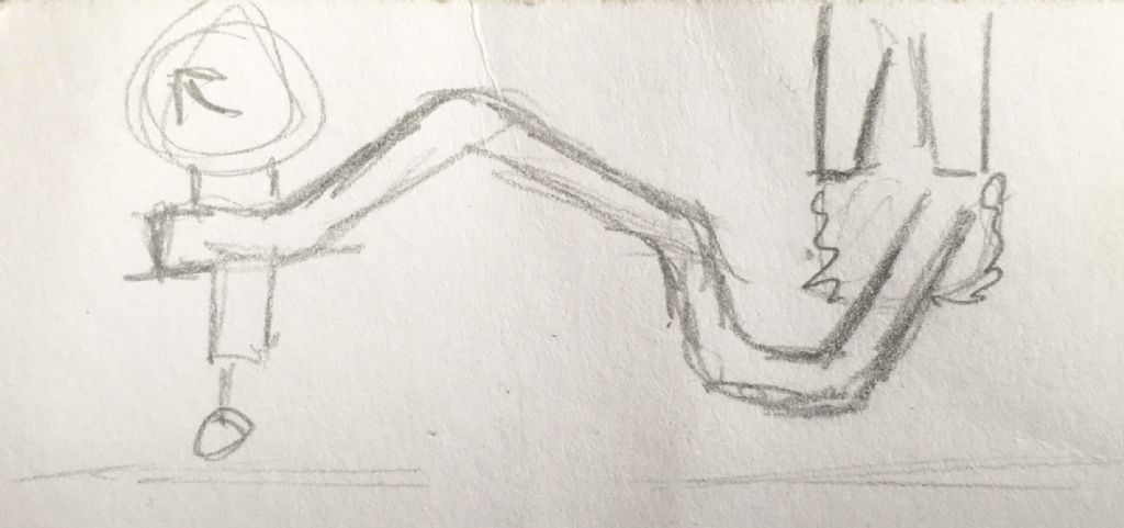
                                      I have just returned from a good long walk, and some pondering; and it became quite clear that the mis-aligned chuck would simply form part of the “any shape you like, provided it’s stiff enough” trammel beam.

                                      By way of demonstration : here is the scrappy little sketch that I doodled whilst I was out.

                                      .

                                      0f6ae261-720a-40d9-99ee-02af2dea90ba.jpeg

                                      .

                                      blush MichaelG.

                                      #498296
                                      Tony Pratt 1
                                      Participant
                                        @tonypratt1

                                        Michael, thanks for the apology, your arguments certainly made me think which is a good thingsmiley

                                        Tony

                                        #498300
                                        Steviegtr
                                        Participant
                                          @steviegtr
                                          Posted by Tony Pratt 1 on 28/09/2020 15:02:22:

                                          Michael, thanks for the apology, your arguments certainly made me think which is a good thingsmiley

                                          Tony

                                          Me too. Sorry as i got it wrong.

                                          Steve.

                                          #498320
                                          Nir Somthing
                                          Participant
                                            @nirsomthing67828

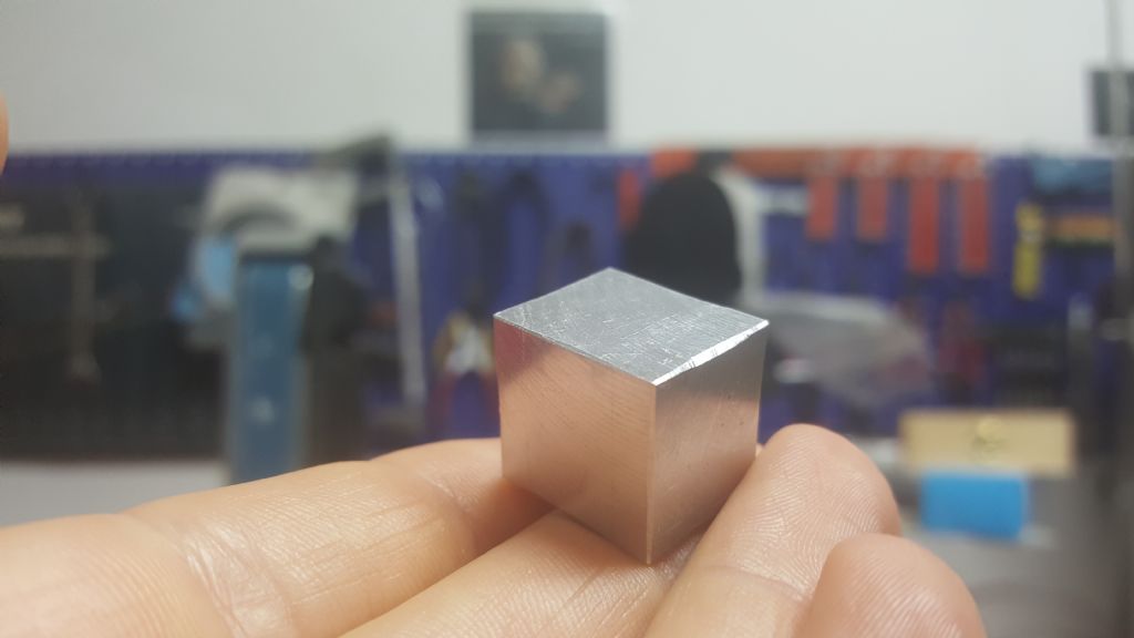
                                            ChrisB & SillyOldDuffer, I thought about your comments about cutting a metal or squaring something, and I honestly don't think this is the way to go, for one, when squaring properly, if my face cutter is tilted 10 degree to the front and I rotate the piece on its axis, it will still turnout to be perfect. even the sides! so long as my x axis is spot on – and ~0.03 mm is spot on. Also, I don't have a big enough stock of material. And My point is that when times comes and I will have a project that will need this few hundreds of accuracy all problems will arise… Will it cut metal? I don't see why not, I already squared a small aluminum piece of 20 mm thick to 18.6×17.4×15.6, but this won't help me judge my mill at all, first of all I don't have a proper grounded granite table and a height gauge, and my machined square and caliper will only give good results as my vise, which is a cheap Wilton vise with an accuracy of doubtedly 0.001". I plan to buy a Kurt 4" vise, and a granite table and so on, but only after I know my mill worth it. ***By squaring I assumed you meant making a cube:

                                            Tiny Cube.jpg
                                            As I said my ER collect didn't arrive yet, so my only choice is to use a square and it is one order more accurate then the measurement I am looking for so I don't see the problem.
                                            Steve, Tony, Michael Emgee & Vic, I knew some people don't agree on using a chuck, so as I mentioned, I disassembled the arm from the chuck after each turn-measurement reading to exclude any error that may arose from tilt of the chuck or any other factors, and I reattached the arm at a different angle relative to the chuck and it gave me the same results every time within 0.006 mm. Regarding the length of the table I agree with Tony, the problem is that this table height wobbles like crazy, and as I see it, the edges are higher than the middle on all corners. So maybe this is not the way to go here.

                                            Anyway does someone has an idea from from what I advised earlier? Thank You.

                                            #498352
                                            Tony Pratt 1
                                            Participant
                                              @tonypratt1
                                              Posted by Steviegtr on 28/09/2020 16:15:01:

                                              Posted by Tony Pratt 1 on 28/09/2020 15:02:22:

                                              Michael, thanks for the apology, your arguments certainly made me think which is a good thingsmiley

                                              Tony

                                              Me too. Sorry as i got it wrong.

                                              Steve.

                                              Absolutely no problem

                                              Tony

                                              #498355
                                              Nicholas Farr
                                              Participant
                                                @nicholasfarr14254

                                                Hi MichaelG, I like your scrappy little sketch. smile

                                                Regards Nick.

                                                #498357
                                                Tony Pratt 1
                                                Participant
                                                  @tonypratt1

                                                  As I said my ER collect didn't arrive yet, so my only choice is to use a square and it is one order more accurate then the measurement I am looking for so I don't see the problem.
                                                  Steve, Tony, Michael Emgee & Vic, I knew some people don't agree on using a chuck, so as I mentioned, I disassembled the arm from the chuck after each turn-measurement reading to exclude any error that may arose from tilt of the chuck or any other factors, and I reattached the arm at a different angle relative to the chuck and it gave me the same results every time within 0.006 mm. Regarding the length of the table I agree with Tony, the problem is that this table height wobbles like crazy, and as I see it, the edges are higher than the middle on all corners. So maybe this is not the way to go here.

                                                  Anyway does someone has an idea from from what I advised earlier? Thank You.

                                                  Mr Nir Somthing, is there anyone you know personally near your location who can advise you? I say this with the best intentions as there are many people on this forum who could evaluate your machine if they had eyes on it but diagnosing a problem via a forum is nigh on impossible, are there any model engineering clubs near you for example or do you know any mechanically biased co workers? Please don't take this as a negative posting.

                                                  Tony

                                                  #498367
                                                  Pete White
                                                  Participant
                                                    @petewhite15172
                                                    Posted by Tony Pratt 1 on 28/09/2020 19:11:19:

                                                    Mr Nir Somthing, is there anyone you know personally near your location who can advise you? I say this with the best intentions as there are many people on this forum who could evaluate your machine if they had eyes on it but diagnosing a problem via a forum is nigh on impossible, are there any model engineering clubs near you for example or do you know any mechanically biased co workers? Please don't take this as a negative posting.

                                                    Tony

                                                    Plus one Tony, if only I could have said that in my own words.smiley

                                                    This hobby? is great fun, not supposed to cause us big problems…………??? , leads me to sleepless night sometimes though. lol

                                                    Pete

                                                    #498394
                                                    SillyOldDuffer
                                                    Moderator
                                                      @sillyoldduffer
                                                      Posted by Nir Somthing on 28/09/2020 17:42:53:

                                                      ChrisB & SillyOldDuffer, I thought about your comments about cutting a metal or squaring something, and I honestly don't think this is the way to go, for one, when squaring properly, if my face cutter is tilted 10 degree to the front and I rotate the piece on its axis, it will still turnout to be perfect. even the sides! so long as my x axis is spot on – and ~0.03 mm is spot on. Also, I don't have a big enough stock of material. And My point is that when times comes and I will have a project that will need this few hundreds of accuracy all problems will arise… Will it cut metal? I don't see why not, I already squared a small aluminum piece of 20 mm thick to 18.6×17.4×15.6, but this won't help me judge my mill at all, first of all I don't have a proper grounded granite table and a height gauge, and my machined square and caliper will only give good results as my vise, which is a cheap Wilton vise with an accuracy of doubtedly 0.001". …

                                                      Look at it this way, measuring hasn't achieved anything positive yet. It's created lots of suspicion, but not confirmed the mill is a dud, or suggested what ought to be done to fix it.

                                                      On the other hand cutting metal achieved something – you made a cube! The point is, if the mill with Nir at the controls made a cube successfully, then Nir's mill can make other objects correctly. Rather than rejecting it, perhaps it's good enough. Judge the mill by what can be made with it, not on measurements that could be misleading or irrelevant. What can't the mill do in practice?

                                                      I wonder if there's a misunderstanding about how accuracy is achieved with these hobby tools? It's not done by dialling in dimensions and expecting the cutter to be spot on under all circumstances across the full range of travel. Rather the operator becomes skilled in getting the best out of the machine, allowing for shortcomings rather than expecting them to be eliminated by the manufacturer. Even if the Seig passed all the DTI tests, it's too lightly built to be highy accurate – even monster machines bend slightly when cutting.

                                                      Early craftsmen produced superb work without accurate machines – they had to substitute technique for advanced tools. A milling machine makes it possible to work faster, and industry spend big money on mills that the operator can trust without constant checking. However, with care similar results can be got with ordinary kit, it just takes longer.

                                                      What do you intend making? It matters and in the absence that information I don't know what to suggest at the moment. Hobby mills are good for most amateur purposes, but probably not suitable for a busy professional workshop, or making watches! Very high milling accuracy (0.001mm) suggest a Jig Borer and tool-room facilities – truck loads of money. I mill for fun but perhaps Nir really needs a jig borer, or a much heavier machine.

                                                      Dave

                                                    Viewing 25 posts - 26 through 50 (of 76 total)
                                                    • Please log in to reply to this topic. Registering is free and easy using the links on the menu at the top of this page.

                                                    Advert

                                                    Latest Replies

                                                    Home Forums Manual machine tools Topics

                                                    Viewing 25 topics - 1 through 25 (of 25 total)
                                                    Viewing 25 topics - 1 through 25 (of 25 total)

                                                    View full reply list.

                                                    Advert

                                                    Newsletter Sign-up