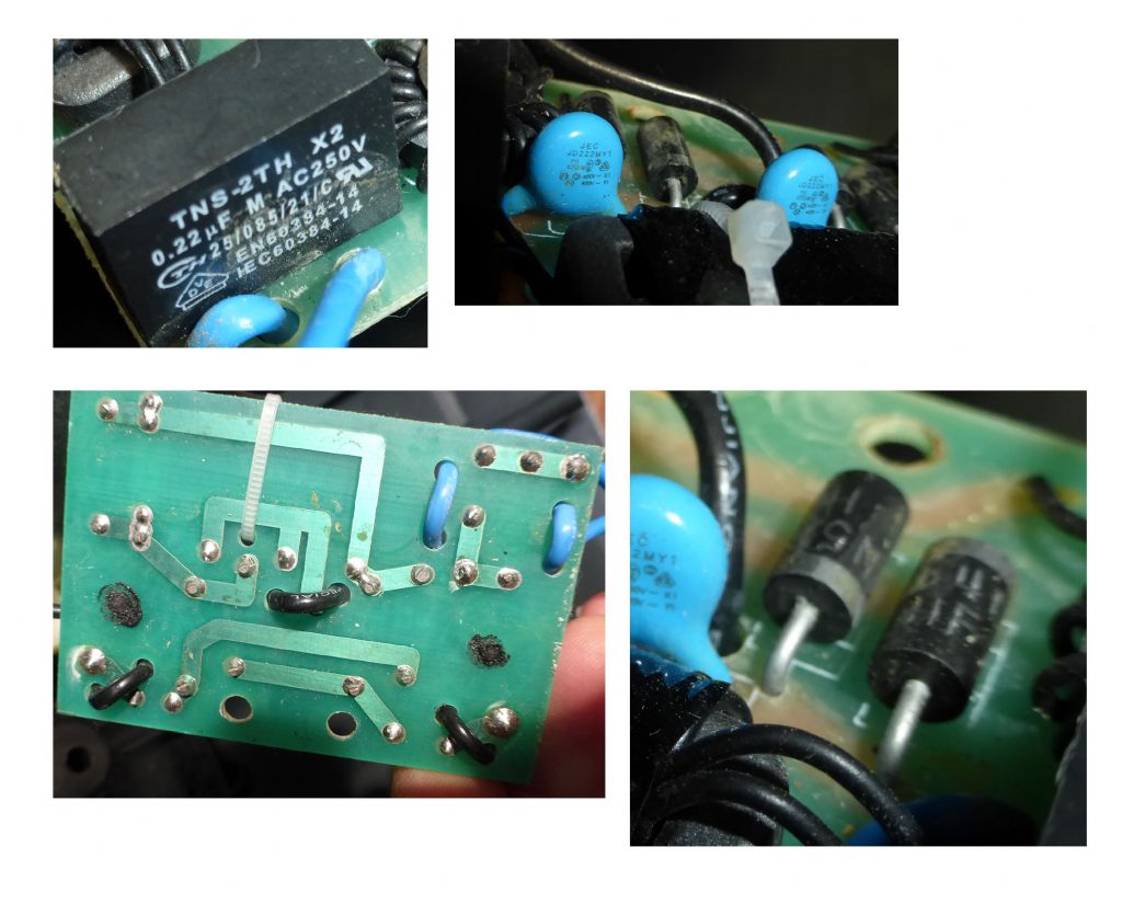
Ok Mark. Just to be clear – all THREE blue jobs are marked JD222MY1 400v- X1 400v -Y1 – correct?
ie, they are identical?
If so , they are all three capacitors and will not be part of your problem. They are 2.2nf 400V class X1/Y1.
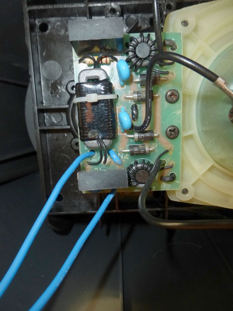
The only two components left are the two toroids – upper and lower right – Measure across each coils wire ends for low resistance.
Then, instead of measuring all wires/cables for continuity, can you apply mains power safely, bypassing the magnetic switch? The wires end in spade terminals – This trick works – BUT BE CAREFUL – THIS IS NOT RECOMMENDED PRACTICE – PLEASE BE CAREFUL…
DISCONNECT THE UNIT FROM THE MAINS SOCKET _ PULL OUT THE PLUG ETC…!!!
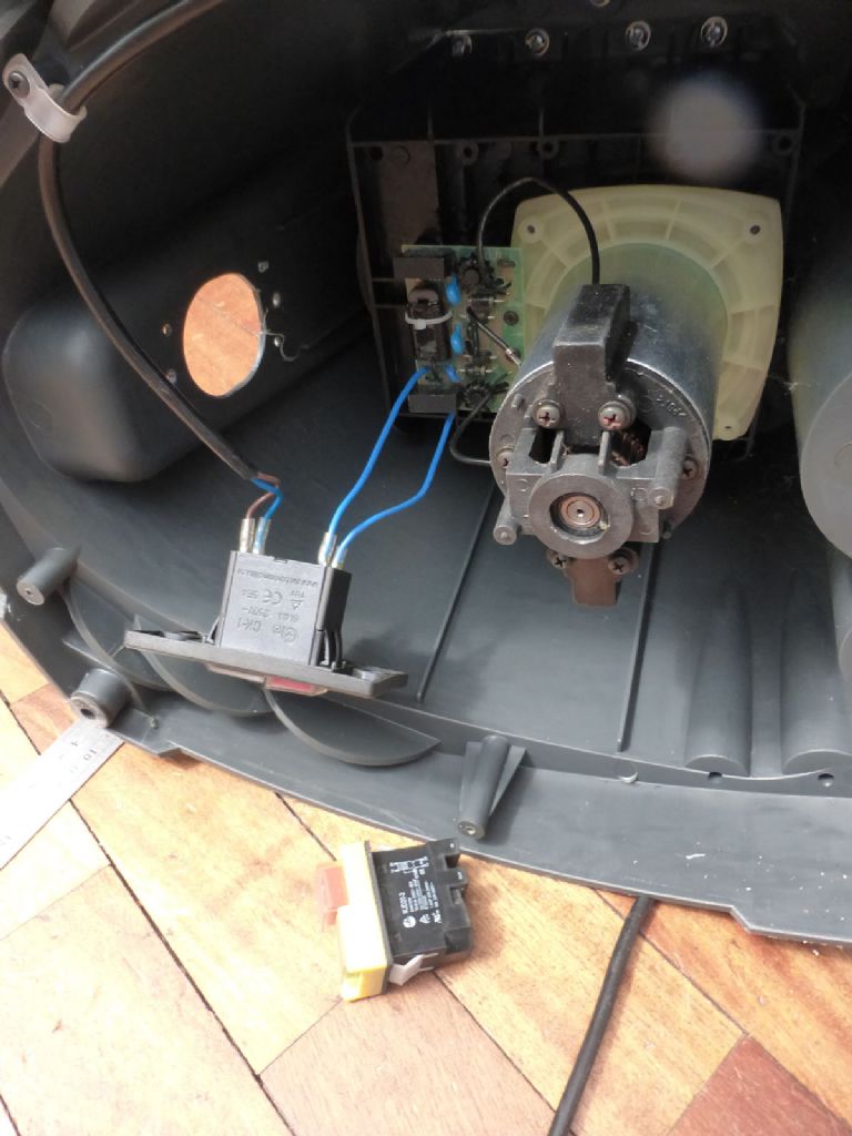
Take two paper clips (!) and press the ends into each of the spade terminals of your cable, ie, in place of the switch. So, using a paper clip as a shorting jumper, connect the PCB end of the cable to the end of the mains cables, in place of the switch. Do this for LIVE and NEUTRAL. Check that the connection is good and firm.
TAPE EACH KLUDGED JOINT UP INDIVIDUALLY WITH GOOD INSULATION TAPE. Make sure there can be NO accidental contact with this thing!
Mains wall plug switch in OFF position, plug in the sander's plug. Make sure the sander motor is stable, the PCB is fixed and nothing can short out because of the kick on startup…
BEING CAREFULL….Switch on..
Did the motor turn or not???
If not..
Switch off and remove wall plug.
You now need to measure some voltages at the motor brushes and on the PCB, so make sure the motor is stable so that you can use one probe per hand and probe about without the pcb moving away etc. You are dealing with a killer voltage here, so CARE IS NEEDED.
Please also make sure your multimeter is safe, eg, probes are in good condition, with no chance of conduction along the probe insulation ( dirty, etc..)
When sure, plug in again, and switch on.
Please be aware that while probing, if there is a loose connection that makes while probing, the motor may start up, startling you. Flayling about with metal probes at that point requires care..
Measure on AC and DC settings, at the motor brush wire connections ( set meter to read 220VAC/220VDC)
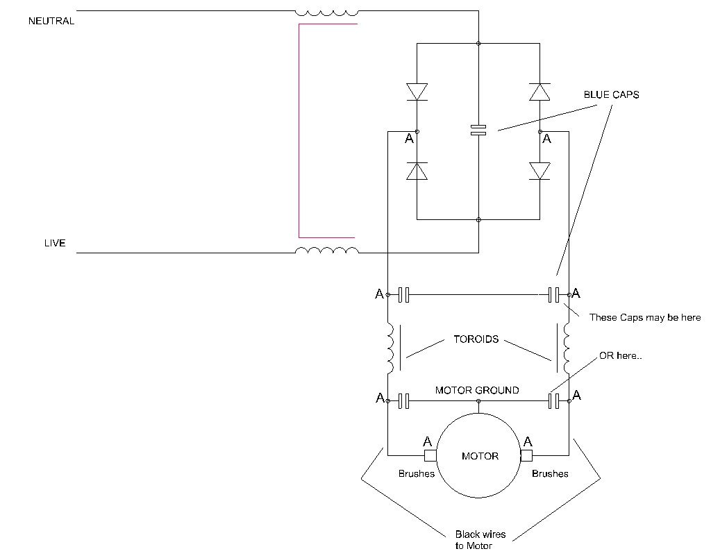
If nothing appreciable, then measure at the leads of the two toroids – the toroids are each in one leg of the rectified mains to the motor it seems – so on the lower right one, on the black wire just below the phillips head screw, and on the uppr right toroid, the black wire just above the phillips head screw.
This should be full wave rectified DC, so meter to DC, but try AC as well ( also 220V settings – or greater depending on meter available settings)
Next…
Joe
Joseph Noci 1.


