New to flaceplatery – a question of balance

Advert

New to flaceplatery – a question of balance

Home Forums Beginners questions New to flaceplatery – a question of balance

Viewing 25 posts - 1 through 25 (of 27 total)
  • Author
    Posts
  • #342828
    Robin Graham
    Participant
      @robingraham42208

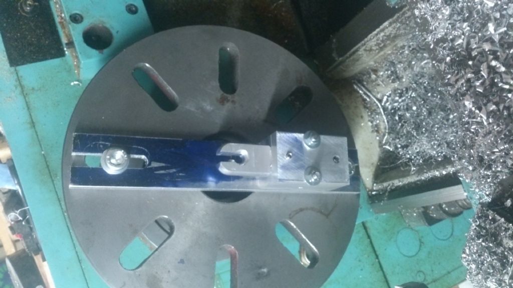
      In another thread (Here's another nice mess…) I asked for advice about workholding. Concensus seemed to be that I should use a faceplate, which is new territory for me. So, (with apologies for the inelegant implementation of the suggestions I received) I knocked this up:

      dsc_0706.jpg


      the aim being to bore out recess at the crotch of the fork from 12 to 20.5 mm diameter. It is actually centered, honest, cameras can lie!

      When I spin it up at 200rpm the lathe is rock solid, but at 330 there's a bit of shaking. A quick calculation (the block holding the workpiece has a mass of about 200 grams with a CoG about 55mm from the lathe axis) tells me that at 330rpm the centripetal force due to the imbalance is about 12N, or around 1kgf, if my calculation is right (questionable nowadays!). Surely there's no way that could affect the (600kg) machine unless there's a resonance?

      So my question is – should I crank up the speed to get over the resonance (if that's what it is) or do I really need to balance the job to avoid injury to limb and lathe?

      Robin


      Edited By Robin Graham on 22/02/2018 22:50:12

      Edited By Robin Graham on 22/02/2018 22:59:56

      Advert
      #9101
      Robin Graham
      Participant
        @robingraham42208
        #342829
        Michael Cox 1
        Participant
          @michaelcox1

          You need the gadget described by Andy Johnstone in MEW 263. The article is entitled "Mounting item on a faceplate".

          I made a similar gadget based on this article last week and it is very helpful for getting a good balance on the faceplate with the moiunted work.

          Mike

          #342839
          fishy-steve
          Participant
            @fishy-steve
            Posted by Michael Cox 1 on 22/02/2018 22:59:38:

            You need the gadget described by Andy Johnstone in MEW 263. The article is entitled "Mounting item on a faceplate".

            I made a similar gadget based on this article last week and it is very helpful for getting a good balance on the faceplate with the moiunted work.

            Mike

            Or you could make Harold Halls version (I wonder if Andy based his design on Harolds???).

            I also find it very useful.

            Steve.


            Edited By fishy-steve on 23/02/2018 00:10:37

            #342840
            Jeff Dayman
            Participant
              @jeffdayman43397

              I'd recommend balancing the job with a similar sized block on the other side of your bar. You could use some plates with holes for the coarse balance and use some washers to fine tune the balance. A faceplate balancing jig as others have mentioned is certainly nice to have but by weighing the loads each side and with careful adjustment you should be fine. Go slow with speed while testing though, and watch your fingers around the edges of the rotating balance blocks.

              Also on your next workpiece – do all drilling and boring before cutting the fork slot. Drilling and boring will be much smoother if you do, and the diameters will be easier to keep on size.

              #342845
              “Bill Hancox”
              Participant
                @billhancox
                Posted by Robin Graham on 22/02/2018 22:48:46:

                So my question is – should I crank up the speed to get over the resonance (if that's what it is) or do I really need to balance the job to avoid injury to limb and lathe?

                Robin

                Brings to mind the old saying: "45 minutes of setting up for 5 minutes of cutting is not unusual."

                I just finished setting up some work on my Myford faceplate. I use the same method for balancing faceplates that I use for balancing my lawnmower blades after sharpening. I hang the bore of the faceplate on a 3 1/2" finishing nail that is locked in my bench vice. The side with the work mounted will naturally swing down to the 6 o'clock position. I hang weights on a bolt/nut fastened to the opposite side of the faceplate using bits of copper wire until the weights are steady at 9 o"clock and the work is steady at 3 o'clock. The weights are then fastened to the faceplate and the balance checked again. Works for me.

                #342847
                Hopper
                Participant
                  @hopper
                  Posted by Robin Graham on 22/02/2018 22:48:46:…

                  …So my question is – should I crank up the speed to get over the resonance (if that's what it is) or do I really need to balance the job to avoid injury to limb and lathe?

                  Robin

                  Dunno about the calculations, math is not my thing, but experience tells me the faster you spin the out of balance faceplate, the more the lathe will attempt to dance across the workshop floor.

                  Traditional fix is to take one of the lathe's change gears and bolt it to the faceplate. In this instance probably on the bolt you have holding the far end of the aluminium flat bar. I'd start with a 25T gear or so and see how that goes. You can get a pretty good idea on a Myford by slackening the belt and moving it away from the spindle and spinning the faceplate. If it always stops at the same spot, that's your heavy spot. Size of the counterweight and how far out from the centre you bolt it affects the balance.

                  If you want to avoid getting swarf all over your change gear, a piece of round bar with a hole drilled through the middle works well, or a selection thereof in different weights. I painted mine red so I can see where it is in flight and avoid banging the toolpost, or my fingers, into it while focusing on the job in the middle of the flight path.

                  With good balance you should be able to machine that job at 600rpm etc. if required.

                  #342848
                  Hopper
                  Participant
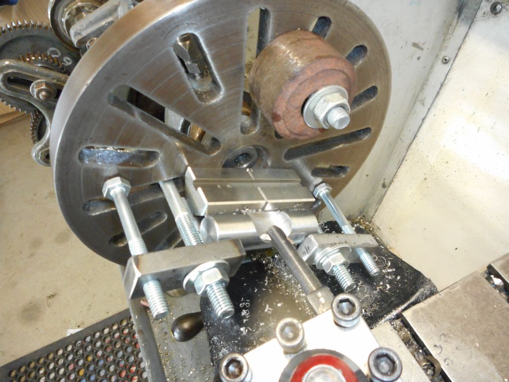
                    @hopper

                    PS, counter weight in action on a tricky faceplate set up, before I learned the hard way to paint the weight a visible colour.

                    dscn1325.jpg

                    #342853
                    JasonB
                    Moderator
                      @jasonb

                      I'd just put some change gears on the light side

                      #342857
                      Anonymous

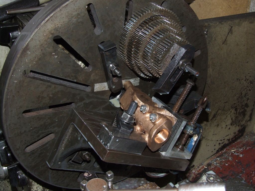
                        Definitely not a resonance problem. When using the faceplate I don't bother with calculations. I just put the headstock gears in neutral, so the spindle is free, and (like JasonB) add gears until the faceplate stays where it is put, at any angle. The change gears are off my dividing head:

                        water pump.jpg

                        The method is good for several hundred rpm. I don't normally run an 18" faceplate much faster than that.

                        Andrew

                        #342875
                        vintagengineer
                        Participant
                          @vintagengineer

                          Even on huge lathes you need to balance the faceplate. The better it is balanced the lest chance there is of turning ovals. We used to cast lumps of lead in baked bean tins and used these as balance weights.

                          #342887
                          Muzzer
                          Participant
                            @muzzer

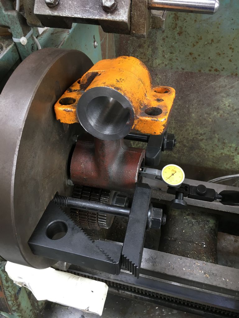
                            Go on then – here's another one.

                            img_5883.jpg

                            Like Andrew, I put the machine out of gear and spin it by hand, then move the counterweight in and out along the slot until it seems close. Bear in mind that the mass of the clamps can also contribute to the solution if they are placed helpfully.

                            When machining a small diameter on a large part, you need a reasonable speed of rotation unless you don't mind taking forever over it.

                            I always take care to ensure the carriage stop prevents unwanted contact between the work and carriage etc(!!) and the nothing else will foul the work anywhere within its range of intended movement. I've taped an extension piece to the carriage stop here (that's the white thing). Once things are spinning, you can't easily tell where things are. There's a lot of kinetic energy in large things spinning fast, so you need to keep clear, including consideration of how / where things might fly off if they came loose.

                            Murray

                            #342891
                            David Standing 1
                            Participant
                              @davidstanding1

                              'Flaceplate'

                              Is that a faceplate for a Chinese lathe?

                              Sorry blush

                              #342913
                              Neil Wyatt
                              Moderator
                                @neilwyatt
                                Posted by Robin Graham on 22/02/2018 22:48:46:

                                So my question is – should I crank up the speed to get over the resonance (if that's what it is) or do I really need to balance the job to avoid injury to limb and lathe?

                                My answer is, what's the rush?

                                You could have done the job at 200 rpm in the time it takes to take a photo, upload it to computer and make the post…

                                You could make a bucketful at 200rpm in the time it takes to make a faceplate balancing fixture!

                                Neil

                                #342919
                                Mike Poole
                                Participant
                                  @mikepoole82104

                                  As Neil says why not just machine it at the fastest speed that it runs happily at. Unless you want to spend a lot of time going for perfect balance then just get it fairly close and see how it runs. As it is out of balance it is unlikely to get better if you increase the speed. Faceplate work is going to most likely be a bit out of balance so it is often going to be run at less than optimum speed. Even a reasonable static balance can run a bit rough if you push the speed too much.

                                  Mike

                                  #343355
                                  Robin Graham
                                  Participant
                                    @robingraham42208
                                    Posted by Neil Wyatt on 23/02/2018 11:41:26:

                                    Posted by Robin Graham on 22/02/2018 22:48:46:

                                    So my question is – should I crank up the speed to get over the resonance (if that's what it is) or do I really need to balance the job to avoid injury to limb and lathe?

                                    My answer is, what's the rush?

                                    You could have done the job at 200 rpm in the time it takes to take a photo, upload it to computer and make the post…

                                    You could make a bucketful at 200rpm in the time it takes to make a faceplate balancing fixture!

                                    Neil

                                    Point taken Neil! I did in fact get the job done at 200rpm. But because this was my first go at using the f(l)aceplate I got interested in how it all works, and how experienced engineers use the thing. This is how I learn – from not just accepting an ad hoc solution to the problem in hand, but trying to generalise from a particular instance.

                                    I think it might well have been a resonance at 330 actually – I took courage and wound it up, it was smoother at higher speed, but more scary – what if something broke loose and the lathe fell over on me! Eee I'm a wimp – when John Stevenson installed the machine I suggested that we should bolt it to the wall in case it wobbled and fell, so he challenged me to tip it over on him. I can still see him standing there unperturbed while I pushed. Wth more than 10 Newtons force.

                                    Thanks to those who suggested bolting changewheels to the light side – hadn't thought of that, stored away for the future, though it wasn't necessary for this job as it happened.

                                    Robin.

                                    Edited By Robin Graham on 26/02/2018 23:11:58

                                    Edited By Robin Graham on 26/02/2018 23:22:59

                                    #343361
                                    not done it yet
                                    Participant
                                      @notdoneityet

                                      Do remember that the bar and bolts on the faceplate may not be balanced, as well as the workpiece being off-centre as well. Also at about 200rpm the resultant force is acting in the opposite direction at a frequency of around 6Hz. You likely don’t notice the up and down motion quite so much as the horizontal effects because up and down are the only times when the weight of the machine or the floor are fully resisting the movement (acceleration) of the machine.

                                      The Tacoma bridge only resonated with a steady cross wind (of 37MPH, wasn’t it?). It weighed a lot more than 600kg but still eventually ‘fell over’ .

                                      #343363
                                      Brian H
                                      Participant
                                        @brianh50089

                                        I don't use newtons so looked up a conversion. 10 newtons works out at 2 1/4 lbs.

                                        Brian

                                        #343364
                                        Sam Longley 1
                                        Participant
                                          @samlongley1

                                          Looking at that picture it looks as if the cutter does not extend to the end of the tool. Or is that just the picture distorting the facts? if not, then how did you cut the full depth of the semicircle without cutting the V block?

                                          Edited By Sam Longley 1 on 27/02/2018 07:59:28

                                          #343365
                                          Hopper
                                          Participant
                                            @hopper
                                            Posted by Sam Longley 1 on 27/02/2018 07:48:11:

                                            Posted by Hopper on 23/02/2018 06:31:40:

                                            PS, counter weight in action on a tricky faceplate set up, before I learned the hard way to paint the weight a visible colour.

                                            dscn1325.jpg

                                            Looking at that picture it looks as if the cutter does not extend to the end of the tool. Or is that just the picture distorting the facts? if not, then how did you cut the full depth of the semicircle without cutting the V block?

                                            Was quite a while ago but from memory the cutter is about level with the end of the boring bar and the V in the V block is the small one, plus the semicircle is less than half the diameter of the bar deep so it did not have to go all the way down.

                                            My son and I did a similar job at the same time when we were making the fabricated body for the Versatile Dividing Head where the semi-circle went lengthways along a piece of 1.5" diameter bar bolted to the faceplate with a bolt up a hole in the bar. On that one, we put a piece of paper between the end of the bar and the faceplate and the plan was to cut right up to the paper, theoretically three thou from the faceplate. But I lost my bottle at the last minute and bored it to within about 10 thou of the end of the bar and cleaned it up with a half round file afterwards. A sacrificial piece of thin plywood or masonite etc would have been more appropriate, or even a piece of aluminium flat plate.

                                            Edited By Hopper on 27/02/2018 08:03:02

                                            #343369
                                            Sam Longley 1
                                            Participant
                                              @samlongley1

                                              I was wondering how else to do that & I think that i would have taken a short steel bar. Bored a hole the diameter of the workpiece. Either put a slit in the bar to allow clamping the workpiece, or a couple of grub screws

                                              Then clamp the bar to the face plate with the workpiece sticking out each end to help set the position. Then bore the bar with a drill to remove most material quickly( make sure that there is enough meat on the bar to one side to get a full hole) then finish off with a boring bar. The diameter would be easier to measure with a full diameter hole & also no interrupted cut. All much closer to the face plate.

                                              But just a thought. I was just trying to work out an alternative to what looks a task that must come up from time to time. Just wondered how others might do it.


                                              Edited By Sam Longley 1 on 27/02/2018 08:14:05

                                              #343370
                                              JasonB
                                              Moderator
                                                @jasonb

                                                You can also do it on the mill with a boring head, easy to set up and no odd weights spinning round. Also if you don't butt the two vee blocks up together but leave a gap you can machine straight through without a worry of crashing the tool.

                                                Edited By JasonB on 27/02/2018 08:20:03

                                                #343384
                                                Hopper
                                                Participant
                                                  @hopper

                                                  Just for a bit of context, I have no milling machine and where I live, getting blocks of steel big enough to bore a hole to fit that bar into is impossible without prohibitively expensive shipping in, and a week or more wait, so it was definitely a "make do" scenario.

                                                  How I set the boring bar to cut the right radius in the job was to hold a disc on a bolt in the tailstock. The disc was the diameter of the scallop I wanted to cut out of the job. The job was marked up at the depth where the scallop was to go to, and was clamped to the f(l)aceprate so that point aligned with the edge of the disc held in the tailstock. Fortunately the diameter of the scallop was large enough that the job rotated around it with a space in the middle so did not foul. (Check this before pressing the start button!) The boring bar started off with light cuts and just kept going until the cut came out to the marked up line that had been aligned with the tailstock disc previously.

                                                  All a bit Heath Robinson but it got us out of a tight spot, having no mill or even boring head to use in the lathe. And it was suitably bizarre to provide an afternoon's entertainment.

                                                  I've since found that such flaceplatery works better for many jobs than trying to mount oversized objects on the spindly Myfrod double swivel vetical slide and trying to mill them. Especially with long or large jobs where the Drummond's limited four inches of cross slide travel restricts milling to that length, or actually less with a flycutter, whereas you can machine an 8 inch flat surface on the faceplate. And compared with the vertical slide, the faceplate is rock solid and some stupid large and oddball jobs can be done on it.

                                                  Next faceplate project planned is a couple of 4" x 4" angle plates. Turn up two cylinders with one end square to the OD, bolt them to the faceplate then clamp/bolt the angle plate (cut from thick 6" angle iron) to the two cylinders and face the surface. So many projects, so little shed time…


                                                  Edited By Hopper on 27/02/2018 10:27:23

                                                  Edited By Hopper on 27/02/2018 10:40:19

                                                  #343418
                                                  Ian P
                                                  Participant
                                                    @ianp

                                                    I use the following method if I need to create a scalloped surface to a precise radius.

                                                    The difficulty of checking the radius dimension applies whether this task is being carried out with the part rotating (as on the lathe like Hopper did) or on the milling machine with a rotating single point cutter. In both cases measuring or setting the radius is quite difficult. Using a trial and error method is OK if you have a mating disk or gauge that you can keep trying in stages.

                                                    To simplify the whole task I change to measuring the diameter that the cutter sweep by attaching a sacrificial bit of metal opposite the scalloped surface so when boring this bit of metal is cut at the same time as the job in hand. It is then easy to measure the diameter of the 'intermittent' hole that is bored.

                                                    I have many mounting blocks (like saddles) to suit diameters from about 50mm to 250mm mostly on the lathe faceplate.

                                                    Ian P

                                                    #343473
                                                    larry Phelan
                                                    Participant
                                                      @larryphelan54019

                                                      Sparey covered this subject very well in his book,well worth a read !

                                                    Viewing 25 posts - 1 through 25 (of 27 total)
                                                    • Please log in to reply to this topic. Registering is free and easy using the links on the menu at the top of this page.

                                                    Advert

                                                    Latest Replies

                                                    Home Forums Beginners questions Topics

                                                    Viewing 25 topics - 1 through 25 (of 25 total)
                                                    Viewing 25 topics - 1 through 25 (of 25 total)

                                                    View full reply list.

                                                    Advert

                                                    Newsletter Sign-up