Need help making a camshaft

Advert

Need help making a camshaft

Home Forums Beginners questions Need help making a camshaft

Viewing 8 posts - 1 through 8 (of 8 total)
  • Author
    Posts
  • #403770
    David K
    Participant
      @davidk77137

      Its for a four cylinder Gypsy engine, the plans show that the cam is built up from separate parts ie. the lobes and bearings are machined then Loctite onto the shaft.

      Now I understand what a camshaft does and how it operates but I have little knowledge of making one. After some research I feel making the lobes on my mill using small flat cuts with the aid of a rotary table would be the best option for me.

      So I need to come up with some figures for the machining process.

      The plans show just one lobe as below

      img_1296.jpg

      There is also a timing guide and some plans for a jig which I am not sure how its used but I assume it may be for a grinding machineimg_1297.jpg

      Advert
      #9613
      David K
      Participant
        @davidk77137
        #403771
        David K
        Participant
          @davidk77137

          Looking at the timing it shows the crank moves 240 degrees for the inlet and 260 for exhaust so that would be

          120 and 130 for the camshaft . On the dials for the jig it states 130 / 140 which confuses me .

          Here is the whole plan , you will need to zoom in img_1302.jpg

          #403776
          Colin Harwood
          Participant
            @balljoint

            Hi David

            there is a web page with a program called camcalc at

            http://modelenginenews.org/design/CamTable.html.

            I have never used it but a member of my club has recently produced a camshat using it

            Hope this helps

            Colin

            #403781
            JasonB
            Moderator
              @jasonb

              As it is a flat flank cam you don't really need camcalc.

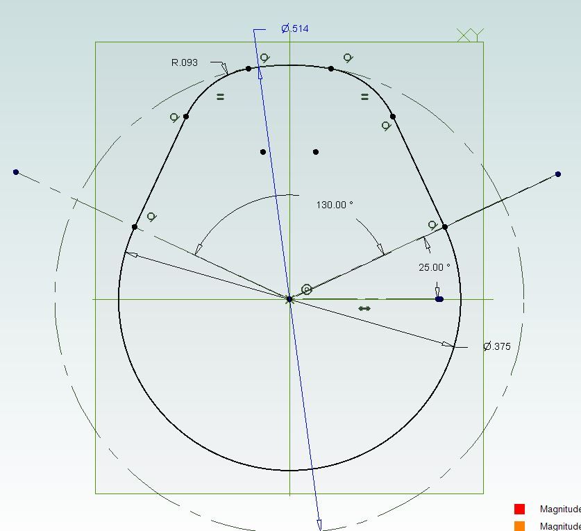
              Just turn up blank with a 0.514 diameter but best not to part off so that you have something to hold.

              Mount on the rotary table and zero it's handwheel, bring the cutter into contact with the 0.514" diameter and zero the axis. Put on a cut of 0.069" ( 0.257 – 0.375/2) lock the slide and make a cut. Rotate say 4 degrees and make another cut, rotarte another 4 degrees and cut.

              carry on like this with the last cut being 230deg ( 360-130*) for the exhaust and the last cut being 240deg (360-120*) for the inlet.

              You will get a flatter topped cam than shown on the drawing and the last job is to file the 0.093" radius and blend in the facets around the base radius

              130cam.jpg

              *The jig probably has a larger angle so that when the tappet clearance is taken into account the cam will have an actual effective rotation therefore opening of 130/120 so machine yours to the larger angle


              Edited By JasonB on 05/04/2019 19:31:41

              #403784
              JasonB
              Moderator
                @jasonb

                As there is not much to come off you could also do it with the blank sticking vertically up out of the rotary table

                Again touch off on the 0.514" dia with the side of the cutter, right hand side of blank would be best, then move the work away from you and put on the 0.069 cut which would be a negative x axis move then wind the work back towards you and stopping when Y = zero. Now turn the table the required 230* or 240* degrees and lock it when you get to that position before feeding the work towards you again to cut the second flank.

                If the 0.069" is too much you can do it in two or 3 passes


                Edited By JasonB on 05/04/2019 19:32:14

                #403791
                David K
                Participant
                  @davidk77137

                  That's great Jason thanks , I presumed the flank had a slight radius, just curious but how do know

                  the flanks are flat.

                  #403792
                  JasonB
                  Moderator
                    @jasonb

                    As it does not give a radius on the drawing presume it is flat.

                  Viewing 8 posts - 1 through 8 (of 8 total)
                  • Please log in to reply to this topic. Registering is free and easy using the links on the menu at the top of this page.

                  Advert

                  Latest Replies

                  Home Forums Beginners questions Topics

                  Viewing 25 topics - 1 through 25 (of 25 total)
                  Viewing 25 topics - 1 through 25 (of 25 total)

                  View full reply list.

                  Advert

                  Newsletter Sign-up