My old Myford ML10 is quite long in the tooth, holding tolerances that are just the other side of 'intolerant'. But having nothing better at the moment and being loathe to part with the amount of money for a worthwhile replacement I continue to use the lathe for what it will do… adding to the tooling along the way.
I have the extended set of gears for metric threads, but on this old girl when cutting metric threads one must engage the half nuts on the leadscrew, not releasing them until the threading operation is finished. Therefore, on fussy little parts (or when turning up to a shoulder), it is better to use a hand crank for precise control.
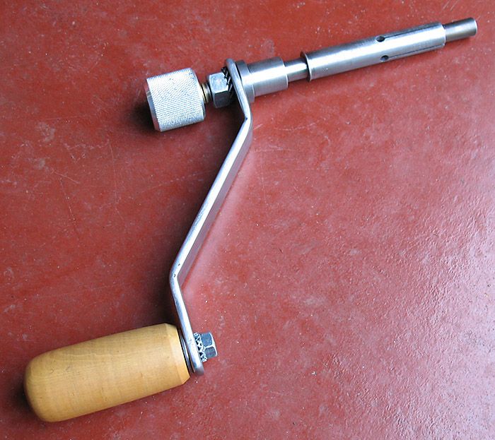
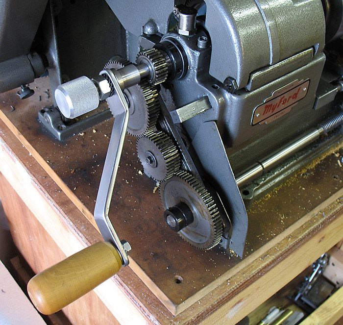
Having no spindle crank, I finally decided to get around to making one. The design I'm using is to be found online at 'Instructables Workshop', created by qthurtle. The photos and design plans of same are to be found at this link: ML10 Lathe Spindle Handle
Well, the project was coming along swimmingly, although the threading of the end for the 12mm nut was a bit of a fuss. I mean, I didn't have the lathe spindle handle that would have made my life easier here, so I ended up grabbing and turning the chuck back and forth by hand (like a rat on a treadmill) for every pass (ouch!). 

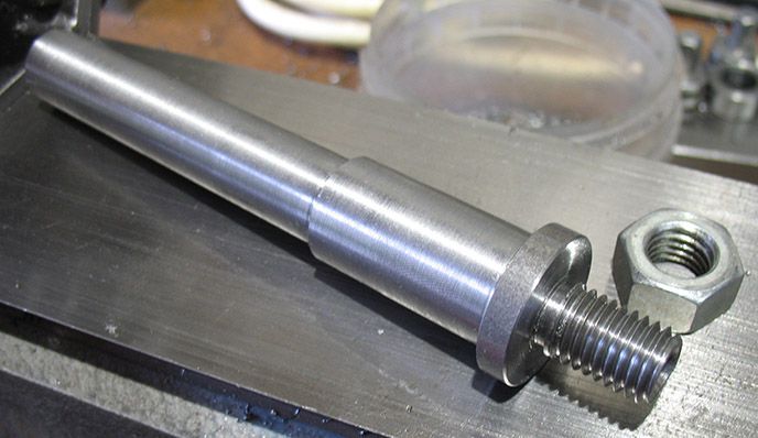
Here is the finished shaft of the spindle crank, just ready for slitting…
…and I was just about to do that when I had a sudden inspiration to try slipping the finished shaft into the rear end of the main spindle for a test fit. And that's when it hit me...
… It wouldn't work!!
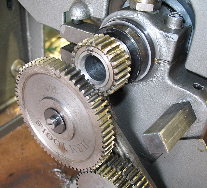
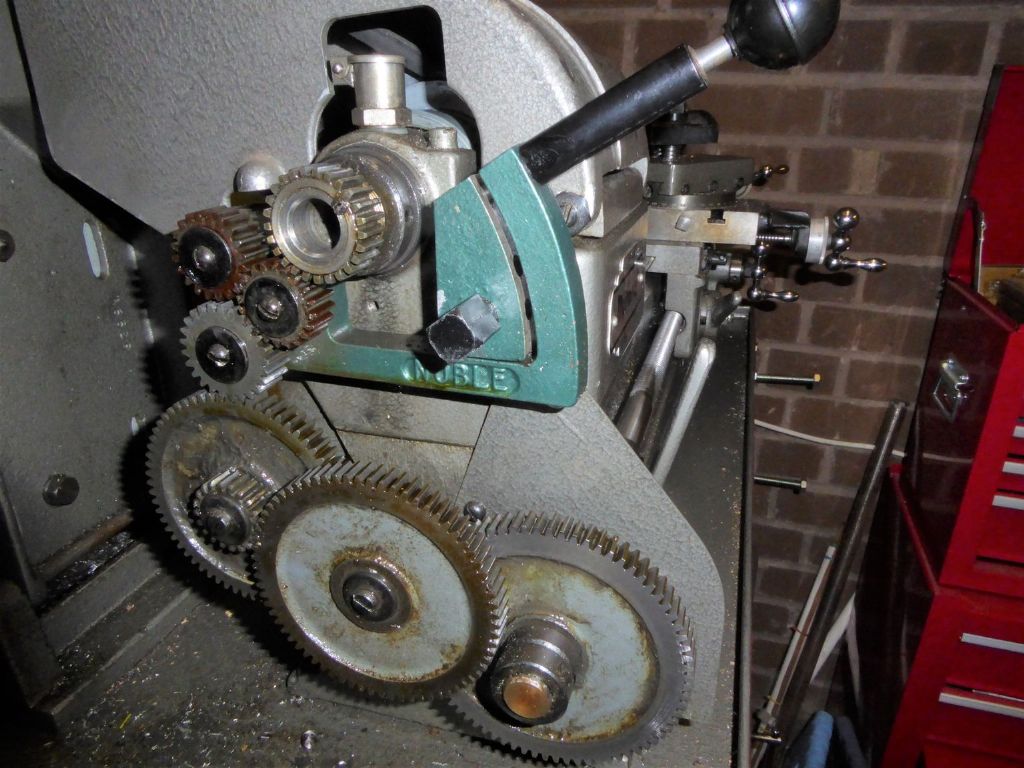
The reason should be obvious from the photo below.

The ML10 does not enjoy a built-in tumble reverse arrangement like the larger lathes made by Myford. As such, the gears on the banjo engage the spindle gear directly and – as should be obvious – in those configurations where the outboard driver gear on the first group is larger than the driven gear of that same group, the teeth of that driver gear can intrude into the space of the spindle through hole. This is almost never the case with the gear arrangements for cutting imperial threads, but for metric… OH BOY!
What you see in the photo above is the first stage gear arrangement for cutting the 1.75 mm stepping for a 12mm thread. The 25-tooth gear on the main spindle drives a 50-tooth gear which is paired with a 63-tooth gear to drive the next group. That 63-tooth gear intrudes almost 2mm into the spindle shaft opening… exactly where the shaft of that spindle crank would be.
Fully 21 out of the possible 27 metric threading gear arrangements for the ML10 use exactly that same 50/63 gear group on the first stage. Like, OUCH!!!
What this means is that the spindle crank as designed won't work for cutting metric threads. Why nobody has ever seen or mentioned this before is beyond me.
However, I have already hit on a solution.

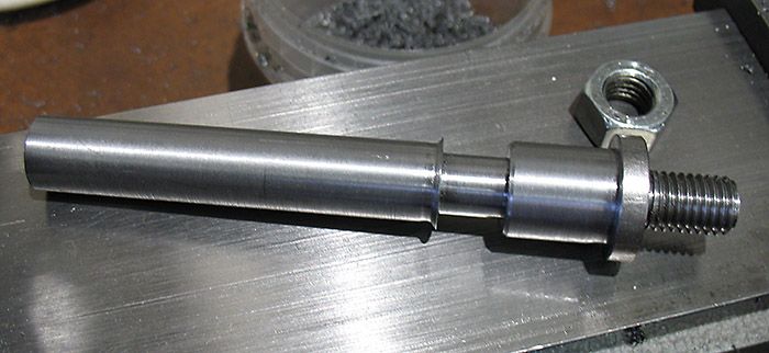
In this photo you can see the alteration to the basic spindle shaft design. I turned a very small 45° shoulder to serve to locate and stop the shaft of the crank in the rear of the main lathe spindle. Behind that the shaft is turned down to a diameter of 12mm to allow it to clear the teeth of that 63-tooth driver gear.

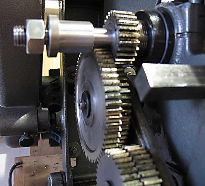
And here a snapshot of the altered crank design in position. It clears that 63-tooth gear quite nicely.
The only other problem is that when using metric threading arrangements with this crank design one must (A) first insert the spindle crank and lock it in place and only then (B) engage the gear train on the banjo and lock it into position. Because of this it will be impossible to have the protective gear cover in place. I don't see this as a major safety issue since the lathe will never be plugged in and under motor power when using the spindle crank.
I'll report further on this when the project is finished. If anyone is interested I can post a measured drawing of the altered spindle.
Douglas Johnston.


