Myford Mandrel thread.

Advert

Myford Mandrel thread.

Home Forums Manual machine tools Myford Mandrel thread.

Viewing 25 posts - 26 through 50 (of 56 total)
  • Author
    Posts
  • #310080
    SteveI
    Participant
      @stevei

      Nige,

      You have not understood my proposed method. You have not:

      1. placed the flat bar (in your case your parallel) half to each side.

      2. used shim to bring it into alignment.

      the whole point of my method is that it can cope with a spindle face that is not co-planar with the axis of rotation. In fact the hole nose can be in a complete mess. It doesn't matter. However as you realised you have not achieved anything with your incorrect interpretation of my instructions. Perhaps my instructions are not well written for that I apologise.

      Furthermore the method I propose does not require your parallel to have its faces parallel to each other. The only requirements is that it have 1 flat surface facing outwards towards your clock and a hole in the middle and you place shim between the spindle nose and the flat bar until the bar clocks true each side as you rotate the spindle 180 degrees back and forth.

      Based on the pictures of your spindle nose I would not trust any reading directly off it sufficiently to green light the removal of metal. This is why I proposed this method.

      When it comes to machine rebuild (I.e. realigning your spindle to the bed and then cleaning up the inner taper and accurately sleeving the outside) you need to be 100% sure about every tool you used to make sure you can trust it. Assume nothing. Now in practice that is not easy to do as a hobbyist with old second hand tools. The only way is to get some help from someone else that has tools that are known to be good enough for the job or buy or make those tools.

      At this stage I respectfully suggest to put it back together as best you can and use it and enjoy it, after all it is a hobby. In the future if you have the means align it more accurately and improve the lathe.

      Steve

      Advert
      #310087
      duncan webster 1
      Participant
        @duncanwebster1

        Whilst I understand the principle of Stevl's method, if the flat bar is say 6" long and the nose is 1" diameter, to change the end to end variation of the bar by 0.001" by shimming against the nose requires shims in 0.00017" increments, which seems a little unrealistic, or am I missing something?

        A similar approach, which doesn't need any shims, is to bolt the test bar as Stevl suggests, then traverse the DTI across the bar, measure the end to end slope of the bar, rotate 180 degrees, measure again. If the spindle is square to the cross slide, the measurements will be exactly reversed. If not you either need to think carefully which way to move the headstock and by how much and try again, or just arbitrarily move it one way and see if it gets better or worse. I think if you adjust it to make the worst of the 2 end to end slopes less it should be the right way, but perhaps others could have a think about it. Only do it a very little bit at a time or you'll get proper confused! This could all take an hour or 2, but should be successful.

        An easier way would be for some kind reader of this thread to lend you a faceplate which will fit, but I can't help.

        Edited By duncan webster on 02/08/2017 23:32:04

        Edited By duncan webster on 02/08/2017 23:32:41

        #310131
        Howard Lewis
        Participant
          @howardlewis46836

          If you now have the 2MT Alignment bar, and the mandrel bore is now cleaned up, why not use that?

          The only inaccuracy might, but should not be, in the relationship of the 2MT taper to the parallel part of the bar.

          Assuming that there is no unacceptable inaccuracy, fit the bar to the Mandrel and with a DTI in the Toolpost, keep adjusting the Headstock position, until traversing the saddle up and down the bed shows no deviation. Check again with the Headstock fully tightened, and correct any error, until the fully tightened deviation reading is Zero.

          Once the Headstock is aligned, you can then turn up the sleeve to allow Series 7 fitting Chucks, Faceplates, Catchplates etc to be used on your ML4.

          Howard

          #310144
          Hopper
          Participant
            @hopper

            Why not put a piece of 1" bar in the chuck and take a light test cut along the length of it, say about 4 inches? Measuring the diameter at each end will give you a pretty accurate indication of spindle to bed alignment.

            Any method using a clock sweeping across a faceplate or flat bar by traversing the cross slide is not telling you anythng about the spindle to bed alignment. It is only telling you about spindle to cross slide alignment, which in an old worn lathe could be miles out of whack due to wear on the carriage dovetails and the cross slide dovetails, so an accumulative error.

            My ML7 carriage bottom surface had had about 30 thou of wear on one end of the dovetail surface that ran on the front vetical shear  of the bed, so skewing the whole carriage around by that much. So the cross slide was miles and miles away from running square to the lathe's main axis. Hence the popularity of the "wide guide" conversion to run on the back shear and bring things back to square again, as well as following the unworn profile of the rear shear.

            Edited By Hopper on 03/08/2017 12:16:23

            Edited By Hopper on 03/08/2017 12:22:41

            #310346
            Nige
            Participant
              @nige81730

              SteveI: I thought I understood your instructions but then made a wrong assumption around using the parallel booted by one end and swinging it through 180 degrees to give me the 'other half' I would have had if the parallel was longer. Realise now that was a mistake.

              Thank you all for continuing the suggestions, I have to go back and look at it and think about it all again 😳

              Howard : The MT 2 finishing reamer has turned up and as soon as I get a big enough tap wrench of some sort organised I can sort out the spindle taper and mount the test bar and see what I have. Also need to order a piece of 1" bar ready to take a cut and see what I get from that.

              Edited By Nige on 04/08/2017 15:10:45

              #310347
              SillyOldDuffer
              Moderator
                @sillyoldduffer
                Posted by Nige on 04/08/2017 15:07:30:

                The MT 2 finishing reamer has turned up and as soon as I get a big enough tap wrench of some sort organised I can sort out the spindle taper …

                Edited By Nige on 04/08/2017 15:10:45

                I'm following this thread with interest and hope no-one minds me asking ignorant questions.

                Nige has a lathe where I don't think he can rely on anything in the way of alignment: the headstock was moved during transport, the lathe's ways and bearings may be worn, the spindle taper is damaged, and the tail-stock alignment must be suspect too.

                Is it a good idea for Nige to begin by cleaning up his spindle with a reamer? I'm worried that hand reaming in a damaged hole wouldn't necessarily stay parallel with the axis, thus creating a false reference.

                I wouldn't know where to start. Can anyone advise on a procedure that checks the alignment of a lathe from scratch. How did Myford align them in the factory?

                Dave

                #310353
                David Standing 1
                Participant
                  @davidstanding1
                  Posted by SillyOldDuffer on 04/08/2017 15:32:07:

                  Posted by Nige on 04/08/2017 15:07:30:

                  The MT 2 finishing reamer has turned up and as soon as I get a big enough tap wrench of some sort organised I can sort out the spindle taper …

                  Edited By Nige on 04/08/2017 15:10:45

                  Is it a good idea for Nige to begin by cleaning up his spindle with a reamer? I'm worried that hand reaming in a damaged hole wouldn't necessarily stay parallel with the axis, thus creating a false reference.

                  Dave

                  I can't see Nige has any choice. The only way he can properly check headstock/spindle to bed and to tailstock alignment is with a test bar in the spindle, and he can't do that unless he can accurately locate the test bar in the spindle taper.

                  #310355
                  Brian Wood
                  Participant
                    @brianwood45127

                    Hello Dave,

                    ​I said in an earlier reply on this post that hand reaming in an already formed Morse taper was effectively self aligning and I stand by that. To force a new alignment needs a great deal of holding in a jig and reaming under power, it is all much more than can ever be done by hand.

                    What Nige has to clean out is some bruising in the mouth of the taper, it won't take long and once cleaned out the reamer will 'bed' into the rest of the taper. That is when he should stop.

                    ​I've seen what Myford used to set up the initial headstock/bed alignment—it was a long test bar, maybe 18 inches long with a Morse taper end and with that you can set the headstock quite quickly.

                    Regards
                    Brian

                    Edited By Brian Wood on 04/08/2017 16:32:42

                    #310563
                    Nige
                    Participant
                      @nige81730

                      Today I made the tap wrench for the MT2 reamer

                      tap wrench 3.jpeg

                      Then I put a lot of oil on the reamer, introduced it to the orifice, pushed gently and twisted. I felt something 'give' so repeated the operation. Something 'gave' a little then it all went very smooth so I pulled out the reamer and on inspection found a couple of tiny bits of metal. I put the reamer back and pushed gently but firmly but it all felt smooth, there was no 'cutting' going on. At that point I felt I probably had the taper as clean as I was going to get it. I thoroughly cleaned out the taper. I then put blue on the taper of the test bar, pushed gently into the spindle and twisted it. On removal I could see that all I had was a smooth smearing of the blue; no signs of high spots rubbing it off and vague darker rings where the taper finished at the bottom and at the mouth of the taper.

                      blue.jpeg

                      #310567
                      Howard Lewis
                      Participant
                        @howardlewis46836

                        Good, Nige!

                        Now you are ready to fit the Alignment Bar and to start clocking it, to adjust the Headstock until you get no change in DTI reading as you traverse the Saddle to and fro along the Bed.

                        Once you reach that happy state, you can then start work in turning up a sleeve to modify the mandrel so that it takes Series 7 Faceplate, Chucks etc.

                        Then you will really be jn business.

                        Howard

                        #310571
                        Nige
                        Participant
                          @nige81730

                          I took the test bar out and cleaned off all the blue and put it back. I mounted a Dial gauge on the cross slide and used a method suggested by Russell.

                          With the dial gauge at centre height I had put it up to the test bar about 2 cm from the nose of the mandrel and definitely clear of the end of the taper. I rotated the bar and took a note of the highest and lowest readings and averaged them. I then moved the dial gauge to the far end of the test bar, about 10 cm away, and repeated the readings, averaging them as well. The difference in the averages gave me the error in alignment of the spindle.

                          I had slackened the head stock clamping nut and studs so I could move the head stock by placing a G-Clamp and moving it relative to the bed.

                          The first test told me the alignment was out by .0232" so I wound the head stock across a bit repeating the readings. After about 10 tests and subsequent adjustments of the head stock I was able to get the misalignment down to .0019" at which point I had run out of adjusting space on the clamp and reckoned I was about there.

                          Having tightened the head stock clamping arrangements down tight I checked that nothing had moved. As a final measurement I put the dial gauge back against the test bar and slowly ran it along it's the length. I was surprised, and pleased when deflection of the gauge along that length was between .01 and .02 mm i.e. .00039" and .00078" Admittedly I did not rotate the bar and try it again.


                          Edited By Nige on 05/08/2017 19:26:31

                          #310573
                          Howard Lewis
                          Participant
                            @howardlewis46836

                            Hi Nige

                            Looks like you are as close to being there as you are likely to be without some stripping and filing of slots.

                            NOW you can modify your machine to take the later accessories, and then the world becomes your oyster.

                            Well Done!

                            Howard

                            #310576
                            Nige
                            Participant
                              @nige81730

                              Thank you Howard. I just need to get in some steel stock and practice turning etc. Also sort out tool height adjustment method but that shouldn't be too much of a problem.

                              #310651
                              SillyOldDuffer
                              Moderator
                                @sillyoldduffer

                                Thanks Dave and Brian; I am reassured about reamers!

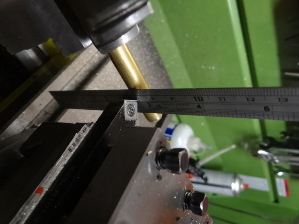
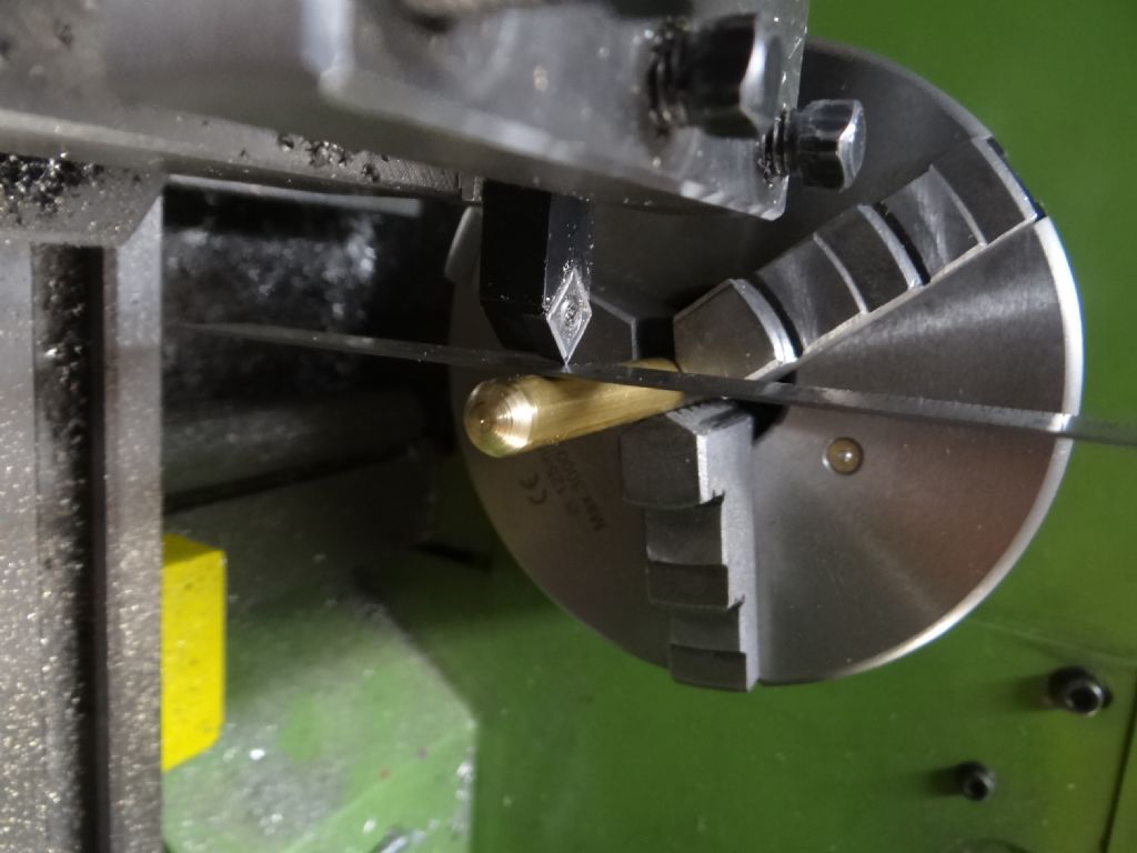
                                Nige, the easiest way to set tool height is to nip a steel rule at its centre point vertically between the work and the tool point If the tool is too high, the top of the rule will lean over the work. If the tool is too low, the bottom of the rule will lean under the work. The tool is at the right height when the rule is truly vertical.

                                dsc04505.jpg

                                Although exaggerated by camera tilt, this tool is slightly high.

                                dsc04506.jpg

                                Dave

                                #310653
                                Russell Eberhardt
                                Participant
                                  @russelleberhardt48058

                                  Nice one Dave.

                                  If you use something thinner like a razor blade you will get more sensitivity. I use the same method for aligning the tailstock, pinching the blade between the headstock centre and the tailstock centre.

                                  Russell

                                  #310658
                                  SillyOldDuffer
                                  Moderator
                                    @sillyoldduffer
                                    Posted by Russell Eberhardt on 06/08/2017 11:38:27:

                                    Nice one Dave.

                                    If you use something thinner like a razor blade you will get more sensitivity. I use the same method for aligning the tailstock, pinching the blade between the headstock centre and the tailstock centre.

                                    Russell

                                    Good point about sensitivity Russell: I should have mentioned that the steel rule in the photos is thinner than most. (One advantage of it being cheap!)

                                    I hadn't thought of using the same method for tailstock alignment using a pair of centres. Good idea!

                                    Thanks,

                                    Dave

                                    #310671
                                    NJH
                                    Participant
                                      @njh

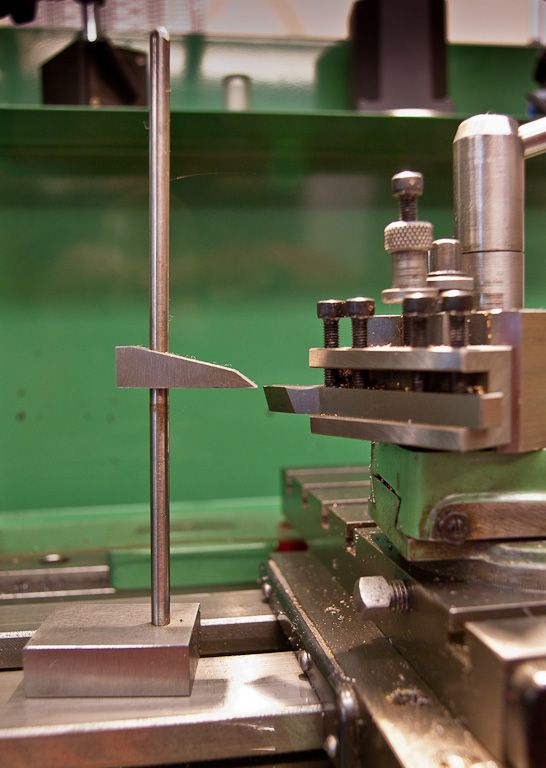
                                      If you have a little time to spare making up one of these and keeping it on the lathe is useful. ( I can never find my 6" rule when I need it! )

                                      Norman

                                      Tool Height

                                      Edited By NJH on 06/08/2017 13:31:23

                                      #310734
                                      Nige
                                      Participant
                                        @nige81730

                                        I was looking at the ML4 thinking about how I would make the sleeve to enable me to mount series 7 back plates etc. My concern is how far the machining area id from the tool post. The ML4 has a permanent gap in the bed and with the saddle as close to the head stock as possible while still being fully supported the cross slide edge is 3 1/4" from the rear of the mandrel at the furthest point that i would need to cut. My worry is that 3 1/4" is long way for a tool to overhang that is having to make an accurate cut.

                                        bed end and gap.jpeg

                                        Questions: Should I be worrying about the distance the tool will have to reach?

                                        Can I bring the saddle closer to the headstock even though it means less support from the bed and if so how much saddle overhang might I get away with?

                                        Anything else I should consider?

                                        #310735
                                        larry Phelan
                                        Participant
                                          @larryphelan54019

                                          Hi NJH,

                                          Like you,I can never find my rule,or anything else,for that matter,so I made up something like your,s,although not quite as neat,but it works ! And it never gets lost.

                                          Something like "Great minds think alike" Dont mind the second part !

                                          #310737
                                          JasonB
                                          Moderator
                                            @jasonb

                                            It's no further than a boring bar may have to reach, best to use one of those mounted upside down (run in reverse) and with the top slide as far towards the headstock as possible.

                                            Edited By JasonB on 06/08/2017 20:21:42

                                            #310864
                                            Nige
                                            Participant
                                              @nige81730

                                              NJH: Thanks, something along those lines is on the list of things to make.

                                              JasonB: Thanks, I do have a couple of what I think are reasonable sized boring bars. Just need to get some steel and have a go

                                              #310865
                                              Nige
                                              Participant
                                                @nige81730

                                                Having got the head stock aligned as best I can for the time being I mounted a piece of EN1A and took a test cut over about 1 1/2" measuring diameter at both ends of the cut after each pass and noting the difference. After 6 or 7 cuts the difference was averaging out at about .001" the narrower dimension was always nearest the chuck.

                                                Not sure what conclusions to draw from this…Good, bad or indifferent ?

                                                test cut.jpeg

                                                #310872
                                                SillyOldDuffer
                                                Moderator
                                                  @sillyoldduffer

                                                  What diameter is that rod Nige? It looks fairly small, less than 1/2". If so it may be bending under the force of the cut. As there's more leverage at the far end of the rod you get a slight taper.

                                                  Dave

                                                  Edited By SillyOldDuffer on 07/08/2017 15:50:14

                                                  #310875
                                                  Nige
                                                  Participant
                                                    @nige81730

                                                    Dave:Thank you, I think it was 1/2" and I will be glad if that s the explanation. I am in the process of ordering something thicker to repeat the test on and I guess I will get more from that

                                                    #310882
                                                    Jon Gibbs
                                                    Participant
                                                      @jongibbs59756
                                                      Posted by Nige on 07/08/2017 15:15:41:

                                                      Having got the head stock aligned as best I can for the time being I mounted a piece of EN1A and took a test cut over about 1 1/2" measuring diameter at both ends of the cut after each pass and noting the difference. After 6 or 7 cuts the difference was averaging out at about .001" the narrower dimension was always nearest the chuck.

                                                      Not sure what conclusions to draw from this…Good, bad or indifferent ?

                                                      It could be that the stock is bending away from the tool but if the cuts are light and the tool sharp enough then it could be fixed by at least one of a couple of things.

                                                      1) The headstock needs to be turned clockwise in relation to the bed – the mandrel end needs to come forwards, or

                                                      2) The bed is twisted and the front tailstock end needs to be lifted upwards to bring on the cut more towards the tailstock end.

                                                      HTH

                                                      Jon

                                                    Viewing 25 posts - 26 through 50 (of 56 total)
                                                    • Please log in to reply to this topic. Registering is free and easy using the links on the menu at the top of this page.

                                                    Advert

                                                    Latest Replies

                                                    Home Forums Manual machine tools Topics

                                                    Viewing 25 topics - 1 through 25 (of 25 total)
                                                    Viewing 25 topics - 1 through 25 (of 25 total)

                                                    View full reply list.

                                                    Advert

                                                    Newsletter Sign-up