Marine Engine Flywheel Fixing

Advert

Marine Engine Flywheel Fixing

Home Forums General Questions Marine Engine Flywheel Fixing

Viewing 25 posts - 1 through 25 (of 27 total)
  • Author
    Posts
  • #27900
    Ramon Wilson
    Participant
      @ramonwilson3
      Advert
      #520747
      Ramon Wilson
      Participant
        @ramonwilson3

        Hi, does anyone know how a flywheel would have been retained in place on a full sized compound marine engine. Keyed yes, but how was it held in position laterally.

        Any help or knowledge would be most appreciated but I'm afraid in this instance a grub or set screw simply won't do wink

        Thanks in advance – Tug

        #520843
        JasonB
        Moderator
          @jasonb

          I seem to recall seeing them drilled for bolts into an integral flange on the end of the crankshaft but could be wrong.

          #520852
          Ramon Wilson
          Participant
            @ramonwilson3

            So the flange is part of the crankshaft then ? That would make sense – drive from a key but held by a bolted flange.

            Thanks Jason but if anyone has any full size knowledge too that would be appreciated.

            #520854
            JasonB
            Moderator
              @jasonb

              A bit later than what you are working on but shows the flange, flywheel a bit further along the bottom row of photos

              #520856
              David Senior
              Participant
                @davidsenior29320

                I've had a quick look through some books on marine steam engines and I can't find any that show a flywheel, but they all appear to have a flange as Jason suggested. I doubt if you would get keyways on the bigger stuff.

                Dave

                #520860
                MichaelR
                Participant
                  @michaelr

                  Flange fixing marine crankshaft Link

                  MichaelR

                  #520869
                  Journeyman
                  Participant
                    @journeyman

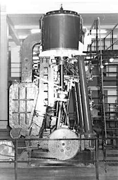
                    This is the crankshaft end of the triple expansion engine from the TS Glen Strathallan. Long time since I was a cadet on board and can't remember what went where but the flange is there. The picture is in the Science Museum where the engine ended up so they have used the flange with a chain wheel to provide a drive for the display. Cant say I'm impressed by the chain tension!

                    glenstrathengine.jpg

                    John

                    Edited By Journeyman on 18/01/2021 19:34:18

                    #520879
                    bernard towers
                    Participant
                      @bernardtowers37738

                      Our leak compound has a keyed flange on the crank with two M8 socket headed grubscrews screwed through the flange directly over the key. Lateral movement is taken care of by the prop shaft thrust bearing mounted on a keel block.

                      #520880
                      Paul Kemp
                      Participant
                        @paulkemp46892

                        I don't think many decent sized marine steam engines had flywheels, instead they relied on the inertia in the shafting and prop and were flange drive. All the large marine diesels I have worked on have had flange mounted flywheels, no keys just fitted bolts and high torque.

                        If a flywheel were fitted to a small marine steam engine I would expect it would be secured with a taper gib head key. That's how traction engine flywheels and line shaft pulleys etc were retained, having had to remove some I can vouch for how tight they can hang on! Either that or mounted on a taper on the end of the crank in the same manner shaft couplings are (both with and without keys) the modern type of taper coupling using oil injection to seat and remove are a thing to behold, they can come off with a significant bang and not something you want to be messing with without some restraint in place.

                        Paul.

                        #520883
                        Ramon Wilson
                        Participant
                          @ramonwilson3

                          Hi guys,

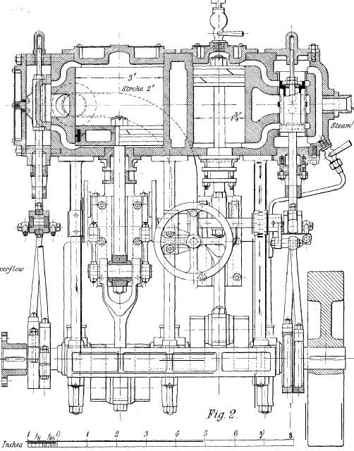
                          Thanks to all for your input on this matter including Trevor's PM. The engine I am building (the 1924 ME published Marine Compound off the John Tom site) is not fully scale but is a design based on full size practices. I'd like to make it as close to full size as possible where I can hence the question.

                          Making the flange part of the crank seems the way to go but from what I can see so far is that the flywheel bolts directly to the flange and not seating on the shaft itself.

                          I guess this is one of those areas where near every manufacturer had a variation on a theme. Interesting.

                          My thanks again – much appreciated

                          Tug

                          #520888
                          Paul Lousick
                          Participant
                            @paullousick59116

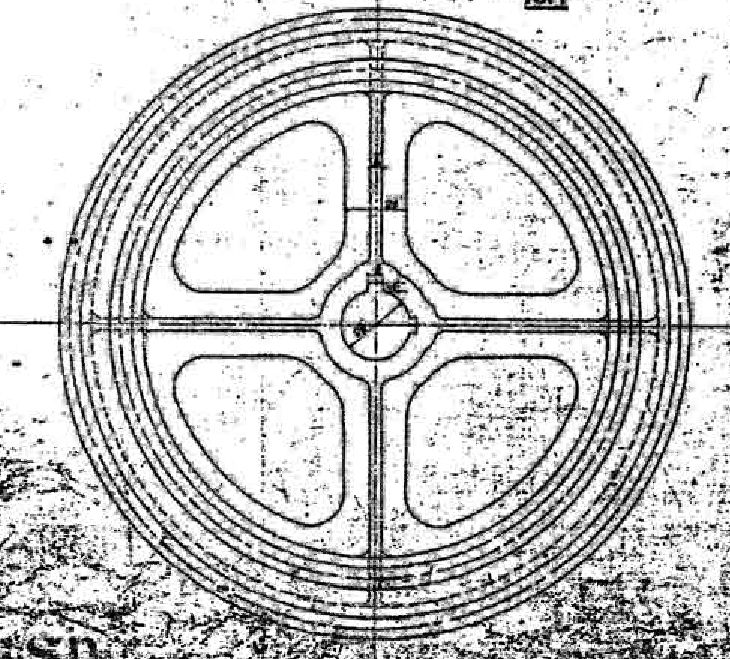
                            Flywheels were also fitted with 2 taper keys, spaced at 90 degrees to each other on on some early steam engines to give a more secure mounting.

                            Paul.

                            flywheel keys.jpg

                            #520894
                            noel shelley
                            Participant
                              @noelshelley55608

                              In the context of marine use flywheels were not the order of the day, eg the 2500 Ihp triple expansion engine used in the british designed Liberty ships had no flywheel just a flange that was bolted to the shafting. But for stationary use a flywheel may well be used, eg The Dover engine, a triple expasion engine used for water pumping at Forrncett st Mary, near Norwich and still steamed. Noel.

                              #520903
                              Ramon Wilson
                              Participant
                                @ramonwilson3

                                Paul, Noel, Thanks for this further input.

                                I have several books I can refer to for stationary engines but nothing that covers marine engines. The design (ME May 1923 not '24 as previously stated) I am working to is described as following "full size practices of a kind of engine fitted to a small coastal steamer". It is shown with a flywheel – which to my mind does look a little large in diameter but that's another matter – it is merely shown keyed to the shaft with no flange or means of retention at the forward end.

                                As for a flywheel at all – as drawn the cranks are at 180 degrees though the author states it can be built with them at 90. Whether that's the reason for the flywheel is not stated but the Elliot and Garrod 'monkey' triple (two cylinders in line the HP in tandem with the intermediate) had cranks at 180 degrees and had a centrally mounted fairly substantial flywheel that also acted as the central crank web.

                                I will continue researching – confirmation if one would have actually been fitted now being the first priority, it's fixing method if so now the second.

                                My thanks again

                                Tug

                                #520915
                                JasonB
                                Moderator
                                  @jasonb

                                  Ramon, a tapered key and mating keyway would be one way to keep it on the shaft. Text does mention two tapped holes into the end of the (slightly shorter? ) crankshaft and a disc to retain the flywheel. Whether that was usual practice I don't know.

                                  Hard to know if the original may have had a flange and it was just omitted to save having to make split eccentrics as you can't slide them onto the shaft if there is a flange in the way

                                  This is the engine in question for those not familiar with the design, full size was about 8ft tall and 5ft long.

                                  1923.jpg

                                  Edited By JasonB on 19/01/2021 07:41:11

                                  #520920
                                  Ramon Wilson
                                  Participant
                                    @ramonwilson3

                                    Hello Jason,

                                    Although I read through initially I have to confess to having missed the fixing method in the text and was focusing more on the drawing!! It would work of course but hardly be in keeping I feel. Having said that I spent a long time last night looking at countless images I could find. Most if not all seem to confirm that marine engines rarely had a flywheel. Having said my small collection of books did not cover marine engines I remembered some catalogue reprints I have.

                                    Several feature closely similar compound engine designs – none of which feature a flywheel.

                                    Virtually all model variants appeared to have a flywheel – obviously to help smooth out the reciprocation at the much smaller scale so it looks like a compromise – because I will run this on air I will fit one as such though slightly smaller in diameter to an integral flange as you suggested and what most engines do seem to feature at both ends. I noticed many of them have barring holes in the rim of the larger flange as well so something else to add.

                                    Thanks again for all the input – just what a forum is for yes

                                    Ramon (Tug)

                                    #520984
                                    Howard Lewis
                                    Participant
                                      @howardlewis46836

                                      It is quite common for flywheels to be located to the flange by either a dowel, for location rather than a keyway, ( to avoid a stress raiser ) or by fitted bolts, with one displaced so that the wheel will only fit in one angular position.

                                      In marine practice, the shaft and propeller inertia would probably act as a flywheel to reduce cyclic irregularity, probably aided by the hydraulic damping of any torsionals.

                                      With the likely length of the shaft, and the inertia of the prop, the natural frequency would tend to be low.

                                      Howard

                                      #521010
                                      noel shelley
                                      Participant
                                        @noelshelley55608

                                        Gentlemen, REMEMBER, this is a direct drive, reversing engine in a moving vessel that must be able to maneouver, a flywheel will be a REAL handicap. On a non reversing engine the flywheel will help to smooth things out, eg a mill engine.

                                        I worked on a diesel powered vessel. It had a direct drive, reversing, air start diesel engine of 500hp, the flywheel was very small, only really fit for baring. Maneouvering in a tight spot you had to pray to the good Lord that you did not run out of air. If you did, luck was often in short supply Too. Noel

                                        #521011
                                        10ba12ba
                                        Participant
                                          @10ba12ba

                                          Watkins, Vol 10, part 1, plate 30 shows at least one gib head key fitted to the inboard end of a flywheel or coupling which incorporates what looks like internal barring gear.

                                          Ramon, you have a PM

                                          H.

                                          Edited By 10ba12ba on 19/01/2021 14:10:02

                                          Edited By 10ba12ba on 19/01/2021 14:22:18

                                          #521013
                                          DiogenesII
                                          Participant
                                            @diogenesii

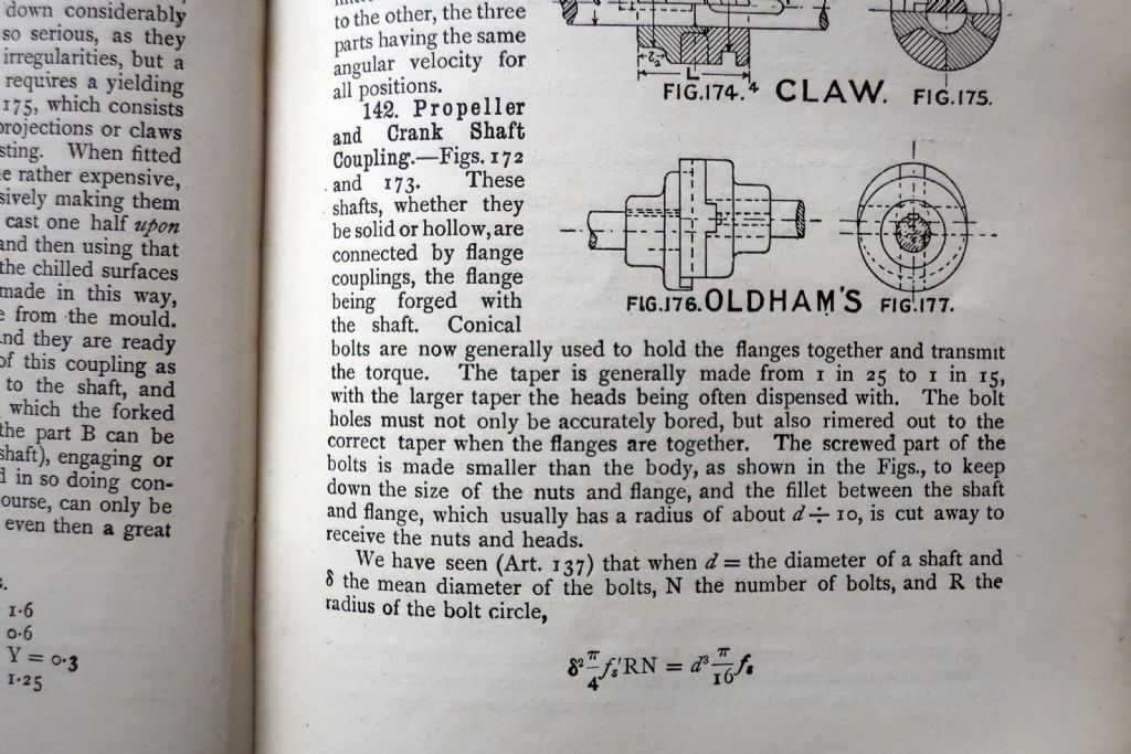
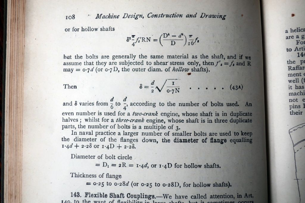
                                            ..and just to complicate matters further, here is another description containing the bolting arrangements to be employed..

                                            img_1606.jpg

                                            img_1608.jpg

                                            ..from Henry Spooner's 'Machine Design Construction and Drawing' (Longman's, Green & Co., 1908) included because of it's direct relevance to the specific context of the discussion.

                                            ..By the terms 'Two Crank' & 'Three Crank' I surmise he means two- and three-throws – i.e. twins or triples..

                                            Edited By DiogenesII on 19/01/2021 14:36:43

                                            #521016
                                            JasonB
                                            Moderator
                                              @jasonb

                                              In the end it may well come down to what is going to allow the model to tick over smoothly on air as you will not have a prop and shaft and presumably a thrust box to smooth things out. There is also the lack of expansion from running the compound on air to further complicate things.

                                              Prestons has a few engines over six pages of similar size that may be worth a look through , this Thornycroft on the last page is probably the clearest flange mounted flywheel and also about the largest diameter though it is quite narrow. There are quite a few more engines with more compact ones complete with barring holes.

                                              If all else fails Ramon you could keep the flywheel in place with your favourite JBWelddevil

                                              #521031
                                              SillyOldDuffer
                                              Moderator
                                                @sillyoldduffer

                                                Had a look at my American Marine Engineering Book circa 1945.

                                                Volume 1 describes the US Maritime Commission Engine of 1940 in considerable detail. Quite interesting – it's the Triple Expansion Steam engine used to power Liberty Ships. Rationale almost engineering firm could make them, and reliable simplicity, not high-performance or fuel economy. Goes on to describe Woolf Engines, Lentz Engines, Steam Turbines and Maritime Diesels. None of these engines have flywheels.

                                                However, Volume 2 has a section on vibration, and mentions flywheels as a way of controlling it. My idea of a flywheel is a hefty beast designed to store a lot of energy to deal with varying loads. Not how this book sees them. Small, if used at all, and intended to deal with resonances.

                                                Looking at the engine plans in Volume 1, although they don't have separate flywheels, they do have heavily weighted cranks. Although the main purpose of the weights is balance, they would also have a flywheel effect, maybe sufficient to not need a separate flywheel at all. There are also features like the engine / propeller-shaft couplings that must act as small flywheels. The reduction gearbox on a steam turbine looks like a hefty flywheel – might take a turbine ship a few miles to stop!

                                                Mill engines and pumps see varying loads and for them a big flywheel must be very helpful. Maritime engines don't have the same need for a flywheel because they deliver power into a steady load for weeks on end. I suppose a ship engine's worst nightmare is when the propeller dips in and out of the sea during a storm.

                                                Dave

                                                #521131
                                                Ramon Wilson
                                                Participant
                                                  @ramonwilson3

                                                  Guys – my thanks again for your continued interest in my question.

                                                  I have no real knowledge as such of full size marine engines to call upon and just assumed from the wheel fitted to this design clearly described as a Marine Condensing Compound that they would have one fitted.

                                                  I can see now that this is not, or very rarely the case. I mentioned the 'Monkey' triple produced by Elliot and Garrood as having quite a substantial one but this was part of the design as said and acted as part of the crankshaft make up. During the research carried out with my sorely missed friend on this engine one thing that came to light was – with the 180 degree cranks how difficult it was for the driver to go from forward to reverse when having to manoeuvre the vessel. That bears out Noels input for sure.

                                                  I have the Spooner book but did not consider it because this is more on land based machine design though having checked it out there is a description of a marine coupling further on using fitted tapered bolts.

                                                  So mulling all this over today between machining ops on the base I've concluded this engine will be statically displayed without a flywheel but with flange couplings at each end. When – if – it is run for display then a flywheel can be temporarily fitted to smooth the slow speed out.

                                                  Sounds good? – I hope so

                                                  Regards – Tug

                                                  PS – Jason , I did spot the Thornycroft last night.yes

                                                  And as you would expect by now JB Weld will feature a fair bit on this build but maybe not quite as you suggest wink

                                                  Edited By Ramon Wilson on 19/01/2021 20:28:41

                                                  #521184
                                                  John Olsen
                                                  Participant
                                                    @johnolsen79199

                                                    I see I'm a bit late to this party, but I would confirm that the majority of full size marine engines would not have a flywheel, at least not as such. The length of shaft and the big propeller would usually provide all that is needed.

                                                    I mostly recall shafts being plain with keyways rather than flanged. Thrust bearings can be multiplate or the later Mitchell type. Sometimes the thrust bearing has been incorporated in the engine bed plate, but I think not usually.

                                                    Modern small steam launches do usually include a flywheel. This is I think because the relatively smaller prop and shaft don't provide a lot of inertia. It is also sometimes convenient to be able to pull the engine over a little, although I would not advise this since it can be a bit hazardous. Crankshafts are usually 90 degrees for a twin to give self starting. On mine, each crank has balance weights, effectively attempting to balance each cylinder as it it was a single. You can't really balance a 90 degree parallel twin of course. The self starting feature is more important than balance at the sort of revs we use in steam launches anyway, and a compound should have a simpling valve fitted to allow giving the LP a shot of steam to move the HP off top dead centre. This is not a full simpling arrangement usually.

                                                    Even with a 10 inch diameter by three inch wide flywheel, my Leak compound can reverse faster than the eye can see, so the inertia in the setup is not a great deal of concern. It takes a lot longer to overcome the inertia of over two tonnes of boat! I think the same probably applies with full size turbines, where even though the reversing turbine is usually smaller, the real problem is the inertia of the hull, not the gears.

                                                    John

                                                    #521222
                                                    Ramon Wilson
                                                    Participant
                                                      @ramonwilson3

                                                      Thanks for that further input John – it all adds to the info.

                                                      I'm pretty relaxed now about not fitting one as my last post. From the outset I thought that the diameter as drawn was rather excessive anyway.

                                                      It is my intention to have a thrust bearing installed and possibly a stub shaft with a propeller fitted but that's a long way off as yet.

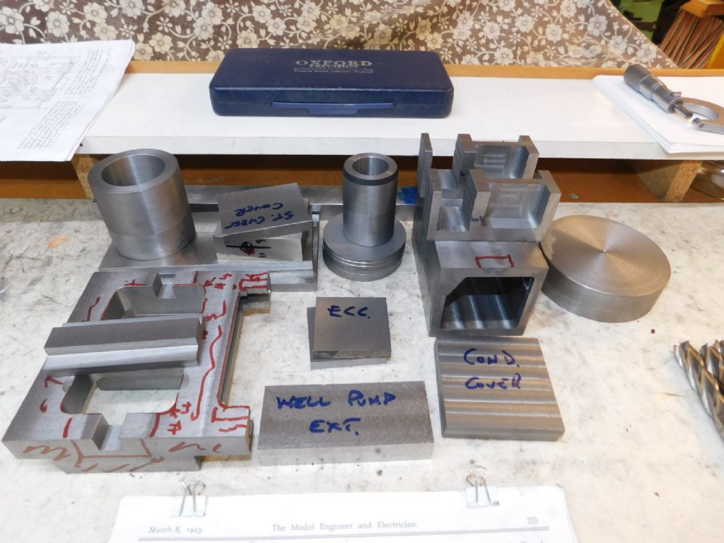
                                                      The engine parts are being machined from cast iron bar stock and like the double ten cylinder done some time ago will be of composite construction using JB Weld to hopefully create the effect of castings. Here's the major parts roughed out ready to go

                                                      marine compound (14).jpg

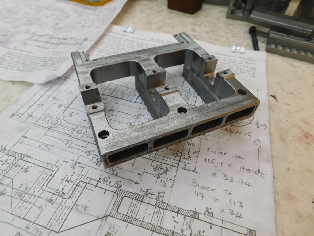
                                                      I made a start this week beginning with the base – from a solid slab of cast this was after yesterday's session

                                                      marine compound (20).jpg

                                                      There's a fair bit of swarf come off of there so far and still some to come!

                                                      Regards – Tug

                                                    Viewing 25 posts - 1 through 25 (of 27 total)
                                                    • Please log in to reply to this topic. Registering is free and easy using the links on the menu at the top of this page.

                                                    Advert

                                                    Latest Replies

                                                    Home Forums General Questions Topics

                                                    Viewing 25 topics - 1 through 25 (of 25 total)
                                                    Viewing 25 topics - 1 through 25 (of 25 total)

                                                    View full reply list.

                                                    Advert

                                                    Newsletter Sign-up