Laser DRO sensor

Advert

Laser DRO sensor

Home Forums The Tea Room Laser DRO sensor

  • This topic has 31 replies, 10 voices, and was last updated 9 July 2020 at 17:40 by Michael Gilligan.
Viewing 25 posts - 1 through 25 (of 32 total)
  • Author
    Posts
  • #484593
    John Hinkley
    Participant
      @johnhinkley26699

      I have been mulling over a suggestion I first mooted in 2013! It concerned the possible use of a mouse sensor as a device for producing an output to a display for use as a DRO for lathes, mills and the like. There have been a number of threads lately regarding the fitment of scales to, particularly, lathe cross slides and how they might restrict the movement of them and also interact with the chuck and/or tailstock. That set me off thinking, again. Always dangerous, but having a brief interlude in the metal-mangling, I thought – why not?

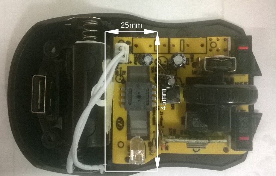
      So I took an old mouse to pieces and had a look at the innards:

      mouse innards.jpg

      Not a laser mouse, but an LED one. I don't have one of the former. The rectangle indicates where I reckon the business end of the positioning electrickery is. Research has lead me to the conclusion that a laser sensor can detect movement changes of as little as 1 to 2 microns, better than my DRO glass scales, at 5µm. I therefore thought that if the sensor could be mounted in a suitable housing and secured to the cross slide, reading against an adjacent fixed part of the saddle, would it not be possible to utilise the bluetooth capabilities of a wireless mouse to communicate the output to a program running on a computer, tablet or phone in much the same way as Yury has done for the TouchDRO system? See Here.

      Regrettably, I don't have the knowhow to implement the idea and write the necessary code to interpret the quadrature output into a meaningful display.

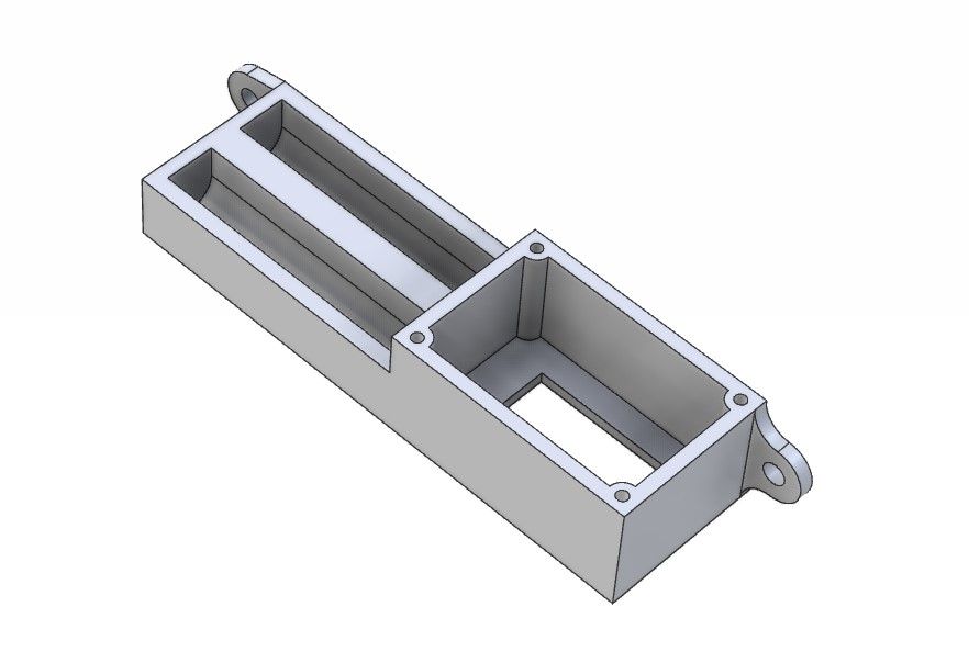
      As we are in the tea room, feel free to discuss the merits or otherwise of this proposal. I have, at least, made a preliminary drawing of the sensor housing which I suggest could be 3D printed. It would need a cut-down version of the pcb designing, but I don't think that is beyond the wit of some of you on here.

      housing

      The overall size of this would be in the region of 20mm x 30mm x 90mm long (plus mounting lugs).

      What does the panel think?

      John

      Advert
      #35974
      John Hinkley
      Participant
        @johnhinkley26699
        #484600
        Frances IoM
        Participant
          @francesiom58905

          there is an article by Mark Noel some years ago along the same lines (he never lets a good bit of amenity centre throwout go to waste!) – think it was in MEW – he looked at how linear and repeatable were the measurements.

          The mechanism used to find X + Y movement is to find the shift between samples of the pattern seen by the small camera chip – dim memories of 16 by 16 2D FFTs ring a bell as cross correlation of the 2 images is required.

          ETA I think it is actually done by lookup table as the small image is thresholded against average of the 256pels to give a 16×16 array of 0s and 1s then this 8bit value is applied as the lower 8bits with the previous 8bits as the upper 8bits to a 64k memory programmed to provide the correct X + Y shifts

          Edited By Frances IoM on 08/07/2020 16:32:53

          #484601
          DC31k
          Participant
            @dc31k

            Have a search on 'ADNS 9800 arduino' for many ideas and working code.

            #484608
            John Hinkley
            Participant
              @johnhinkley26699

              Frances and DC31k,

              Thanks for the info and links. Looks like I've got some reading to do!

              John

              #484610
              Ady1
              Participant
                @ady1

                Had a look at stuff a couple of years ago but was never sure about the accuracy

                Deffo the future though, once someone makes one, 0.1mm would do for most of us

                Edited By Ady1 on 08/07/2020 18:10:15

                #484663
                Frances IoM
                Participant
                  @francesiom58905

                  Found the ref to Mark Noel’s article – MEW March 2014 pp19-21 – he considers the scales that are needed that are needed – possibly the 1st such article ?

                  #484681
                  John Hinkley
                  Participant
                    @johnhinkley26699

                    Frances,

                    Just had a quick look at Mark's article and that is the sort of thinking that I proposed on this very forum the year before. Technology has moved on since then and certainly laser displacement measurement can be in the region of 2000 cpi. I brought the subject up again in case someone wanted pick it up and run with it. Like I said, I don't have the expertise to design and fabricate a suitable pcb, nor, quite honestly, the inclination, at the moment to do so.

                    This is, after all, the tea room, so I'm inviting discussion. I do, however, believe that, if it can be done, there could be a market for small, cheap to produce and easily mounted units that aren't nanometre accurate, but satisfactory for hobby use. I have seen commercially available wired systems on the 'net but at "price on application". That suggests to me that they are in RR territory.

                    John

                    #484699
                    KWIL
                    Participant
                      @kwil

                      JH. Where on the saddle would you mount your box and what surface are you proposing should be the target for reading the movement?

                      #484700
                      John Haine
                      Participant
                        @johnhaine32865

                        John, I'm not sure what units you have seen that are "PoA" and in RR territory? Certainly the M-DRO magnetic units for example are relatively affordable and have a resolution of 5 microns, accuracy must be of the order of hundredths of mm. From some of the postings here there are cheaper mag scales around too, as well as the capacitive ones.

                        I've thought about this approach (in fact I filed a patent on it in 1999), and I know that Heidenhain did some research on the method too. One of the issues with the sensors is that they get their calibration from the accuracy of the camera chip patterning and optical system magnification, neither of which are that well controlled. For their intended application high accuracy and repeatability isn't needed. From what I recall of the "professional metrology" research it was concluded that it would be necessary to have a "scale" on the surface being measured, even if it was just a line etched every mm or so, so not a great improvement on other approaches.

                        #484701
                        Michael Gilligan
                        Participant
                          @michaelgilligan61133
                          Posted by KWIL on 09/07/2020 09:45:30:

                          … what surface are you proposing should be the target for reading the movement?

                          .

                          The ‘camera-based’ mice don’t need a target per se … They compare consecutive images of whatever surface they are seeing … blank paper, cast iron, whatever [anything with more texture than an optically smooth surface]

                          MichaelG.

                          #484705
                          John Hinkley
                          Participant
                            @johnhinkley26699

                            John Haine,

                            I think this was the site I had a quick look at which gave rise to my PoA and RR comment – but I can't be sure because I didn't keep a record of it. Laser sensors

                            As for cost – I just thought that you can pick up an LED mouse for a fiver and a laser one for a bit more. How much a pcb would cost, I've no idea, but people do it in their garden sheds, so it must be doable for not a lot. A bit of programming for the display on a tablet or phone and away you go! Easy, when you say it quickly and haven't the faintest idea what's involved!

                            Michael G. is quite right. I envisaged the camera to "look" at the upper face of the saddle, for example. A strip of metal along the bed of the lathe at the rear would perform the same function. No "pattern" required, or so I understand.

                            John

                            #484706
                            KWIL
                            Participant
                              @kwil

                              Machine DRO Magnetic, Resolution 5 micron, Accuracy +/- 15 micron, so you are somewhere within a band 1.2 thou " wide.

                              #484709
                              Michael Gilligan
                              Participant
                                @michaelgilligan61133
                                Posted by John Hinkley on 09/07/2020 10:24:37:

                                […]

                                Michael G. is quite right. I envisaged the camera to "look" at the upper face of the saddle, for example. A strip of metal along the bed of the lathe at the rear would perform the same function. No "pattern" required, or so I understand.

                                John

                                .

                                The Wikipedia page gives a useful overview: **LINK**

                                https://en.wikipedia.org/wiki/Optical_mouse

                                … but I’m sure I have a good article tucked-away somewhere

                                I may be back later

                                MichaelG.

                                .

                                … and I am back

                                http://tim.cexx.org/?p=613


                                Edited By Michael Gilligan on 09/07/2020 11:06:00

                                #484718
                                KWIL
                                Participant
                                  @kwil

                                  John in first posting mentioned interference with tailstock.

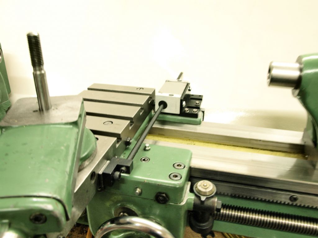
                                  Photo shows minimal interference on a Myford S7 using a commercial (Newall) product.

                                  Early Myford S7 DRO

                                  #484724
                                  Ian P
                                  Participant
                                    @ianp

                                    I know its only my opinion but that does not look like 'minimal' interference with the tailstock, it also looks extremely vulnerable by being bumped into by the tailstock.

                                    At a guess it looks like 30mm or so of lost tailstock travel towards the carriage. I have a much larger lathe and the magnetic scale mounted in the same place as yours only adds 10mm to the carriage width. and its more or less solid ali extrusion so does not mind being hit by a heavy tailstock.

                                    Ian P

                                    #484727
                                    KWIL
                                    Participant
                                      @kwil

                                      20mm to be precise, not much when you have 95mm travel on tailstock even if you are touching , a buffer below the bed level prevents collisions.

                                      Has not caused any difficulties in actual use. If you used a glued/screwed on magnetic strip you would get let less loss of travel. What was the make you used?

                                      I used a similar approach on my M300 Harrison.

                                      Edited By KWIL on 09/07/2020 11:59:49

                                      #484730
                                      John Haine
                                      Participant
                                        @johnhaine32865

                                        John, thanks for that link – those laser sensors use a different principle and are in a different league from the "mouse" type sensors, hence the price. In the "laser mice" I think the laser is used as a more collimated and brighter illumination than the more common LED to getter better precision (and probably speed) – I don't think they really rely on the specific "laser" aspects such as coherence.

                                        I'm not saying that the mouse type approach doesn't have merit, it's just that they don't inherently have tremendous accuracy and will either need a calibrated scale to look at or need individual calibration. In either case it complicates the signal processing which is done in a ready-programmed DSP on-chip.

                                        I believe the magnetic scales (such as the M-DRO ones) have a fairly simple Hall effect sensor to read the periodic magnetic field imprinted on the "scale" – it's still a single chip reader. One of its advantages is that the scale-reader distance is pretty non critical – M-DRO quote 0.1 – 1 mm IIRC – whereas the mouse type will need its "microscope" fairly accurately focused so distance will be critical (Michael can advise I think). So I think there are good reasons why all the medium accuracy DROs haven't just adopted mouse sensors wholesale. Also when you look at the mag sensors they are well packaged for immunity from swarf and suds etc, and the reading surface appears to be an aluminium plate. A mouse type has to have an optical aperture and its lens will be prone to getting mucky and scratched.

                                        Still very interesting devices and I'm sure they have other applications.

                                        #484731
                                        Ian P
                                        Participant
                                          @ianp

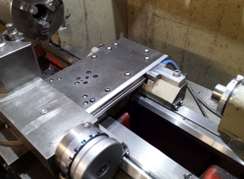
                                          The scale is the magnetic one from Machine DRO

                                          Tapped holes filled with button head screws came with the lathe (Harrison M250) I assume they are not original

                                          Ian P

                                          cross slide dro scale .jpg

                                          #484734
                                          KWIL
                                          Participant
                                            @kwil

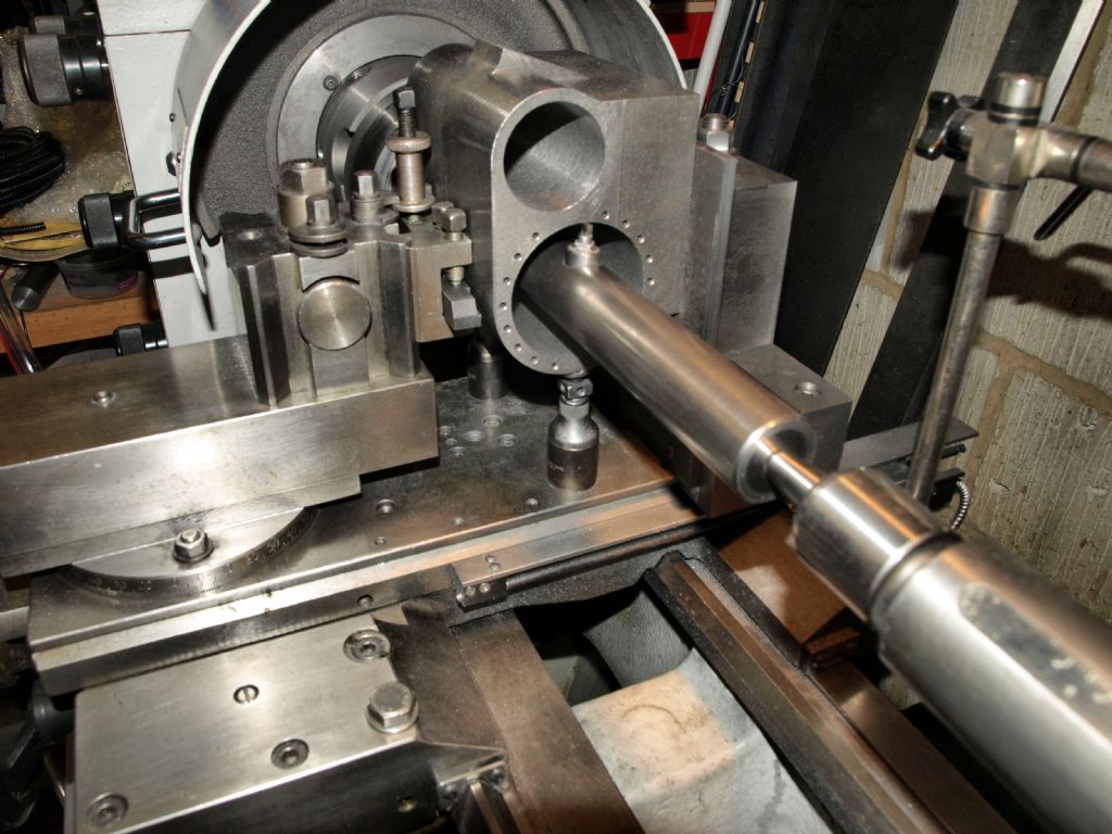
                                            I lost 15mm on the M300 but kept the dovetail edge of the cross slide.Highland/Black5 Main Cylinder

                                            #484738
                                            Ian P
                                            Participant
                                              @ianp

                                              I didn't know the M300 had a dovetailed edge, are there some accessories that use it?

                                              That Newall installation looks good.

                                              I see your cross slide also has tapped holes, the ones on my M250 seem to be in mostly random positions and none really line up with counterbored holes in the (still unused) tee slotted milling table that came with the lathe.

                                              Ian P

                                              #484751
                                              John Hinkley
                                              Participant
                                                @johnhinkley26699

                                                Oh well. Another seven years on the back burner, then!

                                                John

                                                #484753
                                                KWIL
                                                Participant
                                                  @kwil

                                                  Sorry John, we seem to have hijacked the thread, not intentionally, just lost sight of the discussion.

                                                  #484755
                                                  KWIL
                                                  Participant
                                                    @kwil

                                                    Ian, accessories? I guess so, but I made my own.

                                                    A rear "post" that supports a drilled plate that allows for both the main bore and valve bore of the cylinder block (7.25" guage) to be line bored, actually jig pinned for exact copies. Shows clearly in the photo, boring bars fitted with Microbore adjustable tooling.

                                                    #484759
                                                    Ian P
                                                    Participant
                                                      @ianp

                                                      I know this is prolonging this off-topic discussion, but is the rear 'post' bolted straight down to the cross slide or does it in some way locate on the side dovetails?

                                                      Either way the cylinder block looks a lovely bit of work.

                                                      After seeing yours, I must make a swarf tray to fit between the ways, one thing that I noticed when I changed from a Boxford lathe was that cleaning up (or finding dropped parts!) was much more of a pain.

                                                      I dont have any microbit tooling but its nice stuff.

                                                      Ian P

                                                    Viewing 25 posts - 1 through 25 (of 32 total)
                                                    • Please log in to reply to this topic. Registering is free and easy using the links on the menu at the top of this page.

                                                    Advert

                                                    Latest Replies

                                                    Home Forums The Tea Room Topics

                                                    Viewing 25 topics - 1 through 25 (of 25 total)
                                                    Viewing 25 topics - 1 through 25 (of 25 total)

                                                    View full reply list.

                                                    Advert

                                                    Newsletter Sign-up