I think there are truths in both our observations.
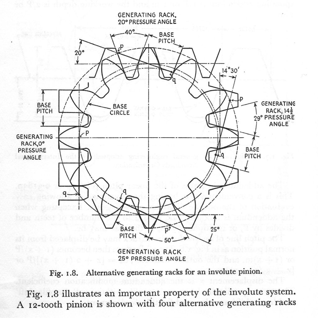
Note that for the 0-degree rack the base circle and the PCD are the same.
None of the illustrated generated gears have thr PCD half way up the tooth as you would expect for a 'standard' gear.
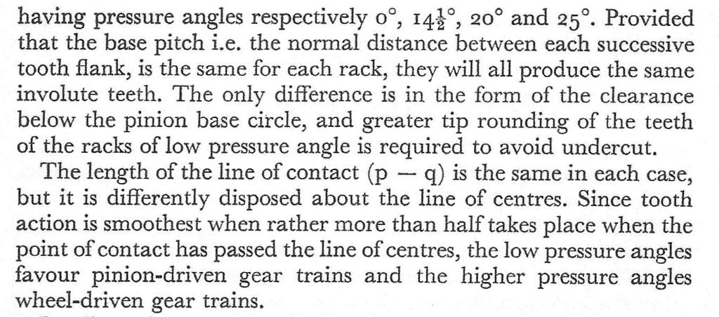
In other words they are ALL examples of gears cut for an increased centre distance. This is normal practice when cutting gears with low tooth counts, you increase the separation to reduce undercutting.
It's well known that involute gears are tolerant of errors in PCD and spacing. The diagram shows why – you can adjust the tooth profile bay varying the cutter infeed.
It also suggests that, when making my jovilabe gears on 'incorrect' PCDs, I could have improved the tooth profiles by using extra or reduced feed – something i discovered 'by accident' without realising what was happening. Some of my gears had too-thin teeth (I should have reduced infeed) and some chunky gears were improved by a second pass with a little more infeed.
I may be misreading the diagram, but it appears to suggest that if you want well-formed oversize gears then reduce the infeed or, ideally, use an over-length cutter.
My 'rack formed' gears will all mate with a rack, and each-other for the same infeed but varying PCDs. What I hadn't realised is that well-formed and 'pretty' looking gears of varying PCD can be cut with the rack form.
There is obviously a limit, however, otherwise you would be able to use a rack of any pressure angle to cut a rack with a different pressure angle.
So where is the limit? My guess is that the straight-sided rack gives us a clue, it's ends are bevelled to provide clearance – does the principle fail when the required PCD becomes equal to or less than the diameter of the base circle? Increasing the angle, perhaps the fail point is when the PCD equals or exceeds the OD?
I'm sure Andrew J. will be long in a while to explain it all for us 
Neil
duncan webster 1.


