help identifying lathe

Advert

help identifying lathe

Home Forums Manual machine tools help identifying lathe

Viewing 25 posts - 1 through 25 (of 27 total)
  • Author
    Posts
  • #550605
    James Tregaskis
    Participant
      @jamestregaskis13908

      hi,

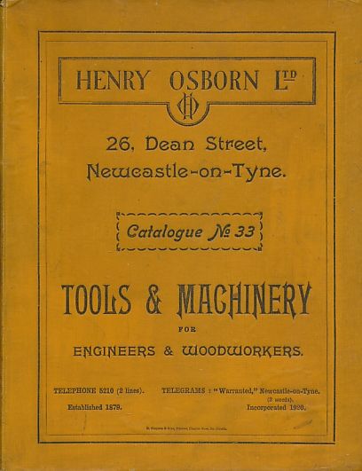
      I need help in identifying a lathe that I have obtained. I think it is built by Myford in the early 50's, but I am not sure. The only identifying mark is the label marked "Osborn Ltd. Newcastle upon Tyne".
      I have prepared a private web-page, please have a look at the photographs of it at the following link:
      https://www.tregaskis.org/help-needed-to-identify-this-lathe/
      In order to open the link you have to put in the password: myford

      I am looking for a suitable 4 jaw and 3 jaw chucks also a suitable electric motor to drive it.

      Many thanks,
      James

      Advert
      #14295
      James Tregaskis
      Participant
        @jamestregaskis13908

        new aquisition

        #550606
        Lee Rogers
        Participant
          @leerogers95060

          Not sure that's a Myford. Have a look on the lathesuk website there is a big section on ML 1/2/3/and 4. That brass pulley is astonishing. You need to add a countershaft to your shopping list.

          #550613
          Peter Bell
          Participant
            @peterbell11509

            Cannot help with the lathe but Henry Osborn sold tools and general engineering supplies from Percy Street in Newcastle-upon-Tyne when I knew them in the 60's. Very helpful people when I wanted some pulleys. Seem to remember them moving there from elseware but when I knew them looks like they were a shadow of there former selves.

            Peter

            r7322b.jpg

            r7322b-1.jpg

            #550617
            Roderick Jenkins
            Participant
              @roderickjenkins93242

              Looks like a (modified) RandA/ Winfield **LINK**

              According to the RandA page these were sold my Myford in the 1930s. Winfield are always a good bet for identifying these small basic British lathes, they seem to have made a lot of models for badge engineering.

              Cheers,

              Rod

              #550653
              James Tregaskis
              Participant
                @jamestregaskis13908
                Posted by Lee Rogers on 20/06/2021 17:59:42:

                Not sure that's a Myford. Have a look on the lathesuk website there is a big section on ML 1/2/3/and 4. That brass pulley is astonishing. You need to add a countershaft to your shopping list.

                Lee thank you for that, I need to know more… countershaft, need to research…. all comments/links/examples please guys, I need help to get this machine back in action!

                #550656
                James Tregaskis
                Participant
                  @jamestregaskis13908
                  Posted by Roderick Jenkins on 20/06/2021 19:18:25:

                  Looks like a (modified) RandA/ Winfield **LINK**

                  According to the RandA page these were sold my Myford in the 1930s. Winfield are always a good bet for identifying these small basic British lathes, they seem to have made a lot of models for badge engineering.

                  Cheers,

                  Rod

                  Dear Rod THANK YOU! Wow that's really good of you… I can dig deeper now. Still need some ideas/advice on powering it and sources to get backplate and chuck(s) -…… 3" yes?

                  #550679
                  Ady1
                  Participant
                    @ady1

                    Hope its ok to put it up

                    The lump of brass that made the headstock pulleys would probably cost as much as the lathe on ebay nowadays

                    Edited By Ady1 on 21/06/2021 08:04:59

                    #550809
                    James Tregaskis
                    Participant
                      @jamestregaskis13908
                      Posted by Ady1 on 21/06/2021 08:03:25:

                      Hope its ok to put it up

                      The lump of brass that made the headstock pulleys would probably cost as much as the lathe on ebay nowadays

                      Edited By Ady1 on 21/06/2021 08:04:59

                      Yeah, its fine! I am possibly going to fit a sewing machine motor to run it… thoughts anyone? Maybe not enough grunt but with pulley ratio, it might be OK?

                      #550810
                      not done it yet
                      Participant
                        @notdoneityet

                        Wattage? If it is the typical domestic machine, no way. Likely enough to turn the lathe but not to cut.

                        #550820
                        James Tregaskis
                        Participant
                          @jamestregaskis13908
                          Posted by not done it yet on 21/06/2021 22:06:47:

                          Wattage? If it is the typical domestic machine, no way. Likely enough to turn the lathe but not to cut.

                          OK, what spec motor should I aim for?

                          #550821
                          not done it yet
                          Participant
                            @notdoneityet

                            I wouldn’t suggest any specific motor. Your sewing machine motor may be adequate, particularly if an industrial machine. Depends, really, on the Wattage, as I enquired above.

                            #550822
                            James Tregaskis
                            Participant
                              @jamestregaskis13908
                              Posted by not done it yet on 22/06/2021 07:01:16:

                              I wouldn’t suggest any specific motor. Your sewing machine motor may be adequate, particularly if an industrial machine. Depends, really, on the Wattage, as I enquired above.

                              Yes, of course, thank you; I meant the specification, not any specific motor; i.e. power/wattage would suit?


                              Edited By James Tregaskis on 22/06/2021 07:12:20

                              Edited By James Tregaskis on 22/06/2021 07:30:22

                              Edited By James Tregaskis on 22/06/2021 07:30:48

                              Edited By James Tregaskis on 22/06/2021 07:32:43

                              #550825
                              Ady1
                              Participant
                                @ady1

                                If you're not hogging a lot of metal then a 0.25kw motor will run a well adjusted machine and cut fine swarf

                                Other things to consider are duty cycle, will the motor run non-stop for 30-mins plus without blowing up?

                                and RPM, your lathe will probably be about 500-700 max with solid bearings so a 4000RPM sewing motor will need to be restricted

                                #550827
                                James Tregaskis
                                Participant
                                  @jamestregaskis13908

                                  I have a pair of these motors, maybe I could use one of them. I have the O-drive controller and position sensor as well and a 24V PSU… maybe this would work?

                                  https://odriverobotics.com/shop/odrive-custom-motor-d5065

                                  https://docs.google.com/spreadsheets/d/12vzz7XVEK6YNIOqH0jAz51F5VUpc-lJEs3mmkWP1H4Y/edit#gid=0

                                  Edited By James Tregaskis on 22/06/2021 07:33:55

                                  #550860
                                  Emgee
                                  Participant
                                    @emgee

                                    Hi James

                                    If you have an industrial sewing machine motor of at least 250W output power it may be suitable for your lathe, the type I am thinking of were underslung from the machine and usually incorporated a manual brake at the NDE, some of these were 1/2HP and more.

                                    My first lathe was a Portass which was similar in design to yours, when bought it was fitted with a 1/3HP motor but I changed it to a 1/2HP because of the duty rating of the smaller motor, probably better if you are buying a motor to go for a 1/2HP in the first place.

                                    As said speed may also be something to consider, especially if you are not fitting a countershaft between motor and spindle. (a countershaft has pulleys to match the motor pulleys but the small pulley on the motor is belted to the large c/shaft pulley so giving a speed reduction, power to the lathe is taken from one of the other c/shaft pulleys to suit the spindle speed required)

                                    You could of course go the VFD route using a dual voltage (220/400) 3 phase motor, IMO a .37kW 4 pole would be suitable.

                                    The Vee belt showing looks very long, perhaps it was driven from an overhead shaft.

                                    Emgee

                                    #550878
                                    Howard Lewis
                                    Participant
                                      @howardlewis46836

                                      If from the 50s, would be a ML7, and it isn't. The ML7 was launched in 1947.

                                      Not a predecessor Myford such as the ML1,2,3 or 4. (The headstock and banjo are not like those, and the bed iooks to be too long. ).

                                      The photos don't show the bed form, whether flat or dovetaill, which will also help in identification..

                                      For chucks, you need to measure the diameter and pitch of the thread on the Mandrel, and the register for the chuck..

                                      A British lathe of that vintage is likely to have a Whitworth form threads, and have Imperial dimension..

                                      It is likely, therefore that you will need to make up adaptors to convert your thread/register to one that is easily available. The 1.25 x 12 tpi of Myford would seem to be the most likely, IF the sizes allow.

                                      It may be worth sacrificing an inch or so of bed space to use such an adaptor.

                                      Here, you are in the Catch 22 situation of needing a chuck to hold the material while you do the machining.

                                      Sounds like you need to find your ,local Model Engineering Society and throw yourself on the mercy of someone to make the adaptor for you.

                                      Where are you located?

                                      Once you have an adaptor, you could leave in place so that subsequently Myford fitting chucks and faceplates, etc can be fitted.

                                      It would be worth spending some time checking your changewheels, to see what you have.

                                      Hopefully, a complete set, probably incrementing from something like 20T in 5T steps up to 65, 70 or even 80T

                                      You can calculate the DP of the gears by measuring OD and counting the teeth. It is possible that the Pressure Angle will be 14.5 on a machine of that age, rather than the 20 degrees favoured more recently.

                                      That would allow you to set up for power feeds or screwcutting, as and when you feel the need and have the confidence.

                                      Howard.

                                      #550903
                                      James Tregaskis
                                      Participant
                                        @jamestregaskis13908

                                        Hi Howard, thanks for a very helpful reply… and I’m not at home so I can’t get hold of my callipers but it is 12 TPI 1 inch diameter so it’s probably Whitworth. Everything looks pretty straight and I have a good set of cogs I’ll go through them in due course. I’m already getting help from a kind person on this site I don’t want to ask too much of him. Hopefully I will get some kind soul to make me an adapter. It looks quite well cared for and I am now figuring Out how to best power it. I have an O-Drive board and skateboard motor; the controller which is pretty tough and is actually programmable to run the lathe. The kind of person who is helping me already has sourced me a chuck which will need an adapter.

                                        It is so nice here on this forum because everyone is helping newbies like me, please keep the comments coming I am devouring them! Cheers,

                                        james

                                        #550921
                                        SillyOldDuffer
                                        Moderator
                                          @sillyoldduffer

                                          About 1/3HP – 1/2HP should be fine. Next step is to sort out the speeds, on a lathe with those plain bearings, I'd be thinking 1000rpm tops. Maybe 400rpm and 100rpm from the slower pulleys unless a variable speed motor is used.

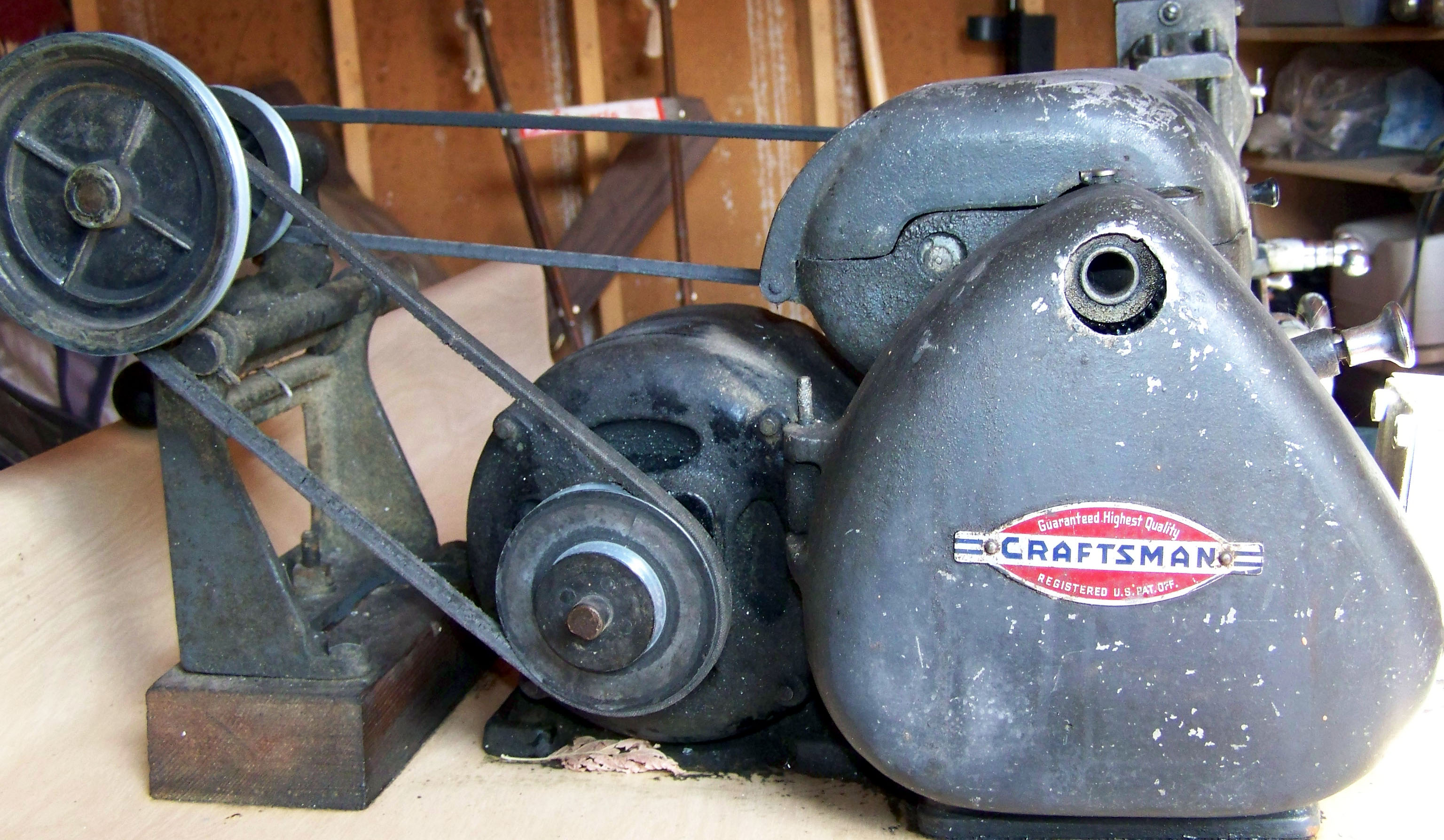
                                          When the lathe was new, it was probably driven from a countershaft like this example from lathes.co.uk (recommended website!)

                                          The motor would have been a fixed speed induction type, too fast for the lathe connected directly. So they're geared down by a belt to the countershaft (left of pic), which drives another three-way pulley, which your long belt would attach to, giving a choice of 3-speeds by moving the belt between pulley pairs.

                                          Your O-Drive motor isn't one I'd naturally think of using, but hey – you have one with controller and PSU. Flat out the motor is too fast and powerful for the lathe, so be very careful to keep it throttled well back. Being overkill, I think it would work well driving the lathe directly, assuming the power supply is man enough. (The motor is rated 1800W, max 8500rpm, from 32V @ 65A with 'extremely good forced air cooling'.) I'd set the motor up for direct drive and try cutting metal, keep an eye on the speed with a cheap ebay rpm meter. Check motor temperature frequently at first: it's allowed to get warm, but not hot! If it shows any signs of overheating, cool it with an electric fan.

                                          The spec says the motor delivers about 1/3 output with ordinary cooling, which should be 'good enough' for that size of lathe.

                                          Dave

                                          #550932
                                          James Tregaskis
                                          Participant
                                            @jamestregaskis13908
                                            Posted by SillyOldDuffer on 22/06/2021 18:55:35:

                                            About 1/3HP – 1/2HP should be fine. Next step is to sort out the speeds, on a lathe with those plain bearings, I'd be thinking 1000rpm tops. Maybe 400rpm and 100rpm from the slower pulleys unless a variable speed motor is used.

                                            When the lathe was new, it was probably driven from a countershaft like this example from lathes.co.uk (recommended website!)

                                            The motor would have been a fixed speed induction type, too fast for the lathe connected directly. So they're geared down by a belt to the countershaft (left of pic), which drives another three-way pulley, which your long belt would attach to, giving a choice of 3-speeds by moving the belt between pulley pairs.

                                            Your O-Drive motor isn't one I'd naturally think of using, but hey – you have one with controller and PSU. Flat out the motor is too fast and powerful for the lathe, so be very careful to keep it throttled well back. Being overkill, I think it would work well driving the lathe directly, assuming the power supply is man enough. (The motor is rated 1800W, max 8500rpm, from 32V @ 65A with 'extremely good forced air cooling'.) I'd set the motor up for direct drive and try cutting metal, keep an eye on the speed with a cheap ebay rpm meter. Check motor temperature frequently at first: it's allowed to get warm, but not hot! If it shows any signs of overheating, cool it with an electric fan.

                                            The spec says the motor delivers about 1/3 output with ordinary cooling, which should be 'good enough' for that size of lathe.

                                            Dave

                                            ,Hi Dave,

                                            I will get a Nema 23 metal faceplate to hold the motor in place (not the 3D printed enclosure I have at present). I may need someone to machine me a brass V-belt pulley for the O-Drive shaft, I only have the ribbed kind at the moment. The O-Drive is really too 'good' for the lathe but I will opt for something more conventional longer term as I don't want to tie up the controller board for this application… The O-Drive and this brushless motor is very powerful and can do much more than this job, e.g. see this short video!

                                            #550979
                                            Nicholas Farr
                                            Participant
                                              @nicholasfarr14254
                                              Posted by James Tregaskis on 22/06/2021 15:29:20:

                                              Hi Howard, thanks for a very helpful reply… and I’m not at home so I can’t get hold of my callipers but it is 12 TPI 1 inch diameter so it’s probably Whitworth. Everything looks pretty straight and I have a good set of cogs I’ll go through them in due course. I’m already getting help from a kind person on this site I don’t want to ask too much of him. Hopefully I will get some kind soul to make me an adapter. It looks quite well cared for and I am now figuring Out how to best power it. I have an O-Drive board and skateboard motor; the controller which is pretty tough and is actually programmable to run the lathe. The kind of person who is helping me already has sourced me a chuck which will need an adapter.

                                              It is so nice here on this forum because everyone is helping newbies like me, please keep the comments coming I am devouring them! Cheers,

                                              james

                                              Hi James, if the nose is 1 inch x 12TPI then it is probably 1 inch UNF, (not NF, which is 14TPI) which is what my father's old RandA lathe is and you may have to get a blank backplate or two and machine them to fit any chucks you want to use. My father's old RandA lathe worked happily enough with a 1 / 4 HP induction motor via a counter shaft similar to this RandA page 2

                                              A 1 / 3 HP induction motor or something equivalent should be about the largest you would need though I would think.

                                              Regards Nick.

                                              #551007
                                              Howard Lewis
                                              Participant
                                                @howardlewis46836

                                                If it may be a R and A then look at the Lathes UK website, for R and A lathes. There should be a lot of useful information there.

                                                Howard

                                                #551855
                                                James Tregaskis
                                                Participant
                                                  @jamestregaskis13908
                                                  Posted by Nicholas Farr on 23/06/2021 09:41:44:

                                                  Posted by James Tregaskis on 22/06/2021 15:29:20:

                                                  Hi Howard, thanks for a very helpful reply… and I’m not at home so I can’t get hold of my callipers but it is 12 TPI 1 inch diameter so it’s probably Whitworth. Everything looks pretty straight and I have a good set of cogs I’ll go through them in due course. I’m already getting help from a kind person on this site I don’t want to ask too much of him. Hopefully I will get some kind soul to make me an adapter. It looks quite well cared for and I am now figuring Out how to best power it. I have an O-Drive board and skateboard motor; the controller which is pretty tough and is actually programmable to run the lathe. The kind of person who is helping me already has sourced me a chuck which will need an adapter.

                                                  It is so nice here on this forum because everyone is helping newbies like me, please keep the comments coming I am devouring them! Cheers,

                                                  james

                                                  Hi James, if the nose is 1 inch x 12TPI then it is probably 1 inch UNF, (not NF, which is 14TPI) which is what my father's old RandA lathe is and you may have to get a blank backplate or two and machine them to fit any chucks you want to use. My father's old RandA lathe worked happily enough with a 1 / 4 HP induction motor via a counter shaft similar to this RandA page 2

                                                  A 1 / 3 HP induction motor or something equivalent should be about the largest you would need though I would think.

                                                  Regards Nick.

                                                  Hi Nick,

                                                  I anticipated the need to provide a decent power train for my lathe; I found a (used!) Myford Vee-pulley with 4 diameters going for a song on eBay, it has a key fitting on 3/4" I.D.

                                                  I ordered a 3/4" round steel rod and I will get some pillow blocks to support it. I was admiring the countershaft arrangement and want to build something like the one belonging to your father, I just wondered if there are any drawings available?

                                                  Any info on this setup would be great.

                                                  ALSO…..

                                                  Possibly too many questions here below, but I really would be grateful if anyone feels inclined to answer?

                                                  * I have a load of gears that came with it but the I.D. is smaller than on the lathe… I wonder if they were from something else?

                                                  * Also there is a lever at the back, presumably to do forward/reverse but it 'locks up' the transmission when engaged, I do not think it is set up right, something is wrong here. Its not very clear in the photos but both cogs (either side of the lever) engage with cogs the other side at the same time, hence the lockup situation. Maybe I should remove on of the cogs? I can't figure it out.

                                                  * You will see it has a mechanism for operating the main screw with an escapement type arrangement. I have not seen this on other lathes. Any other photos/examples/notes on this mechanism?

                                                  *what type of tool holder accessory is best to use to replace the crude toolholder there is currently? I think I might be able to replace the vertical threaded rod to a longer one and get something from Banggood?

                                                  e.g. https://www.banggood.com/Machifit-250-000-Cuniform-GIB-Type-Quick-Change-Tools-Kit-Tool-Post-250-001-010-Tool-Holder-for-Lathe-Tools-p-1434251.html?akmClientCountry=GB&p=9B120818168716201801&custlixnkid=720029&cur_warehouse=UK&ID=515563

                                                  * One more thing, I tried getting the main shaft out but am a bit frightened to use much force on removing existing cogs… anyone?

                                                  Edited By James Tregaskis on 29/06/2021 17:33:10

                                                  #551862
                                                  Howard Lewis
                                                  Participant
                                                    @howardlewis46836

                                                    The lever on the back that locks the transmission is not to reverse, but most probably to engage back gear. the reason that everything locks is that you have effectively engaged two gears, of different ratios at the same time.

                                                    You need to find how to disengage the bull wheel (The gear that is locked to the pulley ) so that the drive can be pulley to small gear pinion, to large gear on back gear shaft thence to small gear on back gear shaft and back ton the bull wheel and mandrel..

                                                    Most probably a grubscrew in the bottom of one of the vees in the pulley.

                                                    Probably safest to remove the grubscrew completely and put it in a safe place, rather than leave it in and chance it being thrown out at some time when back gear is being used.

                                                    Back gear will reduce the speed of the mandrel by a factor of about 6, and provide extra torque.

                                                    It is a very useful feature when working, or screw cutting upto a shoulder, in that it gives you more time to disengage the feed, or stop the mandrel by slackening the belt. Saves a lot of damaged tools and workpieces, ,believe me!

                                                    The mechanism to reverse the feed, probably by the Leadscrew will be the tumbler reverse. This is two identical pinions, meshed together and mounted on a lever which allows one pinion to drive the geartrain directly, or when the lever is moved, via the second gear (Which acts as an Idler and so reverses the direction of rotation of the gear train relative to the mandrel.

                                                    My preference is for the "old fashioned" 4 way toolpost. Reputed to be more rigid that a QCT. Not having one, cannot confirm or deny. But the more rigid the tool set up, the better things will be from the point of surface finish and accuracy.

                                                    Biased, 'cos I have one at the front and another at the back!

                                                    For a lathe of that age, HSS would be my advice on tooling. You learn how to grind tools, is cheaper than carbide. (The lathe was designed before carbide tooling became common place, so will lack the speed and rigidity to get the best out of it. Intended for heavy industrial machines where time is money )

                                                    My favourite HSS tool is the Tangential Turning Tool, either home made, (MEW has published at least two designs, in the past ) or the Diamond tool from Eccentric Engineering. With only one face to grind, sharpening is quick and easy.

                                                    A 1/4" toolbit cost about the same as a carbide insert and will outlast a single carbide insert. Plus, as I keep saying, you can regrind at 8:00 on a Saturday night, when a chipped carbide tip ceases to be of any use.

                                                    Before anyone complains of ignorant bias, I also use carbide tips, for roughing, boring and screwcutting!

                                                    The "escapement type arrangement" looks to be a detent for indexing, using a changewheel to provide the means of dividing.j

                                                    HTH

                                                    Howard

                                                    #551863
                                                    Nicholas Farr
                                                    Participant
                                                      @nicholasfarr14254

                                                      Hi James, those gears as if they are Drummond screw cutting change gears for the leadscrew with the two holes in them for driving them. The gears that are locking together are backgears for screw cutting, when in use, you need to release the grub screw on the V pulley, to allow that to turn on the spindle, it will then drive the spindle at a slower speed through those back gears.

                                                      Regards Nick.

                                                    Viewing 25 posts - 1 through 25 (of 27 total)
                                                    • Please log in to reply to this topic. Registering is free and easy using the links on the menu at the top of this page.

                                                    Advert

                                                    Latest Replies

                                                    Home Forums Manual machine tools Topics

                                                    Viewing 25 topics - 1 through 25 (of 25 total)
                                                    Viewing 25 topics - 1 through 25 (of 25 total)

                                                    View full reply list.

                                                    Advert

                                                    Newsletter Sign-up