GEC Motor Bearings for Lathe Motor

Advert

GEC Motor Bearings for Lathe Motor

Home Forums Manual machine tools GEC Motor Bearings for Lathe Motor

Viewing 25 posts - 1 through 25 (of 51 total)
  • Author
    Posts
  • #373976
    Andy Carlson
    Participant
      @andycarlson18141

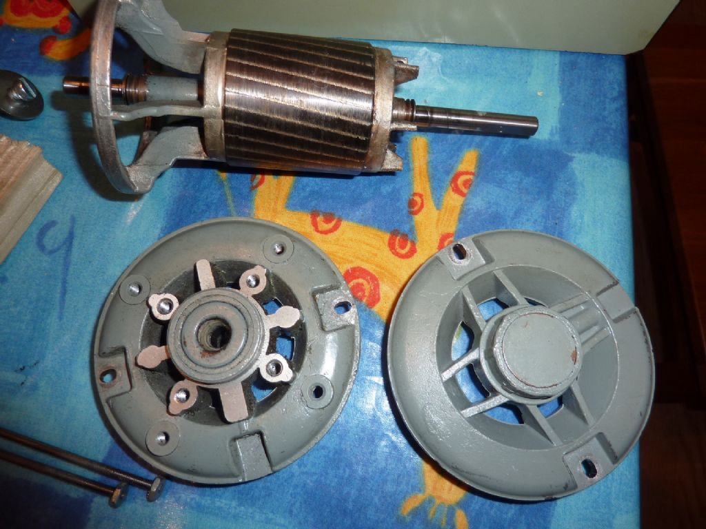
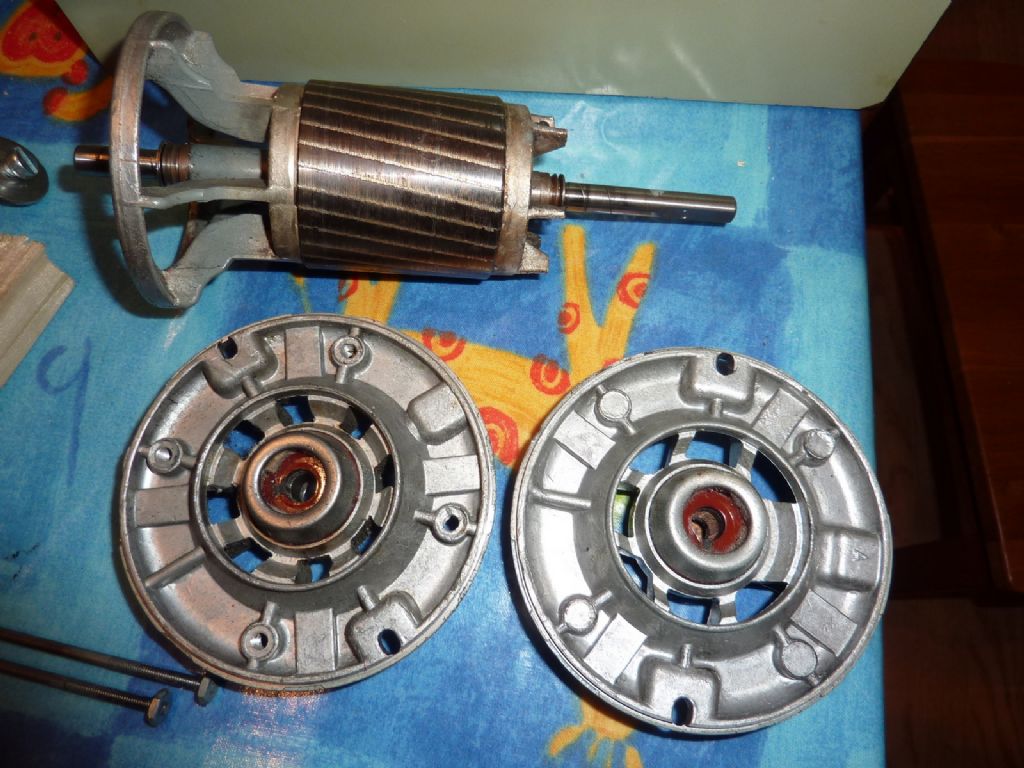
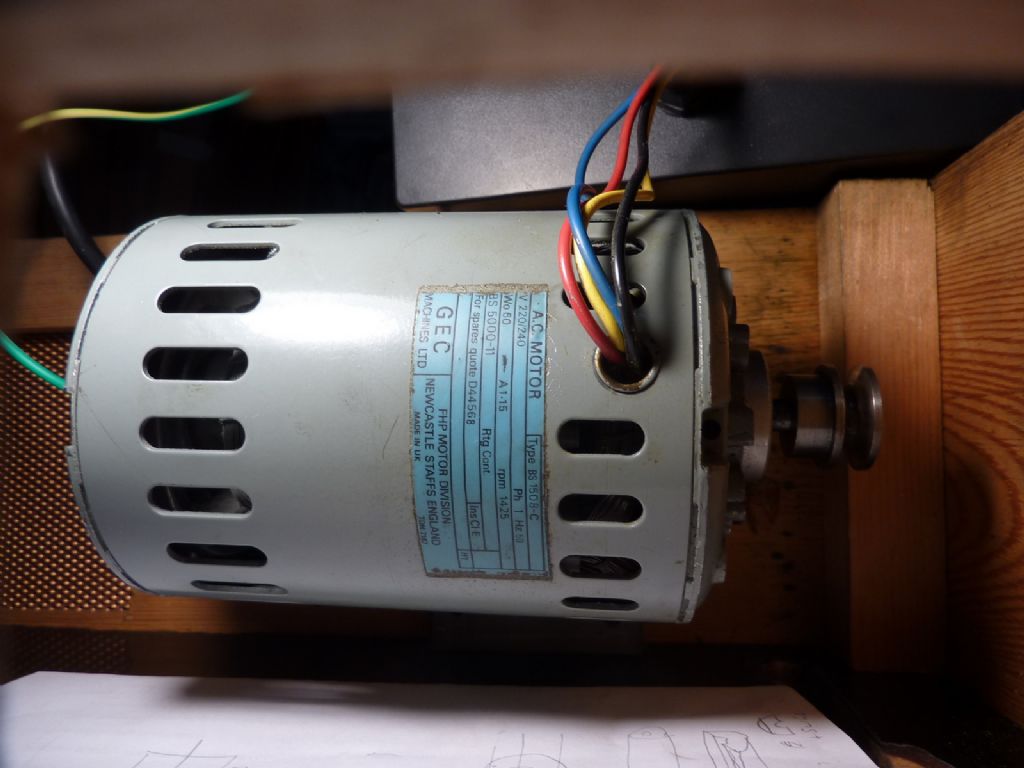
      This single phase AC motor (see photos) was supplied with Cowells lathes in the late 1970s (and perhaps later).

      The motor is GEC 'type BS 1508-C, 1425 rpm, for spares quote D44568' if anyone wants the blurb from the sticker.

      The bearings appear to be worn sufficiently for the rotor to rub on the stator when the drive belt to the lathe is not tight.

      I'd like to replace them but how to get them out is not clear to me. I'm hoping that someone here has successfully done something similar.

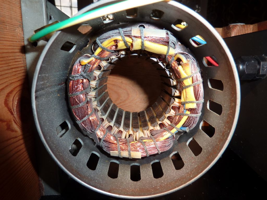
      The motor seems to be a pretty simple affair with no slip rings or commutator involved. The alloy ends house the bearings and are secured by two (2BA?) threaded rods that go right through the casing. With the nuts undone it is easy to take off the ends and pull out the rotor.

      The bearings seem to be plain (bronze I guess) but they are enclosed by what look like pressed steel caps both on the outside and inside ends. There seems to be some wicking material surrounding them and a wick in contact with the motor shaft. The shaft has a spiral groove presumably to persuade the oil into the bearings. A (tufnol?) part surrounds the shaft inside the end caps on the 'indoors' end.

      Can anyone advise on how to get the bearing housings apart without causing damage please?

      I suspect that a previous owner has turned one of the ends through 180 degrees such that the unworn side of the bearing takes the load of the drive belt. This does stop the rotor from rubbing on the stator as long as the belt is tight but it can still make grating noises when starting and I'm not happy with it as a long term answer.

      Thanks.

      Andy

      p1060543.jpg

      p1060542.jpgp1060540.jpgp1060507.jpg

      Advert
      #13306
      Andy Carlson
      Participant
        @andycarlson18141
        #373982
        Michael Gilligan
        Participant
          @michaelgilligan61133

          Wow, Andy !!

          I've never seen motor bearings that worn. … Surely the belt must have been much too tight.

          I don't know how closely the pictures here resemble your bearings, but they look similar enough to give you some clues: **LINK**

          https://www.scandor.se/Filer/PermawickBrochure.pdf

          MichaelG.

          #373985
          Mark Rand
          Participant
            @markrand96270

            If you have a working lathe other than the Cowells one, it may be a good idea to bore the end bells so that you can replace the original bronze bearings with ball bearings. You'll only need to do it once.

            I say this from having had problems repairing and replacing plain bearings on FHP motors. Even self aligning ball bearings are quite cheap in the sizes needed if the alignment of the end bells isn't certain.

            #373988
            Speedy Builder5
            Participant
              @speedybuilder5

              Looks to me that the outside windings have fried a bit, worthwhile checking their resistance/ possible leak to earth.

              #373994
              IanT
              Participant
                @iant

                Hi Andy,

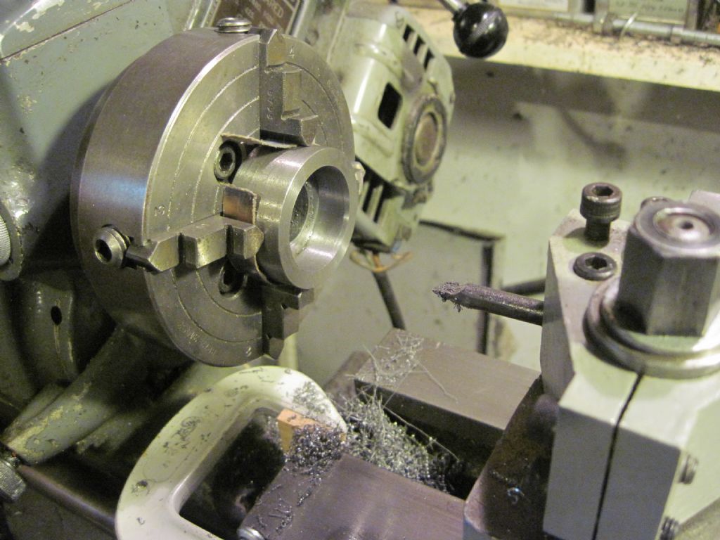
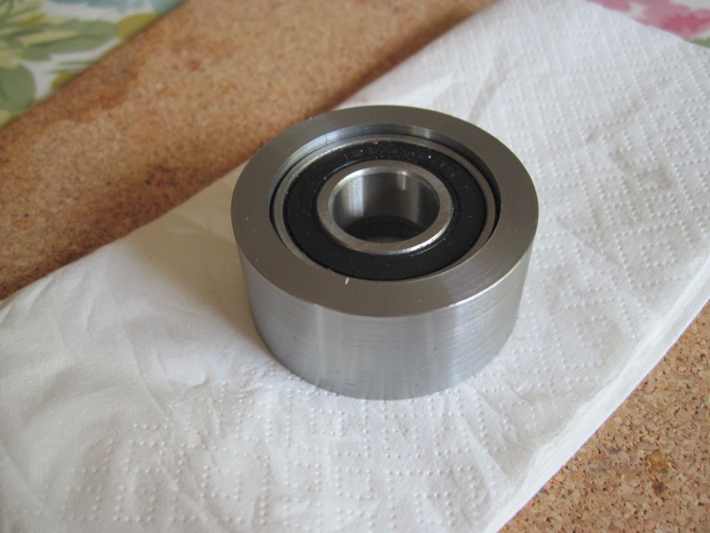
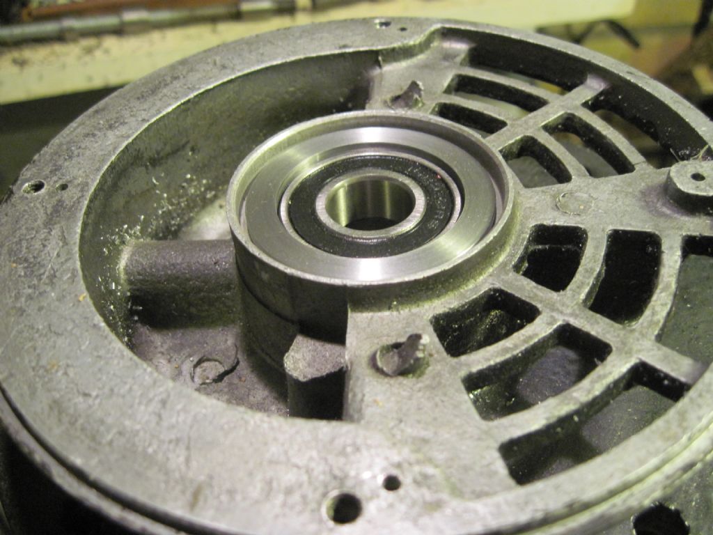
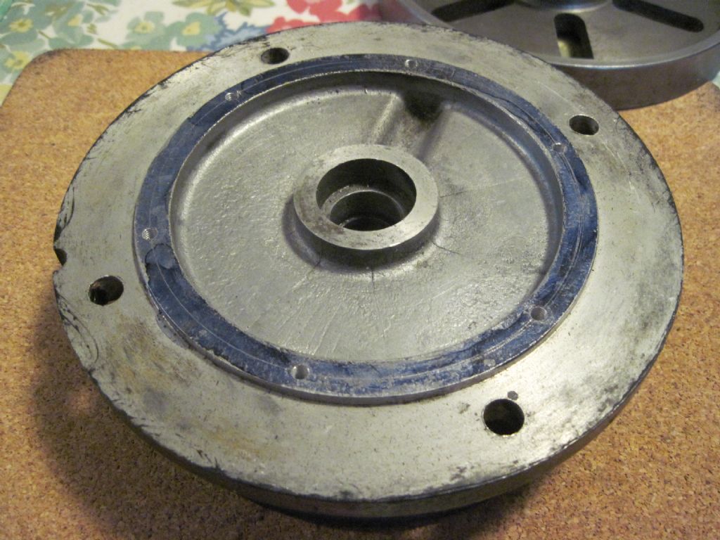
                I'm afraid I could not really see your bearings that clearly but I've had a similar problem with very badly worn motor bearings and the associated motor spindle. I believe my original bearings are called 'shell' bearings (very thin, hard split bearings sat within a felt liner that acts as an oil reservoir). I couldn't remove them, so finally I just bored them completely out. Fortunately the die-cast end bell had enough meat to enable a mild steel 'spacer' to be fitted. The spindle was very badly scored – so this part was turned down between centres to the same diameter as the keyed part of the shaft. I then purchased a sealed bearing, made the liner fit its OD – with the ID sized to hold the spindle. Started assembling the whole thing this pm – and have just loctited the new bearing assembly into the end-bell. The other end bell bearing seems OK but it will get the same treatment if it's not.

                The photos below should give you the general idea.

                As it happens Abom79 has just done a very similar thing for his K&T motor – although he used a cast iron liner that is apparently commonly available for this purpose (but he's in the US). My motor needed a custom solution but either way, hopefully (as Mark has already suggested) this approach will help solve your problem.

                See this YouTube for the Abom79 details: https://www.youtube.com/watch?v=u86tX-w3Z58

                Good luck!

                Regards,

                IanT

                img_5073.jpg

                img_5080.jpg

                img_5076.jpg

                #373998
                Clive Foster
                Participant
                  @clivefoster55965

                  Many years ago I changed the bearings on what, from memory, was motor of similar construction. As I recall it careful inspection showed a way to prise off the steel caps without wrecking things. Most likely it took two or three inspections before the penny dropped. A home made expanding puller device got the bearings out. Turned out to be a standard oilite size in my case. Which I actually had in stock from a "mystery bargain box of useful stuff" purchase.

                  Don't know what the expanding puller device was but these days I'd probably use a large expanding concrete anchor stud (Rawlstud) with a multi-slotted (think ER collet style) alloy tube to fill the gap and improve grip. Stack of O-rings on a stud with taper edged washers in between also makes a good expanding gripper but needs more work to make and covers a much smaller size range. Better grip tho'. Tube and nut on the spare screw or hammer and drift on the end both work fine.

                  Drop the housing in a bucket of boiling water for a few minutes to expand things before trying to extract the bearings. Makes big difference as the fit is generally not very tight. Presumably to avoid risk of pinching bearings down below nominal size. Have had similar arrangements, not motor bearings, simply pull out by hand after getting up to temperature. So don't go too enthusiastic on the expander to start with.

                  Clive.

                  PS Looking at the excellent post from IanT immediately above there are clearly at least two methods of fattening plain bearings into a motor of that general style.  Which does make life harder.

                  Edited By Clive Foster on 30/09/2018 21:56:31

                  #373999
                  Andy Carlson
                  Participant
                    @andycarlson18141

                    Thanks for the posts so far. The PDF is interesting but I suspect a lot more modern than my motor. Interesting that they are still trying to flog plain bearings for similar sized motors though.

                    My other lathe is a Unimat DB/SL so it would not be able to swing the alloy ends of the GEC motor.

                    I didn't notice any sign of thermal damage to the windings when poking around with a lamp in there. The photo was done with flash which can make things loook a bit odd. Certainly the motor does not upset the RCD on our ring main… which plenty of other domestic appliances (mostly steam irons) have managed to do.

                    I'm reluctant to try anything too risky or irreversible because the motor does actually work and the lathe has already done plenty of good work. Having had a look inside now I'm also less worried that it might chew through something carrying 240V.

                    I was rather hoping that, being an old design, there would be a straightforward way to replace the bearings 'like for like' (after all the label does seem to suggest that spare parts were obtainable back in the day).

                    Regards, Andy

                    #374004
                    Andy Carlson
                    Participant
                      @andycarlson18141

                      A few more posts while I was writing mine. Thanks again. I will give the 'expanding puller' thing some thought and will have a rummage through some more civil engineering type bolts to see if anything can be pressed into service. This seems like the type of approach where I could bug out and just tap the cover back on if I wasn't happy with the way things were going.

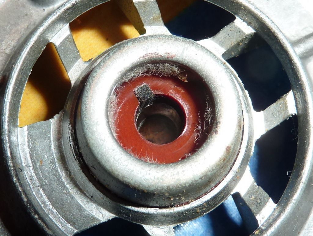
                      The photo below is a bit more of a close up of the 'indoor' end but the flash still tends to flatten everything so it's not as good as actually looking at the real thing. The brown thing is the bit that I think is Tufnol. The bearing itself is behind this.

                      So it sounds like trying to take the 'indoor' caps off may be the way to go… although the taper on the cap and the similar taper on the alloy casting did make me wonder if the whole assembly had been inserted from the 'outdoor' end… but then looking at that end it seemed unlikely.

                      p1060546.jpg

                      #374016
                      IanT
                      Participant
                        @iant

                        No – I don't think a Unimat will do it either Andy!

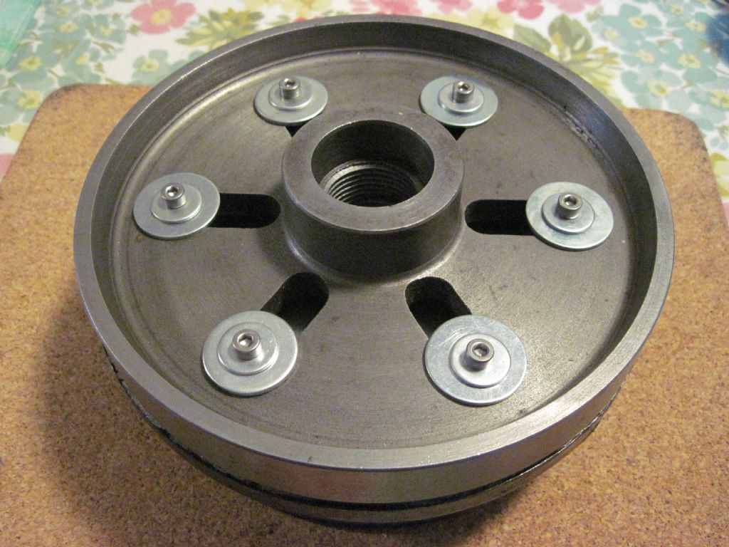
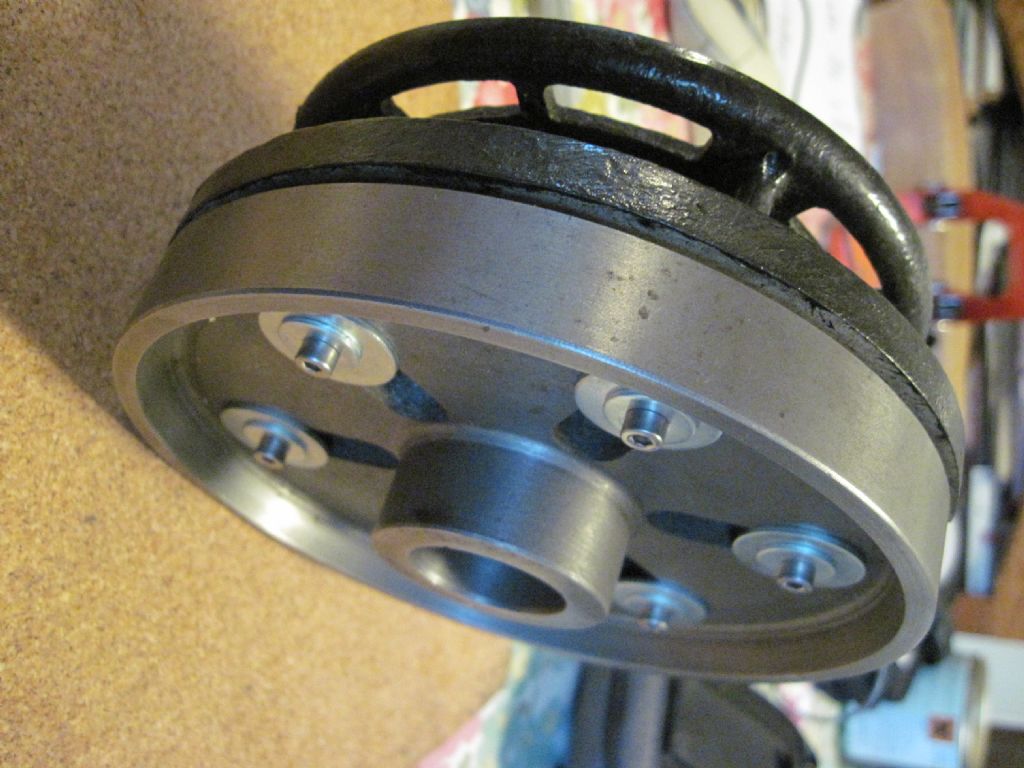
                        I had to mount the end-bell on my Myford faceplate, as none of my chucks would take it. It involved a bit of preparatory drilling and tapping work to match the two together – but it was the only way I could think to do it..

                        So if you have a mate with a bigger lathe – here are some photos of my face-plate set-up.

                        Regards,

                        IanT

                        PS Very useful (and under-rated) things face plates!

                        img_4981.jpg

                        img_4982.jpg

                        img_4983.jpg

                        #374017
                        Andy Carlson
                        Participant
                          @andycarlson18141

                          I've just been having another look at the motor following tonight's discussion.

                          I put it back together to take another look at the bearing wear. Having done this I found that I could not get the rotor to touch the stator in any position so things are probably not quite as bad as I had initially thought.

                          As originally noted, there *IS* bearing wear. There is play in the shaft in the direction of the belt load but not in the direction perpendiclar to this. The motor definitely does make some nasty noises. I now suspect that the noise is caused by vibration of the shaft in the sloppy bearing rather than by the rotor contacting the stator. This noise would, of course, stop when there is enough tension in the belt.

                          #374018
                          Andy Carlson
                          Participant
                            @andycarlson18141

                            Thanks for the photos Ian. I do have a faceplate for the Cowells but clearly I can't be turning bits from the Cowells motor on the Cowells.

                            I now have my thinking cap on to see what could be repurposed to make the 'expanding puller' that Clive suggested.

                            Having measured both 'indoor' and 'outdoor' caps the 'indoor' ones are slightly bigger so clearly they must have been pushed in from the inside end… so pulling them out from that side seems like a logical step. Then hopefully I might get a better clue how the bearing itself is held in because at the moment all except the inside of the bore is hidden by fuzzy felt.

                            Regards, Andy

                            #374021
                            Hopper
                            Participant
                              @hopper

                              The usual way of getting bearings out of motor end caps is to heat the end caps with a heat gun (or good hair dryer) or gently with a propane torch. Once hot enough to make spit sizzle and dance when it hits the metal next to the bearing, the bearings should loosen up enough to be tapped out with suitable punch or even by slamming the cover down on a suitable block of wood. It's best to install the new bearings with similar heating of the end caps. The less force you use on those fragile cast end caps the better.

                              If you can get new plain bearings like the originals they will probably run a bit smoother and quieter than ball bearings but probably not all that noticeably.

                              #374025
                              Andy Carlson
                              Participant
                                @andycarlson18141

                                Thanks. Yes, heat is an option but the dilemma that I have is where to apply any force, be it using a punch, puller or whatever. The construction of the bearing assembly is not easy to decipher from the outside and there are definitely bits like the tufnol piece and the wicking that would be damaged if I do the wrong thing.

                                At the moment it seems like the inner cap needs to come off first. A puller seems like the best option for this, especially on the non-pulley end where the outer cap is completely blank.

                                #374033
                                Hopper
                                Participant
                                  @hopper

                                  I had assumed the whole thing was a kind of cartridge encased in an outer pressed metal shell turned over at the ends. But hard to tell from the pics.

                                  You should be able to heat the end cap up to a bit over 100C or so without damaging the tufnol or wicking. But really, you don't want to be re-using old worn out tufnol seals or worn out felt wicking so maybe not worry too much about them? A bit of heat and you might be able to ease that end cap (if it is an end cap and not a cartridge) out with a standard seal puller.

                                  You might take a measurement and see if you could replace the whole lot with a standard sized sintered bronze oilite type bushing and two standard neoprene lip seals.

                                  #374035
                                  IanT
                                  Participant
                                    @iant

                                    Hard to tell Andy but I don't think you have an Oilite bearing in there. it looks like a felt oil reservoir very similar to the one on mine. If you can remove the tufnol cover – you may find an inner die-cast ring that holds a thin bearing (I called mine a 'shell' bearing – but it was very similar to a Glacier). Whereas I've pulled Oilite bearings out quite easily in other situations – I couldn't shift this one (although I didn't try heating it). So I just cut-out the whole thing.

                                    However, even if I could have changed just the bearing itself – the shaft was badly scored – so a new bearing would not have lasted too long. My spindle had a stepped shaft – so I was able to turn the damaged part away – but your shaft seems to be a single diameter, which means you would have to reduce the whole length – possibly weakening it (and then your pulley wouldn't fit either).

                                    However, if your shaft doesn't seem badly worn or damaged – then maybe the bearing isn't too bad either. If you think the bell ends may have been swopped in the past – then the rear cover should come off fairly easily (wooden dowel tapped from the inside). Then you could try both bell ends on the pulley side of the shaft and see how well they fit – can you 'rock' them slightly? If you 'mic' along the shaft is there discernible wear on it – checking along the length from the pulley end?

                                    Your original concern was that the rotor was hitting the coils but if this is not the case – then it might be best to leave well alone or decide to bite the bullet and find a new small fractional motor. I don't know how the Cowells motor is mounted – but a new mounting for a replacement motor might be an easier task for you – and these small (cap start?) motors are not too expensive if you can mount them. In my case I needed an Imperial B56 flange type mounting and whilst replacement B56 motors are still available – they are about twice the price of the same sized metric one (which wouldn't fit the machine easily). So I decided a repair was required – but in your case there might be other easier/affordable options…

                                    Regards,

                                    IanT

                                    #374036
                                    Hopper
                                    Participant
                                      @hopper

                                      PS, have a look around on this Permawick (thanks Michael G) website at their cartridge type bearings. It may that the whole "blister" domed housing you are looking at in the inside end cover is part of the cartridge. So you would heat up the end cover and let the whole cartridge drop out of the hole. See photo of cartridges here **LINK**

                                      The cartridge contains the bearing, the oiled felt and the seals at each end, all in a drop-in, drop-out unit. Commonly used on el cheapo air conditioning condenser fan motors etc. Low cost but they run for years.

                                      Depending on how readily available a replacement cartridge is, the ball bearing conversion might be looking better all the time.


                                      Edited By Hopper on 01/10/2018 09:15:12

                                      #374054
                                      John Hinkley
                                      Participant
                                        @johnhinkley26699

                                        By the look of the photos of the end bells, they seem to be roughly symmetrical and from your latter posts, I get the impression that you may be shying away from doing anything? If the wear is mainly in one direction, have you considered the possibility of their reassambly 180° from their original orientation. That would present the relatively unworn area of bearing to the direction of pull from the belting, no? Alternatively, reassemble "correctly" and turn the whole motor 180°. I'm not familiar with the Cowells lathe, so forgive me if my suggestions are somewhat wide of the mark. They are just the lateral thoughts of a trainee idiot.

                                        John

                                        #374087
                                        V8Eng
                                        Participant
                                          @v8eng

                                          Maybe a daft question because I do not know where you are based, have you looked in the phone book to see if there is an electric motor rewinder/repairer in your area?

                                          They might be prepared to give a quick bit of advice if you took the motor round.

                                          #374119
                                          Andy Carlson
                                          Participant
                                            @andycarlson18141

                                            I had initially thought that the previous owner must have rotated the ends through 180 degrees but this theory was an attempt to explain why the noises stop when the belt is tight. Now I think that the noise is down to vibration of the shaft in the bearing. This theory explains why the noise goes away with no need to assume any other changes… and it also means that rotating the ends wont help with the noise.

                                            I'm not shying away but having taken the thing apart and discussed it here I do now think that the problem is less severe than I had first thought. 'Leave well alone' is definitely still an option in the short term but I plan to keep this lathe and don't really want to put up with the noises indefinitely. Replacing the whole motor is an option but not my first preference.

                                            At the moment cautious, reversible steps towards replacing the plain bearings 'like for like' (or very close to) is my preferred option.

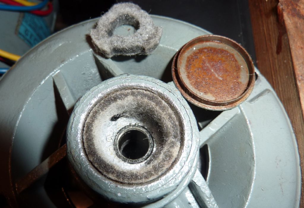
                                            Some progress to report… I found that the outer end cap on the non-pulley end came off with some very light taps with an 8mm rod through the bearing. Taking out a wick 'washer' revealed the view in the photo below.

                                            So this does seem to be a thin walled bush. As far as I could measure by poking around with the calipers it seems to be roughly 10.8mm OD (and an 8mm shaft). The bush is inside a bore in the main casting but this part of the casting is surrounded by several slots for more wick material.

                                            I've also had an unsuccessful attempt to get the inner cap off using a few quick and dirty options. My anchor bolt does not expand enough to grip the cap so I'm planning to make something with a step to engage positively inside the rim. Not sure if that will happen today because I have some errands to run.

                                            Thanks again for your suggestions so far.

                                            Regards, Andy

                                            p1060549.jpg

                                            #374121
                                            Andy Carlson
                                            Participant
                                              @andycarlson18141

                                              Oh, and I have looked for local motor rewinds people. I'm sure there used to be one or two but now I can only find companies that seem to trick the search engine to make them appear to be local but turn out to be a long way away on further investigation. I also checked the yellow pages today but this is a very flimsy affair nowadays and didn't turn up anything useful.

                                              #374123
                                              Emgee
                                              Participant
                                                @emgee

                                                Hi Andy

                                                By the looks of the recent picture there is room for a ballbearing adaption as IanT, probably more work and perhaps beyond the size you can turn but a worthwhile repair.

                                                IMO ZZ seals are better than the rubber seals as they tend to create heat by continuous contact on the bearing inner and outer parts.

                                                Emgee

                                                #374124
                                                Andy Carlson
                                                Participant
                                                  @andycarlson18141

                                                  I still dont want to do that but you did get me thinking,,, that the recess in the photo is kinda ball race shape and sized.

                                                  The diameter of the recess varies between 22 and 21.4mm and it is about 10.5mm deep. A quick search for a sample 8mm ball race seems to be 22mm OD and 7mm wide so it would go in there with a minimal amount of machining.

                                                  I think it might just about swing in the gap of the Cowells bed if mounted on the face plate… but only if I can get the inner cap off because that stands maybe 5 or 6mm proud of the casting.

                                                  I also reckon I could temporarily drive the Cowells by holding its motor pulley in the chuck of the Unimat. Never tried it but I think it would have enough grunt for a small amount of alloy machining at 22mm diameter..

                                                  How concentric the existing recess is and how I would find a reference for clocking the motor end when mounted on the faceplate remain unresolved. Clocking inside an unevenly worn bearing doesn't seem like the right answer. Maybe inside the step where it mounts to the main motor 'tube' is the least bad option.

                                                  But whatever happens… getting the inner end caps off needs to be the next step.

                                                  #374127
                                                  Jeff Dayman
                                                  Participant
                                                    @jeffdayman43397

                                                    Clocking the locating diameter of the end bell that engages the motor housing tube would probably give a good result. Unless your motor was manufactured different to the majority of all small motors made. Generally the end bells are machined for bearing bore and locating diameter to housing in the same setup. (or were several places I worked, who made motors)

                                                    #374145
                                                    Andy Carlson
                                                    Participant
                                                      @andycarlson18141

                                                      Thanks. I was looking at SKF 608-2Z.

                                                      The web site quotes the nominal dimensions and then has a popup table which attempts to convey information about tolerances. I can't make head nor tail of it but I would like to know the upper and lower limit of the bore size so that I can figure out if it will slide onto the shaft… or need gentle or extreme persuasion.

                                                      http://www.skf.com/my/products/bearings-units-housings/ball-bearings/deep-groove-ball-bearings/deep-groove-ball-bearings/index.html?designation=608-2Z

                                                      Regards, Andy

                                                    Viewing 25 posts - 1 through 25 (of 51 total)
                                                    • Please log in to reply to this topic. Registering is free and easy using the links on the menu at the top of this page.

                                                    Advert

                                                    Latest Replies

                                                    Home Forums Manual machine tools Topics

                                                    Viewing 25 topics - 1 through 25 (of 25 total)
                                                    Viewing 25 topics - 1 through 25 (of 25 total)

                                                    View full reply list.

                                                    Advert

                                                    Newsletter Sign-up