Frustrated

Frustrated

Home Forums Beginners questions Frustrated

Viewing 22 posts - 1 through 22 (of 22 total)
  • Author
    Posts
  • #173990
    pgk pgk
    Participant
      @pgkpgk17461

      So having battled the thing into the shed, cleaned it, got it on the stands on high tensile bolts for adjustment, levelled it patiently within the scope of quality ordinary levels – it won't run.

      Now either Im doign soemthign stupid – which is entirely possible – or I have a fault that isn't easy to trace.

      This is a chester crusader delux with all the add-ons. I did wire in the coolant pump last night and when I couldnt get the chuck to run I switched that on just to see… whereupon the shed consumer unit prompty tripped.

      For the moment I've disconnected that and checked that my wiring was to the right colour codes and sheathed the ends in insulating tape.

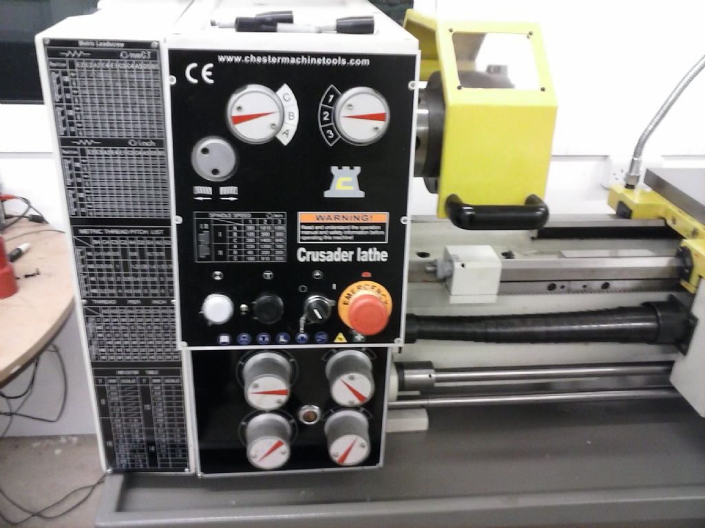
      As I see it the lathe has a safety cutout on the end belt guard. A cutout on the chuck guard. And a cutout built into the emergency switch. So assuming I have it right the order of operation is check the guards are in use, Power on at mains.. when a white power light on the panel comes on. rotate the emergency switch so it pops out and then the thing should run assuming speed and gear selections are meshed when the red handled lever goes from neutral to forward or reverse spindle? There's also a jogging button that doesn't work.

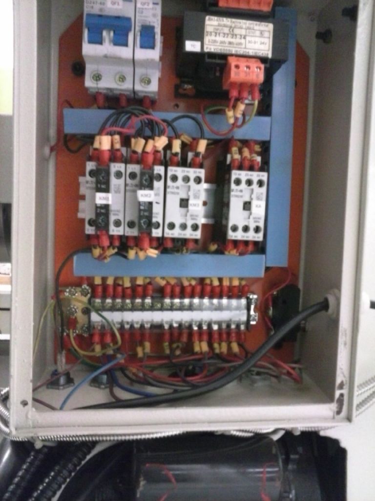
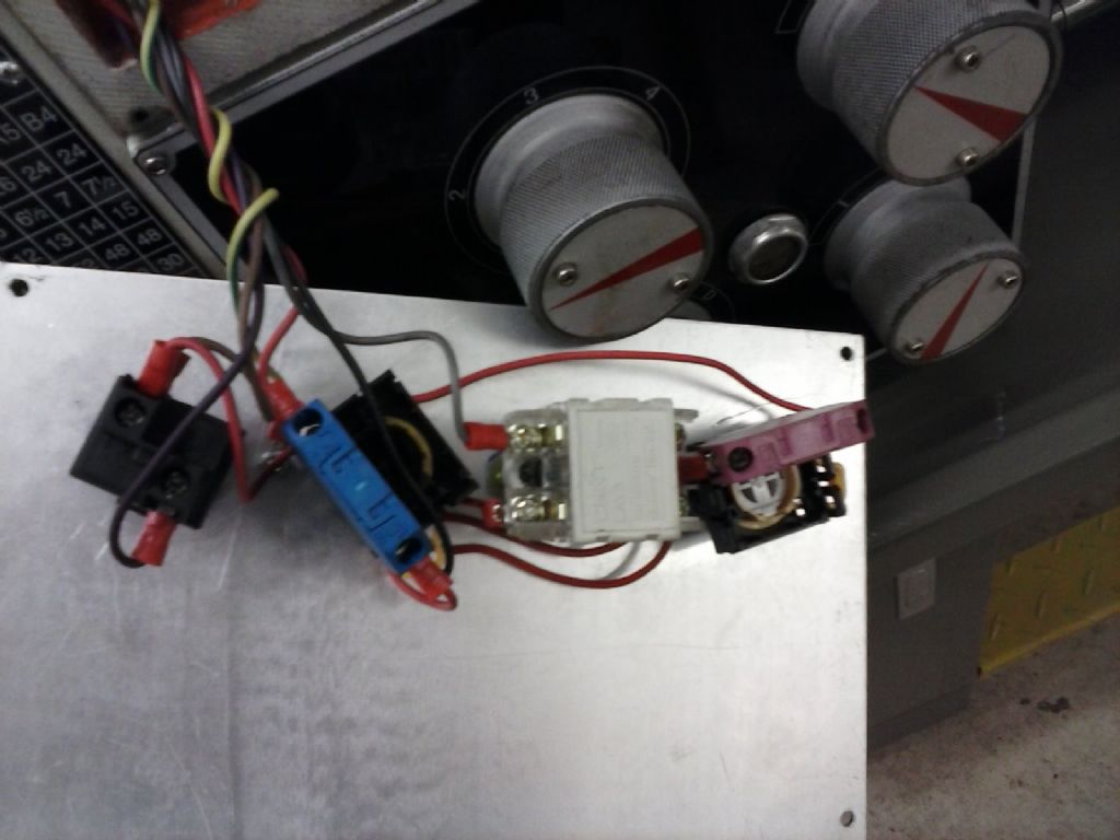
      I have pulled the panel off the electrical board at the back.. and then stared in dismay at the neat mass or wires in there. there are two trip switches..one double and one single neither of which had tripped. With the thing under power I've run a simple tester that picks up voltage in wires (the sort of thing used for checking walls) and there is no pwer going to motor or through either end guard switch or chuck guard switch. I'm loath to pull all the levers and uttons off the front to access the ack of those switches without having called chester first – and of course they're closed over xmas.

      Hopefully (long shot) I'm missing something obvious??. I do get power to the lamp and DRO and obviously that coolant pump.

      my best guess since neither main lever nor jog work is that it's the emergency switch or it's wiring. Does that make sense?

      #7420
      pgk pgk
      Participant
        @pgkpgk17461

        Crusader not working

        #173996
        Gray62
        Participant
          @gray62

          Hi,

          Not sure if it is similar, but in My Warco GH lathe there are 2 fuses off the 24v transformer, one for the lamp and the other feeds the control/interlock circuit. Check that the fuse is ok.

          If you take an insulated probe you should be able to push in the contactors for fwd rev to prove you can get power to the motor,.

          Check for 24v at the jog switch, if this is not present you have a control circuit problem.

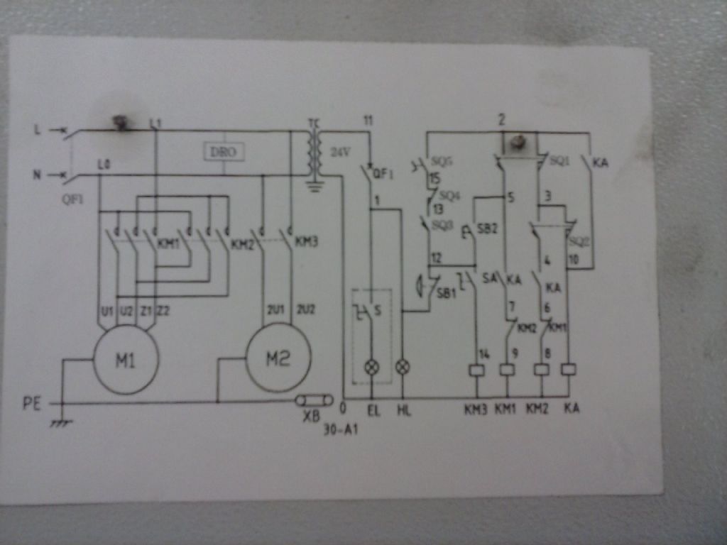
          post a pic of the control panel and if it's there the wiring diagram off the inside of the control box, will help advising further.

          regards

          Graeme

          #173998
          Hamish McNab
          Participant
            @hamishmcnab62554

            Basic question, is it single phase or three phase? Unless you know what you are doing volt stick type testers are not a good idea and a tester that has probes to make actual contact should be used. If you are not confident about doing live testing an electrician would be your next port of call.

            #174002
            Bazyle
            Participant
              @bazyle

              After closing the covers guards etc did you check tha the interlock switches actually closed. I've seen one instance where the changegear cover switch was a sort of cam affair that needed a tweak.

              Do you have a circuit diagram? If you can find the equiavlent machine on Grizzly their wiring diagram will be in colour.

              I think a normal electrician will be out of their depth with control circuits. An old fashioned car electrics bod or radio ham is a better bet.

              #174006
              Bazyle
              Participant
                @bazyle

                Page 82 starts the wiring it's the G0750 but with a few trivial changes like puting the switches left to right instead of right to left.

                #174015
                matt
                Participant
                  @matt27093

                  Does sound like problem with interlock circuit. If your using detector for picking up voltage in cables in walls, I'm pretty certain that would only detect AC. Interlock circuit should be 24vdc. You won't detect any voltage in motor wiring until motors actually turning.

                  Usually you can hear a click as each interlock switch physically closes. Try moving closing each of interlocked guards In turn and listening for noise as switch closes. If one doesn't make any noise it might not be moving switch enough to trigger it.

                  #174019
                  pgk pgk
                  Participant
                    @pgkpgk17461

                    I'll try and answer all the questions – with thanks for taking an interest folks:

                    Single phase 230v. I had looked at the grizzle pics before.. only a passing resemblance to mine.

                    The switch access to the forward/reverse lever on the grizzle site seems to be a simple cover at the end of the bar..not so here. I'm loath to undo that area here.

                    The brake cutoutswitch seems to be working (as in clicks) and did have a chinese fag butt stuck in it when the lathe arrived.

                    I don't have a functional voltage tester apart from my mains voltage detector thingy. And, no it can't pick up on the 24v to the on light which I guess is DC anyway. About the only way would be to find a 24v lorry bulb or cobble up a bunch of 2v led's in series with a resistor (if I can find where I put those last).

                    I have taken pics but my phone demands software to link to the PC to upload and with the bog-slow connection here in the sticks it says another hour+ to download to hobbyshed pc

                    All the interlocks/switches do click when fiddled with.

                    #174020
                    Hamish McNab
                    Participant
                      @hamishmcnab62554

                      My initial question was based on a quick look at the manufacturers web page which gives the option of single single or three phase. The circuit diagram is for a single phase lathe which I assume yours is? As a "normal electrician" the manual shows a transformer providing 110volts ac for the control circuits/contactor coils and 24volts ac for the lamp, so not quite sure where DC comes from.

                      If the machine was working before you got it then I would agree that it may well be an interlockswitch, none of which are shown on the circuit diagram????

                      An industrial type electrician would be able to sort it out as it does not look technically difficult.

                      Good luck.

                      #174021
                      JasonB
                      Moderator
                        @jasonb

                        You need to check if they click when the cover etc is opened/closed not just when fiddled with

                        #174023
                        John Stevenson 1
                        Participant
                          @johnstevenson1

                          Done a few of these faults for various customers.

                          What happens is the 3 or 4 safety switches daisy chain around the machine. Usually on this type of machine with the panel on the back the chuck guard is usually first, then it goes to change wheel switch, e-stop and then brake switch.

                          Not always in that order but you can usually spot where the circuit starts and where it comes back in. If those two terminals are bridged it takes the whole safety circuit out of the equation.

                          I am not saying bypass this to run this way but if it's taken out and it then runs you know where the problems lies and it's even possible to isolate each switch in turn to find the culprit.

                          Whatever happens on machine wiring it is a logical process. No good just diving in and then diving somewhere else.

                          #174027
                          pgk pgk
                          Participant
                            @pgkpgk17461

                            Sorry, I shou;d have said clicked and clicked closed on activating guards and covers.

                            Agree no point diving in without understanding it..and that's where I'm struggling. And yes, it was a pure assumption that the 24v would be DC.

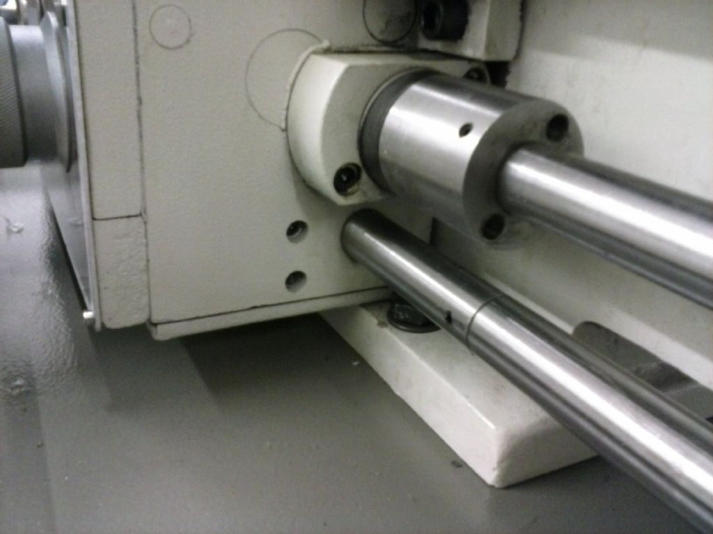
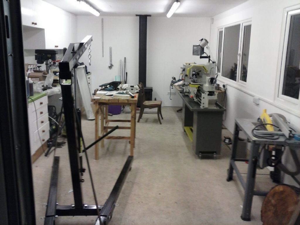
                            I remembered I have the software on this other PC and figured out how to upload pics…

                            #174031
                            matt
                            Participant
                              @matt27093

                              Ok your control circuit is 24v AC. Wall type tester probably wouldn't pick up that low an AC voltage, which you've confirmed by trying it on the wires to the power lamp when it's on. I'm guessing the interlock switches are the ones label SQ1-5 on the diagram. Are there any labels on the actual interlock switches?.

                              #174034
                              Hamish McNab
                              Participant
                                @hamishmcnab62554

                                NICE workshop. Well the circuit diagram is more like the real thing and quite straight forward with the control circuits on 24v ac. Having gone back to your original post a bit concerned that you popped the circuit breaker in the first instance. It looks like there are 5 safety switches which are SQ1>5 on the diagram and all need to be closed in order that relay KA closes and allows the contactors KM1 or KM2 for forward or reverse. KM3 looks like the pump contactor. Have you tried it again without the pump being connected?

                                #174035
                                Chris Denton
                                Participant
                                  @chrisdenton53037

                                  Is this a machine that you bought new?

                                  If so then best to let the retailer sort it out. It's not worth causing further damage or risking them not wanting to help.

                                  As someone said above, an electrician probably wouldn't / couldn't do it, so for someone not an electrician to do work on it would be crazy. If you can't work out which the safety circuit is then again – you shouldn't be working on it.

                                  Out of interest, was it an RCD (or RCCB) or MCB that was tripping?

                                  #174040
                                  pgk pgk
                                  Participant
                                    @pgkpgk17461

                                    None of the accessible interlock switches (brake, gear cover, emergency stop) have any SQ-type labels.

                                    I disconnected the power wires to the pump and wrapped in insulation this am and operating the pump switch now does nothing (or trip anything).

                                    Yes it is brand new..just installed so the thought of taking it all down for a return to shop is pretty daunting. Chester should be back at work 2nd Jan and obviouslyy i'll call them. I would be quite happy to drive back and be shown in person how to bypass each item….

                                    It was the main RCD for the shed units that tripped, not just the one 13amp circuit but not the internal trips on the lathe.

                                    Without a way of measuring across the interlocks I'm stuck – even if I thought I knew what i was doing.

                                    If it comes to it local sparks may well be a person to call..he does commercial and farm machinery stuff as well as domestic and solar panels etc. Only real problem with most local trades is actually getting the beggars to turn up unless you have a hand on their collars.He's 2 mths late for the last job he was supposed to do for me!

                                    #174041
                                    Hamish McNab
                                    Participant
                                      @hamishmcnab62554

                                      If it is brand new, then back to the suppliers and leave well alone meantime.

                                      #174047
                                      Bazyle
                                      Participant
                                        @bazyle

                                        The online version of the manual has a different circuit diagram……………

                                        The main circuit breaker trip is quite possibly just it not liking the inductive load which is not an uncommon problem. You might anyway try wiring the coolant pump to a normal plug to try it out. And make sure your lights are on a seperate circuit.

                                        #174052
                                        pgk pgk
                                        Participant
                                          @pgkpgk17461

                                          The lights are on a seperate circuit..in fact my shed has two seperate 13A circuits and 2 lighting circuits( we went OTT) and it was the main breaker to the panel that tripped. I doubt that'd be inductive load to the coolant pump. it's either a pump fault or looking at the thing I wonder if there's eough clearance between the contact bolts and the metal cover.. which might benefit from an insulated lining.

                                          It's tme to stop messing and just ring them on the 2nd <sigh>

                                          #174088
                                          mechman48
                                          Participant
                                            @mechman48

                                            Considering its a new machine I would check your warranty, as some companies state that any attempt to 'fiddle' with equipment will void any warranty coverage. It should have been 'fit for purpose' straight out of the box.. set it up plug it in & away you go .. shouldn't have to mess on with major wiring probs.. any probs should be resolved by Chester's in the first place, either offer you an exchange or send a electrician to home fix it.. depending on warranty terms.. considering you have already set it up I doubt if the 'exchange' scenario will take place so the other option should be available… anyhow these machines should be checked prior to delivery.. as they claim angry ? I would be on the phone to Chester's sharpish Mon a.m. plus, bear in mind if anything happens to you or your workshop / house due to incorrect wiring, incorrectly fitted by a 'Non qualified', electrician then all they'll do is say… What! bye bye sunshine  Accident, home /contents insurance claim disallowed due to ….  thinking .

                                            George.

                                            Edited By mechman48 on 31/12/2014 11:53:59

                                            #174091
                                            pgk pgk
                                            Participant
                                              @pgkpgk17461

                                              Success!

                                              Well some anyway. I do worry at problems and it occurred to em that fiddling with the thing under power when i didn;t know what i was doing was unnecessary. A simple battery and buzzer checked the front panel swtches and the main cover interlocks. then i realised that John Bogstandard had it right first time. I'd failed to appreciate which way the brake switch really worked and that explains the original finding of a chinese fag-butt in there (to close it so it ran). A bit of a bend to the brake lever mesh with that switch and it operates as it should.

                                              So I now have a spindle that goes around. Getting the gearbox and feedscrew to work was another fiddle… hopefully just 'cos its new but I had to manually rotate the gear cogs to get the levers to mesh and feedscrew to finally run.

                                              Now for some more pratting and learning curve to get the leadscrew and halfnut indicating…. And I still have to solve the coolant pump.

                                              I'll run it for a goodly time through the speeds and see if it loosens up or it'll still be a phonecall.

                                              But I'm a happier bunny

                                              #174113
                                              pgk pgk
                                              Participant
                                                @pgkpgk17461

                                                John, you'll have to bear with a newbie… by drop in dial do you mean the thread dial?

                                                The learning curve will go on. I've run it through all the speeds and gears.. and I'm seeing a colour change to the oil in the sight glasses.. so that'll get changed when it's had a decent run

                                                I've figured out the leadscrew and feedscrew but the leadscrew reverse lever seems to engage a gear but the leadscrew (threading) doesn't run backwards. Any clue? Something I'm not doing?

                                                The other thing i can't find is how to zero the feed dials. Not particularly an issue with the DRO unless it dies.

                                                TIA

                                                pgk

                                              Viewing 22 posts - 1 through 22 (of 22 total)
                                              • Please log in to reply to this topic. Registering is free and easy using the links on the menu at the top of this page.

                                              Latest Replies

                                              Home Forums Beginners questions Topics

                                              Viewing 25 topics - 1 through 25 (of 25 total)
                                              Viewing 25 topics - 1 through 25 (of 25 total)

                                              View full reply list.