Draughting Pens

Advert

Draughting Pens

Home Forums Workshop Tools and Tooling Draughting Pens

Viewing 25 posts - 51 through 75 (of 81 total)
  • Author
    Posts
  • #239966
    DrDave
    Participant
      @drdave
      Posted by Neil Wyatt on 23/05/2016 21:44:21:

      My dad used to cover his RC models with light fabric.

      I seem to recall about hearing well-washed draughting linen being used.

      I used to do the rounds of the local haberdasheries, looking for the most psychedelic nylon cloth that I could find to cover my control line combat models… It used to take longer to dope shrink the cloth than to reduce the aeroplane to "pieces of eighth" in the inevitable mid-air.

      To get (almost) back on topic, my mum used to trace when she was a girl. One of the problems she recalls was sweating on hot days: any moisture on the linen & that tracing was scrap.

      Advert
      #239971
      Georgineer
      Participant
        @georgineer

        Neil – It is indeed the horn of a mine, though I know nothing more about it than that.

        DrDave – There must be some mistake. I was given to understand that horses sweat, men perspire, and ladies glow.

        George

        #239972
        Simon Williams 3
        Participant
          @simonwilliams3

          My Mother, having brought up five of us, re-discovered her creative roots and took up Batik printing. In her case she was interested in drawing pictures of birds, animals, landscapes in Batik.

          She discovered that the beautiful quality linen resulting from washing draughting cloth made a superb material to carry the wax resist, and took the dye reliably and with an excellent resolution so she could get the detail she wanted.

          IIRC she washed quite a lot of this linen, having been given a roll of it by an interested neighbour who no longer had a use for it. Washing out the conditioner (gelatin?) was easy enough, but she found that the only easily available solvent for removing the wax resist after each stage of the dying procedure was petrol. Needless to say Father, who smoked heavily, was not allowed in the kitchen on those days!

          I still have my Father's collection of Graphos pens, if they are of interest to anyone as historic memorabilia please PM me and we can discuss further.

          Regards to all

          Simon

          #240006
          SillyOldDuffer
          Moderator
            @sillyoldduffer
            Posted by Neil Wyatt on 23/05/2016 19:08:44:

            Posted by Georgineer on 23/05/2016 14:49:34:

            Here's an exercise drawn in ink on linen by my mother as an 18 year old tracer in HMS Vernon (Portsmouth) in 1936. I still have the pen and compasses she used.

            What a fantastic keepsake!

            Is it a trigger horn off of a sea mine?

            Googled this a bit – mines used chemical triggers, so is it a torpedo fuse?

            Neil

            Edited By Neil Wyatt on 23/05/2016 19:15:38

            This drawing reminded me of something I read somewhere, and the strange workings of my memory finally retrieved it this morning as being from Norman Friedman's "Naval Weapons of World War One".

            It's a Hydrostatic Switch from a mine, not a horn. It's main purpose is to activate the mine after it's been laid.

            This type of mine is anchored to the seabed by a kind of winch and cable arrangement that sets the operating depth. This could be as deep as 100m to catch submarines, but more usually would be just too deep to be set off by passing fishing boats. Mines do not float on the surface.

            In storage the top of the switch is sealed with a soluble pad. The mine is safe until this pad has been slowly dissolved by seawater, by which time the mine layer should be well away. The outer top cap is pulled off just before the mine is dropped into the sea.

            Once the pad has dissolved seawater can enter the innards of the switch to press on the diaphragm. At operating depth the piston is pushed sufficient against the spring to make an electrical connection between the two lower bolts. This brings a battery into the firing circuit and activates the mine. After that bumping a horn will set it off.

            A secondary purpose of the switch is to make the mine less dangerous should it accidentally come adrift. Randomly drifting mines are dangerous to everyone. If the cable breaks the mine floats to the surface. With luck removing pressure from the piston will disconnect the battery, making the mine "safe". I say "with luck" because after several months in the water corrosion or sea-life might have jambed the mechanism.

            Friedman reproduces a drawing on Page 361 of a complete British EC II mine that includes one of these devices. On the drawing it's labelled "Hyd Switch Mark III" .

            The drawing in the book isn't as good as that traced by Georgineer's mum. Well done her!

            Cheers

            Dave

            #240022
            Muzzer
            Participant
              @muzzer
              Posted by JasonB on 23/05/2016 20:58:40:

              That's an unusual engine Andrew, would be a good subject for a modelsmiley

              Looks like the very thick piston rod runs through a guide at the top and the collar on teh rod drives the crank but I can't see what provision there is for the sideways movement of the pin as it rotates?

              J

              Andrew – you must have pondered the design for many hours over the years! I'm assuming that the connection between the pin and the disk on the piston rod must be either spherical or at least capable of accommodating 2 axes of rotation. Was it his own design? Do you know if it was ever built? Perhaps somebody ought to have a go at a making a detail design and then building it….

              Interesting that the "plan" view is actually a sort of perspective / slightly isometric view. And the views show shadows. Somewhere between a technical drawing and a rendered view!

              Murray

              #240023
              JasonB
              Moderator
                @jasonb

                I think Neil may have it right when he says its a "Twisty" one, there is no sign of valve gear and the "crank" could be harlf a bevel gear with the other half driven by the shaft comming out the top of the cylinder which point to a turbine of some sort.

                I don't think the plan is iso or perspective but it does show draft angle on the main castings.

                Indeed it would make an interesting project, maybe andrew could provide a few close ups and also share the other two engines

                #240024
                Neil Wyatt
                Moderator
                  @neilwyatt
                  Posted by SillyOldDuffer on 24/05/2016 09:55:11:

                  It's a Hydrostatic Switch from a mine, not a horn. It's main purpose is to activate the mine after it's been laid.

                  Dave

                  Thanks Dave, I assumed what must be the soluble pad was a rubber buffer.

                  Pleased that I figured out the basic operation though!

                  Neil

                  #240034
                  SillyOldDuffer
                  Moderator
                    @sillyoldduffer
                    Posted by Neil Wyatt on 24/05/2016 12:06:47:

                    Posted by SillyOldDuffer on 24/05/2016 09:55:11:

                    It's a Hydrostatic Switch from a mine, not a horn. It's main purpose is to activate the mine after it's been laid.

                    Dave

                    Thanks Dave, I assumed what must be the soluble pad was a rubber buffer.

                    Pleased that I figured out the basic operation though!

                    Neil

                    I'm a sucker for buying old technical books and trying to work out exactly what some of the drawings mean. Sometimes it's like doing a cryptic crossword!

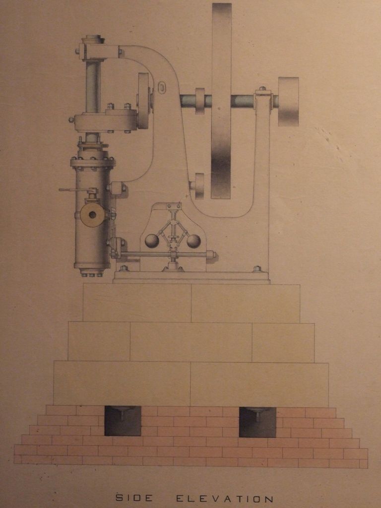
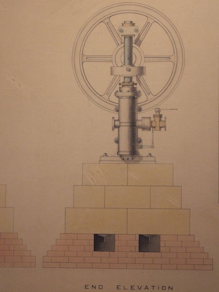
                    I'm having a bit of fun in this thread decoding Andrew Johnston's Vertical Steam Engine. It looks as if a pin driven by the piston runs without lubrication in a circular groove: surely that would have caused trouble! It also seems that the valve gear is meant to be driven by a belt, which is peculiar too. (Not that I know anything about the subject!)

                    I guess the drawing is intended to give a general idea of the Engine's layout and some of the detail is missing.

                    Another mystery is what the designer thought the advantage of such a configuration would be? I wonder if it was ever built and what it was used for? If the brickwork is to scale it would be about 6 foot high. (The plan says it's scaled 1 1/2" to the foot but we don't know how big the paper is.)

                    The quality of the drawing and colouring is excellent: it must of taken a lot of practice to get that proficient. No TV or Internet back then.

                    Dave

                    #240035
                    JasonB
                    Moderator
                      @jasonb

                      I thought that the pully and belt would drive a shaft to bevel gears just above the governor as I can't see any other way it is driven

                      #240036
                      Muzzer
                      Participant
                        @muzzer
                        Posted by JasonB on 24/05/2016 12:00:38:

                        I don't think the plan is iso or perspective but it does show draft angle on the main castings.

                        I agree on closer inspection. It's actually just shadow – but it's cast on the machinery but not the foreground which is confusing.

                        If you were to build it, you'd certainly need to decide if it's a reciprocating engine (my vote) or a turbine. Of course, it may have been a "naive" design that would never work. No disrespect intended but we have no idea how real it was. Hopefully Andrew knows something about it….

                        #240037
                        SillyOldDuffer
                        Moderator
                          @sillyoldduffer
                          Posted by JasonB on 24/05/2016 13:22:05:

                          I thought that the pully and belt would drive a shaft to bevel gears just above the governor as I can't see any other way it is driven

                          Ah ha! That makes sense, no problem driving a governor with a belt.

                          Even though I can't see any valve gear I think it reciprocates too.

                          #240060
                          Neil Wyatt
                          Moderator
                            @neilwyatt

                            For anyone not familiar with the 'twisty' concept , its a single or double acting engine that has an extended piston with ports in its sides, the drive to the flywheel is some sort of universal joint so as it lifts and lowers the piston it also covers and uncovers the ports.

                            With care its possible to make an engine with only two moving parts (piston and flywheel/shaft). The downside is the lack of adjustment.

                            Twisty was an example described in ME as a new idea, but in fact a similar model had been descrivbed many years before, and clearly this engine is even older.

                            Nihil sub sole novum

                            Neil

                            #240065
                            JasonB
                            Moderator
                              @jasonb

                              Just had a look at that Twisty in ME and you could well be right, just ned to work out why it has such a thick piston rod or is that a tube full of steam

                              #240078
                              John Fielding
                              Participant
                                @johnfielding34086

                                I think the engine is definitely a reciprocating type.

                                I assume the crank pin engages with the lump attached to the piston rod and it slides in the upper tail rod support. There is probably an oil well in the lozenge shaped bit which is bolted to the piston rod, you can see the cross bolt in the diagram. That would be enough to keep the crank pin and piston rod lubricated.

                                The governor is driven by the belt pulleys (belt not shown in diagram) and there must be a pair of bevel gears inside the casting. The governor operates the steam regulator. The mystery is – where is the valve gear? Possibly it is contained within the piston casting and as with most stationary engines it only rotates in one direction, so a simple piston or slide valve would do the necessary.

                                I have seen similar steam engines in old books but never one like this one.

                                There appears to be a sort of name or logo cast into the main support but it is too indistinct to decipher.

                                #240135
                                Anonymous
                                  Posted by Muzzer on 24/05/2016 11:53:49:

                                  Andrew – you must have pondered the design for many hours over the years! I'm assuming that the connection between the pin and the disk on the piston rod must be either spherical or at least capable of accommodating 2 axes of rotation. Was it his own design? Do you know if it was ever built? Perhaps somebody ought to have a go at a making a detail design and then building it….

                                  Indeed I have pondered it over the years. I can sort of see how the crank may be articulated, although it seems rather complicated. Neil may well be right about it being a twisty. It seems to show steam entering on one side with the exhaust in line on the other. I'm afraid I have no clue about the origins of the engine, or whether it ever existed in full size. Here are some closer shots of the elevations:

                                  side elevation.jpg

                                  end elevation.jpg

                                  plan.jpg

                                  Andrew

                                  Edited By Andrew Johnston on 24/05/2016 22:54:50

                                  #240138
                                  Anonymous

                                    Some background – my grandfather was born in 1888 and came south from Edinburgh in 1904 looking for work. So he would have been about 20 when the drawing was done. That seems a little late for an apprentice piece? My mum thought it might have been a demonstration drawing (like an artists portfolio) when looking for work. If that is the case it may well be that the engine never existed, and wouldn't work as drawn. However, that seems odd. Remember that in the good old, bad old, days the draughtmen often did a lot of the detail design and calculations, so not good if the engine design was wrong?

                                    I know that my grandfather was working at the Royal Aircraft Factory at Farnborough in 1912, as there is an entry in Geoffrey de Havillands flying logbook in that year stating "took Mr Johnston for a ride". In the early 1920s he was working on high voltage switch gear at BTH in London. In 1925, a few months after my father was born, he moved to Yeovil to join Westlands as chief draughtman. As an aside my father had his first trip in an aeroplane at Westlands. Aged 10 he cycled out to the airfield, spoke to the test pilot, Harald Penrose, and was given a trip in the back of an aeroplane about to be test flown. Can't imagine that happening today!

                                    In the late 1930s my grandfather moved to Airspeed as chief draughtsman, working with Tiltman and Neville Shute Norway. He lived in Portsmouth during the war, where they had an indoor Morrison shelter, rather than the more common Anderson shelter. When Airspeed was taken over by de Havilland my grandfather transfered across and became their design office manager at Christchurch. He retired from de Havilland in 1960, and promptly joined a local engineering company in charge of the stores.

                                    Andrew

                                    #240150
                                    JasonB
                                    Moderator
                                      @jasonb

                                      Andrew, thanks for the extra photos and family history.

                                      J

                                      PS could you provide one dimension so an idea of size could be worked out, say flywheel diameter

                                      Edited By JasonB on 25/05/2016 07:27:45

                                      #240152
                                      John McNamara
                                      Participant
                                        @johnmcnamara74883

                                        Gee Andrew

                                        Those drawings are wonderful. He must have used CAD LOL

                                        I hope they are framed and hanging on the wall (Not near Sun). Too good to be locked away.

                                        Regards
                                        John

                                        #240153
                                        Muzzer
                                        Participant
                                          @muzzer

                                          Andrew – that's quite a respectable aviation engineering family history. There definitely seems to be a genetic component to what makes us tick. In my case, it seems to be agricultural engineers and carpenters, also from the Scottish Borders – not quite in the same league perhaps! My dad came South for work with his PhD and found ICI (remember them), while his cousin (and now his son, my second cousin?) took the other route and stayed to run the farms.

                                          From what I can now surmise, it's pretty much complete as shown. The "Twisty" concept sounds right, whereby the piston is also a rotary valve, being both raised and lowered as well as rotated back and forth by the connection to the end of the crank.In the process, it opens (uncovers) the inlet and exhaust ports, a little bit like a sleeve valve engine (without a sleeve as such). Can't see the detail of the connection between the governor and the steam valve but that's not critical.

                                          Murray

                                          #240159
                                          JasonB
                                          Moderator
                                            @jasonb

                                            In it's simplest for the joint between piston rod and crank could be something like this. A second top plate would support the top of the rotating bearing.

                                            It does seen a very small piston area with such a thick rod?

                                            johnston engine.jpg

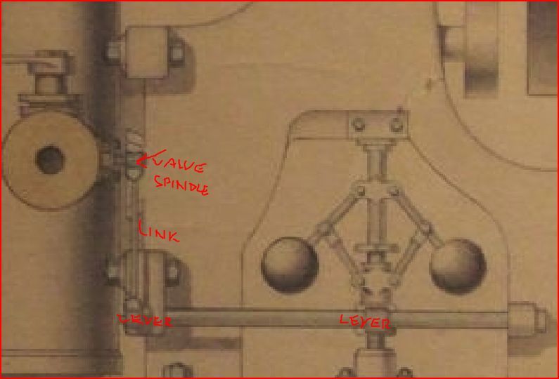
                                            The governor link is visible, that "ring" between the flange from the cylinder and the regulator flange would have a butterfly valve or similar. A lever from the governor to the rocker shaft and then a second lever from the shaft to the butterfly valve complets the linkage. It is there if you blow things up.

                                            aj2.jpg

                                            Edited By JasonB on 25/05/2016 08:38:38

                                            Edited By JasonB on 25/05/2016 08:42:50

                                            #240176
                                            John Fielding
                                            Participant
                                              @johnfielding34086

                                              It could be a type of sleeve valve engine. The sleeve is connected to the piston rod and moves to open and close the ports. As the exhaust seems to be directly opposite the inlet steam pipe that could work. But the piston must have been quite a small diameter compared to the cylinder outer diameter?

                                              #240211
                                              Muzzer
                                              Participant
                                                @muzzer

                                                I expect the port timing would be controlled by suitable holes in the piston skirts, so no need for sleeve valves as such. The piston could be not much smaller than the outer wall.

                                                Although there is no need for a conventional conrod, one of the main downsides of this concept must be the greater stresses on the piston rod. It is subject to significant bending stresses, as most of the thrust is generated when the connecting pin at its greatest off-axis distance. This probably explains the hefty piston rod – possibly hollow but still quite sturdy. And although the piston motion is linear, there will be significant friction generated in the sliding piston rod bearings by the crank / connecting pin.

                                                Murray

                                                #240369
                                                Anonymous
                                                  Posted by JasonB on 25/05/2016 07:24:31:

                                                  PS could you provide one dimension so an idea of size could be worked out, say flywheel diameter

                                                  Jason: Flywheel diameter measures as 7.5". Thanks for the excellent 3D CAD models. It seems that it may well be a viable engine? With your workrate I expect that you'll have knocked one out by the end of the coming Bank holiday weekend. smile

                                                  Andrew

                                                  #240370
                                                  Anonymous
                                                    Posted by John McNamara on 25/05/2016 07:43:33:

                                                    I hope they are framed and hanging on the wall (Not near Sun). Too good to be locked away.

                                                    Yes, all three of my pictures are framed, and hanging in the hall or corridor away from direct sunlight.

                                                    Andrew

                                                    #240371
                                                    Anonymous
                                                      Posted by Muzzer on 25/05/2016 07:50:34:

                                                      There definitely seems to be a genetic component to what makes us tick.

                                                      Quite so, although I had no choice about being an engineer as I'm darn all use at anything else. sad

                                                      Andrew

                                                    Viewing 25 posts - 51 through 75 (of 81 total)
                                                    • Please log in to reply to this topic. Registering is free and easy using the links on the menu at the top of this page.

                                                    Advert

                                                    Latest Replies

                                                    Viewing 25 topics - 1 through 25 (of 25 total)
                                                    Viewing 25 topics - 1 through 25 (of 25 total)

                                                    View full reply list.

                                                    Advert

                                                    Newsletter Sign-up