Posted by Ken Weeks on 15/08/2017 10:32:41:
…
I have found a site that gives a schematic and code for a three axis DRO using an Arduino I want to just have one axis "X".
I have attached the code and commented out (//) the bits that I think are not needed for a one axis read out.
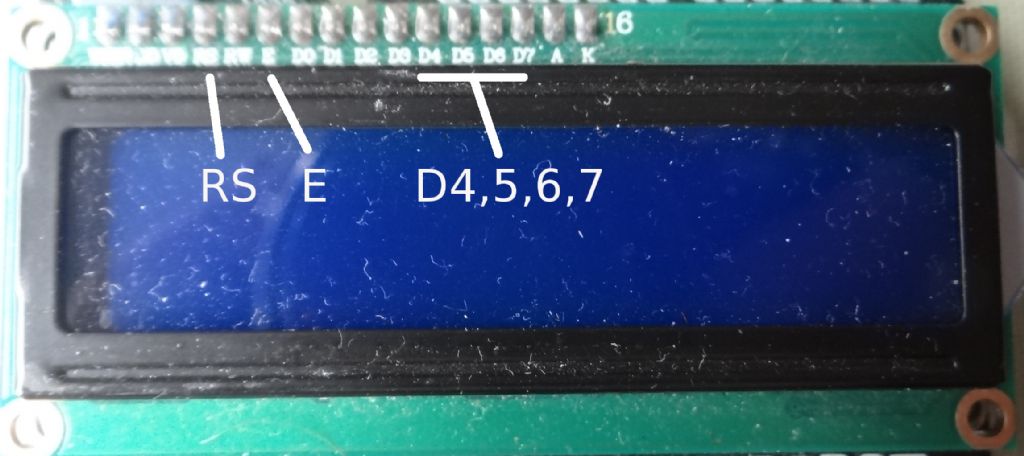
Pins 6 and 7 take the out put from the caliper into the Arduino but I am not sure how to set the out put from the Arduino to the L.C.D.
Is it done by the altering "LiquidCrystal lcd(6,5,4,3,2,1); to read "LiquidCrystal lcd(x.x);" where x.x represents a pair of numbers between 1 and 6 i.e "LiquidCrysyal lcd(1,2);"
…
LiquidCrystal lcd(6,5,4,3,2,1);


  lcd.begin(20, 4);

...
        value|= 1<
Hi Ken,
What you have is very similar to Bob's sketch so it should work. 3 statements need looking at.
First, fix a bug by changing:
value|= 1<to
value|= 1L<Secondly,
lcd.begin(20, 4);
This means that the connected LCD will have 20 characters on each of 4 lines. If your LCD is the more common type with 16 characters on 2 lines type, change the statement to:
lcd.begin(16, 2);
Thirdly,
LiquidCrystal lcd(6,5,4,3,2,1);
This defines which pins on the arduino the display will be wired to. It means:
Pin 6 on the Arduino will be connected to 'RS' on the LCD
Pin 5 on the Arduino will be connected to 'E' on the LCD
Pin 4 on the Ardulino will be connected to D4 on the LCD
Pin 3 on the Ardulino will be connected to D3 on the LCD
Pin 2 on the Ardulino will be connected to D2 on the LCD
Pin 1 on the Ardulino will be connected to D1 on the LCD

I'm not keen on that because Pin 1 is also used by the Arduino's Serial Interface. There will be bad behavior if you try and use the Serial monitor. Instead I'd use 7,6,5,4,3,2 e.g.
LiquidCrystal lcd(7,6,5,4,3,2 );
Also, because the caliper is already using pins 7 and 8, we should move the clockpin. That is change,
int clockpinX = 7;
to
int clockpinX = 9;
and move the caliper clock connection from pin 7 to pin 9 on the Arduino.
Hope that makes sense.
Dave
Edited By SillyOldDuffer on 15/08/2017 11:43:01
Ken Weeks.


