Cromwell S800 drive

Advert

Cromwell S800 drive

Home Forums Manual machine tools Cromwell S800 drive

Viewing 12 posts - 1 through 12 (of 12 total)
  • Author
    Posts
  • #606803
    Andrew Smith 16
    Participant
      @andrewsmith16

      I have finally managed to acquire a Cromwell S800. What a delight – though I now appreciate the warning Mr Wootton gave me regarding the peculiar controls. Lets see if I can manage to retrain my aging brain . . .

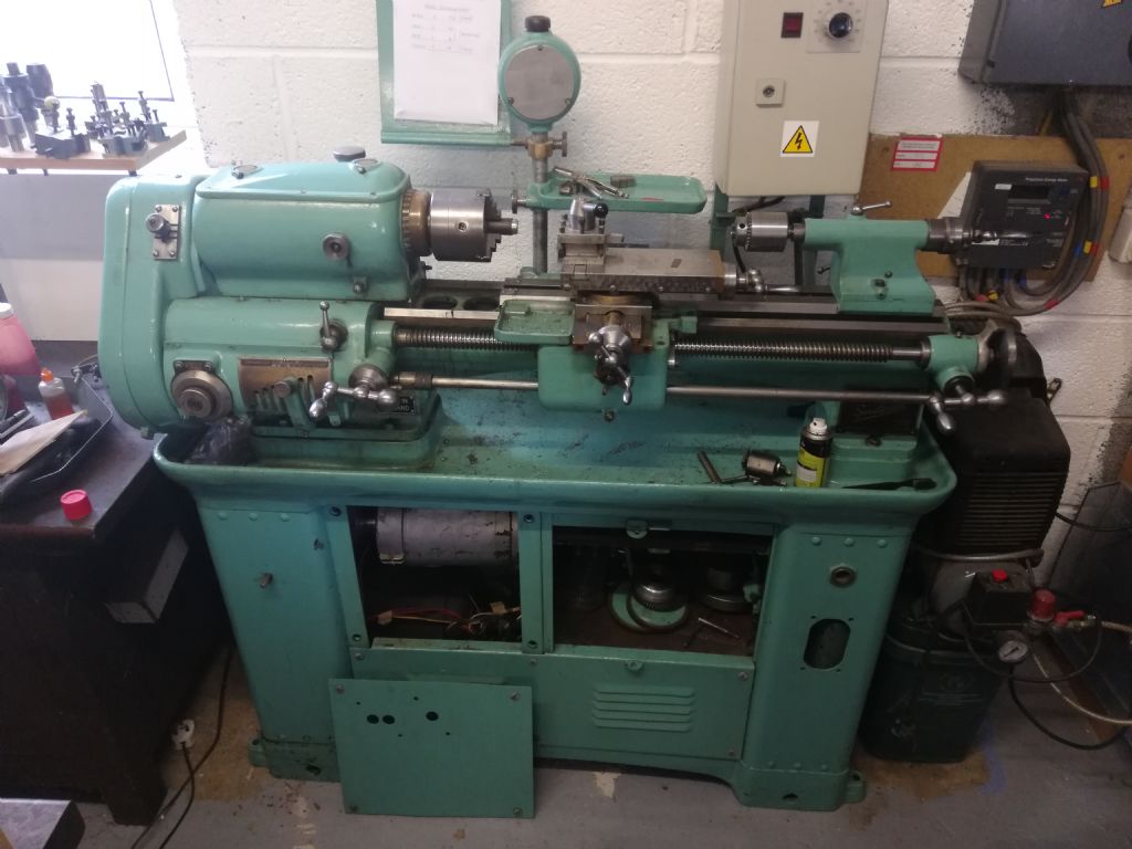
      As might be expected after all these years the machine isn't still completely original and now benefits (I think) from a more modern variable speed drive system. Presumably one of the 3ph jobs so popular among users nowadays. I was expecting big things re the statements made about "no loss of torque at low speeds' etc.

      Some picture attached may or may not help. Not easy getting anything decent in the gloom of the garage today.img_20220721_164007.jpg

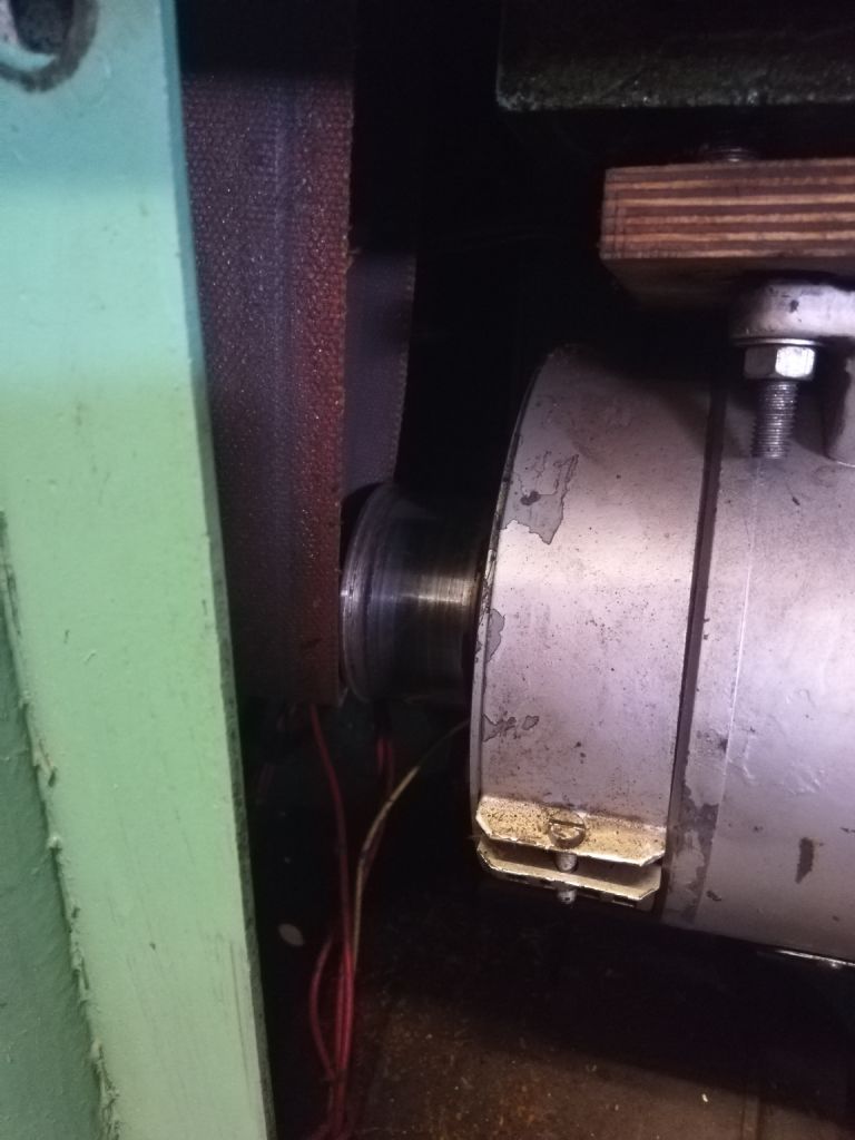
      Sure enough it runs much more quietly than my clunky S7 but I was surprised that it could not manage more than a 5 thou cut in steel without slipping. My preferred solution – turn up the speed and crank the cutter in a bit further to kill or cure the problem, well, killed it. Machine stopped running – providing a reason to pop off the panels and dig around. The problem is pretty obvious but I would appreciate some guidance before I commit to a solution. I am mindful that there are far better brains than mine on this forum.

      The big motor in the picture (silverish colour) looks to have the right size drive pully and looks to me to be basically aligned with the relevant section of the spindle. It is clear that when power is applied and the belt tensioner is tweaked there is enough slack in the system to allow the belt to work itself loose. This is where I request a 'best' solution from the forum.

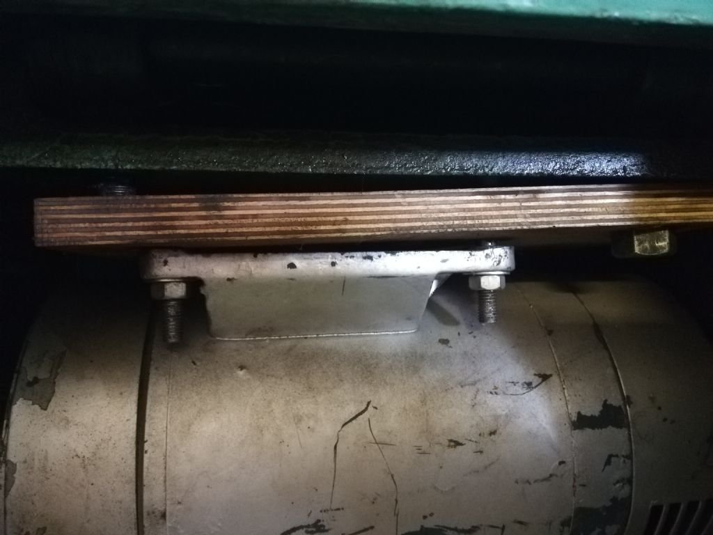
      img_20220721_164026.jpg

      The motor itself is mounted on a piece of plywood that is past its prime but basically sound. That piece of plywood is thence mounted on the original mounting plate of the machine drive. At least one of the bolts holding the plywood to the original mount has come adrift allow a 1/4" or so of play/wobble up and down and back to front in the system. Presumably that is enough to allow the flat belt to walk off the end of the pulley notwithstanding the 1/8" flange on the end.

      img_20220721_164017.jpg

      In a perfect world someone with more experience than me will simply say "replace the missing bolt or bolts between plywood and base plate and double check all other fixings are secure and all will be well."

      Alternatively this is a lash up waiting to cause a bigger problem so maybe I need to do more? What additional things should I be looking for? What would the absolute best solution be?

      I am not going to change the motor. It runs fine but I very much doubt it is the original.

      Are there alignment considerations between the motor pulley and the headstock drive shaft over and above the obvious one that they align in the vertical plane?

      The drive belt is the old 1" variety with a pinned connection. Is it worth changing that as a belt and braces job after securing the motor more thoroughly?

      Any assistance gratefully received.

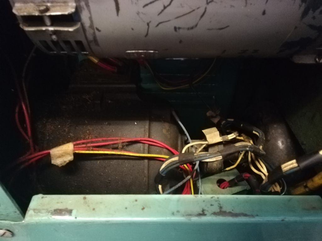
      As an aside the basics of the original drive system remain. Presumable the two massive motors in the base are now redundant (I know that is a simplistic description)? Can I assume the new variable speed control bypasses the old tech – it all looks pretty crusty – allowing me to strip out and salvage the old parts?

      img_20220721_164035.jpg

      Many thanks

      Andrew

      Advert
      #14620
      Andrew Smith 16
      Participant
        @andrewsmith16
        #606844
        Howard Lewis
        Participant
          @howardlewis46836

          How is the plywood base attached to the machine proper?

          Often, having the motor mounted on a platform that pivots allows the weight of the motor to apply sufficient tension tom the belt to prevent slip, but acts a safety device in case of an overload.

          I have seen such a platform pivot on a couple of brass door hinges!

          (It certainly functioned quite well on my ML7 and does on my BL12-24 )

          Howard

          #606858
          Dave Wootton
          Participant
            @davewootton

            Hi Andrew

            Lathe looks to be in great condition, hope you get used to the "odd" controls, I did find it difficult probably just because I was using conventional machines at work. Perhaps I should have persevered, but after spoiling a couple of things that had a lot of time invested in them I did despair a little, a visitor to the workshop made an offer I couldn't refuse for it.

            As regards the belt drive I'm assuming it still has the flat belt drive, can't see from the pictures, if so it is quite critical that the motor shaft and spindle are truly parallel to each other and in line with each other as if viewed from above. It's only the crowning of the pulleys that keep the belt on, the original motor bracket is a substantial affair as the DC drive motors are extremely heavy, so if everything is bolted up tight it should be ok, the plywood spacer looks quite rigid, you may have to experiment with shimming the motor to get the shaft and spindle parallel. I found the original aged leather belt that came with mine prone to slip and replaced it with a new green synthetic one supplied by Tony at Lathes UK it came cut to length and pre scarfed, and has to be joined on the machine using a heat setting glue (supplied). you can hire a heat joining tool but I just used some substantial chunks of heated steel and a digital non contact thermometer and it worked ok.

            I got rid of all the old and very heavy motor and dynamo in the base, but don't scrap them the old generator on mine is on the front of a large scale showmans engine now disguised as a vintage generator! Good luck with it, doesn't sound like anything terribly wrong just needs the drive setting up carefully.

            Dave

            Edited By Dave Wootton on 22/07/2022 07:31:51

            Edited By Dave Wootton on 22/07/2022 07:33:27

            #606860
            Martin Connelly
            Participant
              @martinconnelly55370

              My lathe has a motor mounted on a hinged plate. The belt is much like yours, the spindle pulleys are crowned to keep the belt running centrally. When I took out the original motor to put in a modern one (didn't want VFD spikes killing the old motor bearings) the reduced weight caused problems with the belt slipping. I put a couple of bars of about Ø60 x 150mm stainless (because I had them lying about) on top of the motor for added weight. That fixed it.

              Martin C

              #606862
              Dave Wootton
              Participant
                @davewootton

                The motor platform on my version was tensioned both up and down by the adjustment knob behind the headstock, it sounds like some versions may rely on the weight of motor for tension. If yours is like this then Martin seems to have hit the nail on the head. I believe mine was a very early model, came from Air Ministry Cardington according to a brass plate on the base.

                There are quite a few subtle differences over the production life of these machines, mine had Neco motors, but have seen another with SEM electrics that was very differently arranged, and another with a combination of SEM and BTH motors /generators. One I saw had a different tailstock casting although the rest of the tailstock was the same. Sorry anorak mode there!

                Dave

                #606870
                Clive Foster
                Participant
                  @clivefoster55965

                  +1 to Daves comments on needing to get the two flat belt pulleys accurately aligned and parallel in both directions.

                  I've no experience with the Cromwell but, in other applications, I found it essential to have solid, shake free pivots if hinged plates are used for adjustment.

                  Ordinary hinges don't cut it. Nor do simple bolts in holes unless the pivot drilling is quite long and carefully finished. Best to do a properly fitted shoulder bolt assembly, more work but it should be possible to do all the critical stuff out on the bench where you can get at things for a straightforward job.

                  Fiddling about in situ to get a small bolt in large holes adjustment just so with neither space to work or a line of sight to see gets old fast. Once was quite enough for me.

                  You can get ball bearing hinges that are essentially shake free and well up to the loads. I got a pack of stainless steel EuroMax ones at a very attractive clearance price for a project. Very impressed with the quality. Details at :-

                  **LINK**          https://www.carlislebrass.com.

                  I imagine the proper price is "not cheap" but the £2.50 each I paid was excellent value!

                  I've found an effective way to get slack free, stiff but moveable, pivots is to force thick wall rubber hose into short sections of steel tube having ears welded on for fixing purposes. Car heater hose worked well for me. Inch or two long does the deed. Stiffness of the pivot depends on how tight the hose force fit in the tube is and the diameter of the inner shaft. Don't make the tube fit too tight or its near impossible to insert. Leave the rubber a bit overlong and add large washers to control side play.

                  Easy to get stiffness from gentle push to heave hard with no shake by varing the inner shaft diameter. Use red rubber grease.

                  Brucie bonus is a modest, but useful, vibration absorbtion capability.

                  I'd loose the plywood and do a proper "forever" job. Not something you want to revisit.

                  Clive


                  Edited By Clive Foster on 22/07/2022 10:15:13

                  #606989
                  smf
                  Participant
                    @smf

                    Andrew – I have an S800 too. As others have suggested, I'd get rid of the plywood. I assume that it is only there to act as a mounting base for the motor to biolt up to the original mount because the biolt holes don't line up. I'd replace it with an aluminium or steel plate, and that should be a permanent fix. The original mount is a very heavy iron casting with substantial hinges. It would be worth checking it over to make sure nothing is wrong with it once the motor is out. It also sounds like the belt ineeds to be replaced. I bought a new one from Tony at lathes.co.uk and it was a big improvement over the old one I had. Also, check the drive pulley in the headstock to make sure that oil hasn't found its way onto the pulley – the gasket in my headstock seems to allow oil to leak everywhere, but fortunately not into the drive pulley chamber. You don't say but I assume the motor is 3-phase with a VFD. If so, then yes it is not the original motor which was a DC motor, and the AC motor and DC generator in the bottom can be removed. However, if you'd like an original DC motor and get the system working again, then PM me as I have one to get rid of. Finally, you don't say what size your current motior is. I have a 1/2hp 3 phase motor and I think it struggles a bit in tougher metals. My original DC motor was 1hp and so that's what I'll change to when I get round to it.

                    Stephen

                    #607028
                    Andrew Smith 16
                    Participant
                      @andrewsmith16

                      Thank you so much gents. All points duly noted.

                      Thanks for responding Dave. Our previous correspondence on these machines was useful. Luckily I am a bodger with no formal training so I have less to forget. So far the twin handles have proven useful to maintain an even cut – but I need to get used to the sliding and surfacing features to really make the most of the new toy.

                      Martin – exactly the points the likes of me need to now. I think the existing motor is massive enough without extra weight and, I think, well aligned. I nipped up all of the existing nuts and bolts and added a few clamps between pully and casting. Even with what is clearly a belt that is well past its prime the machine sang through a 100 thou cut without complaint. By my standards that is an industrial size pass – I usually wince at anything over 20 thou in steel. I need to read up on your vfd comments and the effect on bearings. Something else to worry about!

                      Clive – I need to takes things apart to really understand what is going on. My hope is that the machine's original high quality spec means I won't need to do much with the hinges etc. but thank you pointing me to a best possible solution if I need to go down that route.

                      Stephen – I can't see any of the details re the motor so can simply say it is as big. The comment above re a .1" cut means it is as a heavy as it needs to be. Having said that I need to qualify it – IS IT as big as it needs to be? I will take it apart to gather more details then possibly revert. Thanks for the thought re the drive system. For the moment I will stick with the current set up.

                      I am always impressed by the way you more experienced guys blithely suggest swapping the motor or changing the mounting plate for steel. I have no qualms about the process – simply undoing a few bolts – but I get palpitations at the prospect of manhandling what is, to me, a massive motor in an enclosed space. Got to respect the experience of those that have done these things often enough not to be fazed by the prospect of juggling something big enough to snap my puny girl-sized arms if/when it slips! But the point is well made. I'll replace the ply with a steel or alloy plate soon.

                      I will aim to replace the belt too. The thought of hot joining a synthetic belt fills me with dread. The current flat belt is joined with a comb and pin at each end resulting in a ticking as the belt rotates. Eliminating that ticking would be good but . . . more worries.

                      If I try to commit to the synthetic belt how hard is it connect the ends in exactly the right plane? I have joined a lot of watchmakers round belting and have often ended up with quite jaunty angles which aren't a massive problem in V pulleys. Getting a flat belt absolutely bang on straight seems riskier for the likes of me. Should I just go for flat belts and a pin/comb (not sure what the tech terms is). No need to answer.

                      Many thanks once again for your help. Lets see how the repair pans out. Worst case scenario I sell the lathe as scrap in the classifieds. Watch that space.

                      Andrew

                      #607034
                      Clive Foster
                      Participant
                        @clivefoster55965

                        Andrew

                        When making a glued up joint in a flat belt, especially a modern belt, its pretty much essential to use some sort of press to get the joint straight and ensure full contact at the glue line. Having to work inside the machine because the belt has to be passed through the headstock before joining makes things a bit harder.

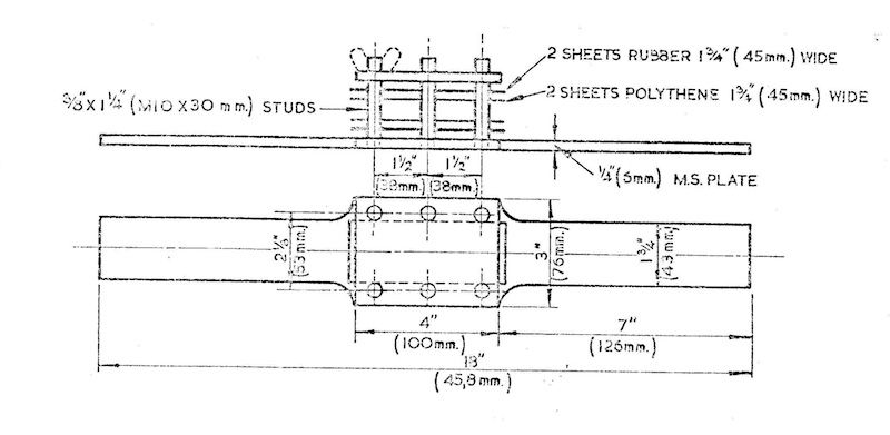
                        This is the press design presented in the Smart & Brown instruction manual for use when joining belts on my 1024 VSL. Its pretty typical of the breed. Many DIY versions omit the long tail each side of the actual press area. Makes the device easier to handle but objectively something of a mistake as the long tail makes it easier to get the belt dead straight. The Smart & Brown design is deceptively large needing approaching 2 ft of clear, straight, belt length to use.

                        belt joining press.jpg

                        The rubber sheets help give an even pressure over the joint. No thickness is given but I imagine something over 1/8" is desirable. The polythene is essential to ensure the belt doesn't end up glued to the press. I often use Duck Tape or similar stuck to the face of things used to support a glueing job for similar purposes. Advantage of tape is that its one less loose component to fiddle with. A one hand clamp or two, such as the big plastic croc clip style or or smaller version of the cartridge gun style ones may help.

                        Its advisable to do several dry runs out on the bench first to nail the technique down. Do remember to orient things in the same way as you will be working on the machine. I'm not the first person to bench practice a technique that was unworkable in practice. Ooops!

                        Some sort of plaining guide is desirable to help get a straight, even scarf.

                        Old style scissors type car jacks can be useful when supporting motor and similar cumbersome weights in restricted places. Whether directly or operating on one end of a suitably long plank or similar whose other end supported by something solid on the other side of the object being moved. I grabbed 4 SAAB 900 ones for peanuts back in the day. Nice thing about those is that the actual lift plate is quite large and already drilled for bolting the object or an appropriately shaped support to it for extra security. The SAAB lift plate is bent giving two flats at an obtuse angle, 120° or so, which is an advantage about as often as it is a disadvantage.

                        It is not advisable to use loose levers held down by a temporarily unoccupied body part when using your hands to deal with nuts, bolts, fastenings and other stuff that is just in the way. Even an octopus is likely to run out of arms (and suckers) half way through such operations. Much less stressful to have a solid support with screw adjustment that will stay put whilst you contemplate your next move.

                        Clive

                        Edited By Clive Foster on 23/07/2022 16:09:58

                        #607037
                        Andrew Smith 16
                        Participant
                          @andrewsmith16

                          That is useful Clive. Even I can manage one of those.

                          But.

                          Are you suggesting that there is a glued option to link the belting? I am only used to hot jointing which I find can be a bit hit and miss.

                          Also – I had anticipated taking the ends well above the headstock for actually jointing then dropping the belt down to loop around the motor rather than juggling around in the confines of the cabinet.

                          Andrew

                          #607047
                          Clive Foster
                          Participant
                            @clivefoster55965

                            Andrew

                            There are indeed glues for belt joining. Whether a more general purpose type suitable for that job among many others or a stickum stuff especially for the job. I imagine modern synthetic belt suppliers will advise on the best type for thier particular belt.

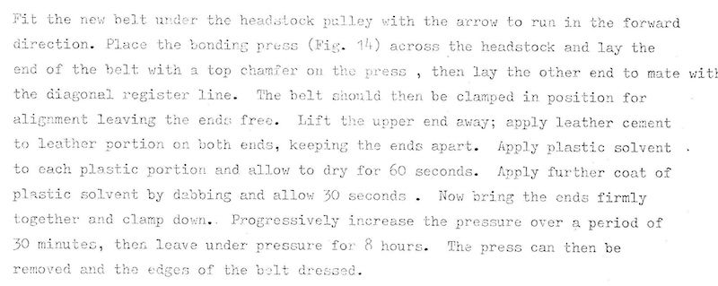
                            Here is what Messrs Smart & Brown advise as an appropriate technique for joining their belts, leather and composite in those days.

                            belt joining.jpg

                            I imagine makers of more modern belts will advise a similar technique with their recommended adhesive

                            Making the joint in clear air above the headstock is clearly the best way of going about things.

                            If using a press like the Smart & Brown one I'd consider curving the tails to give a nicer support to the belt as it enters the press. It might well make life easier if some sort of rigid support for the press could be contrived so you have a solid base to work off. The Smart & Brown has a nice flat joint face, well clear of any pulleys, on which the headstock cover sits so its convenient to lay their press straight across it. From the pictures on http://www.Lathes.co it appears that the Cromwell layout is not so convenient so a support somewhat higher may work better.

                            Clive

                          Viewing 12 posts - 1 through 12 (of 12 total)
                          • Please log in to reply to this topic. Registering is free and easy using the links on the menu at the top of this page.

                          Advert

                          Latest Replies

                          Home Forums Manual machine tools Topics

                          Viewing 25 topics - 1 through 25 (of 25 total)
                          Viewing 25 topics - 1 through 25 (of 25 total)

                          View full reply list.

                          Advert

                          Newsletter Sign-up