Colchester Student Mk1 Won’t Start

Advert

Colchester Student Mk1 Won’t Start

Home Forums Help and Assistance! (Offered or Wanted) Colchester Student Mk1 Won’t Start

Viewing 25 posts - 601 through 625 (of 797 total)
  • Author
    Posts
  • #485454
    SillyOldDuffer
    Moderator
      @sillyoldduffer

      Excellent progress Richard, and Brian's engines too:

      Drool!

      I might manage the shelves, but only if the customer wanted an artistic slope…

      Advert
      #485461
      Phil Whitley
      Participant
        @philwhitley94135

        Donovan, Can you take a pic of the fromt of the lathe please showing all the controls on the headstock. Are you lifting the main start stop lever up to start the main motor, it does not start from the electrical control panel like the coolant pump does? Have you got a manual? I can send you one if you PM me your email address. Take a pic of the whole front of the lathe so we can see what we are dealing with! there are three main types of Student lathe, and several variations of each.

        Phil


        Edited By Phil Whitley on 13/07/2020 19:06:41

        #485471
        Herman van der Merwe
        Participant
          @hermanvandermerwe76509

          All the manuals are here – https://colchesterlathe.groups.io/g/main/files/Colchester%20Student

          Edited By Herman van der Merwe on 13/07/2020 19:41:07

          #485472
          Richard Kirkman 1
          Participant
            @richardkirkman1

            There's the video for the chuck. Not very sticky at all.

            Eclipse Minor Mag Chuck Video

            Do I need to contact Eclipse or is there a proper website for it?

            Donovan, your lathes electric bits look much better than mine did. They look fine to me. But Phil knows best!

            I agree with Phil, pictures of the whole lathe, and a good read of the manual. I'd also recommend reading the 2 pages on lathes.co.uk if you haven't already

            LINK

            #485473
            Donovan Kaardal
            Participant
              @donovankaardal43990

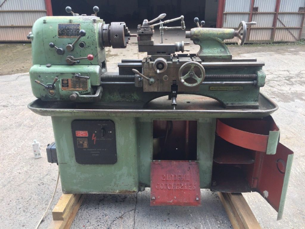
              Here's what the critter looked like when I bought it. It's very slightly cleaner now, but no so much so that you'd notice…

              I do have the manual, and I've practically memorized the lathes.co.uk info on it (amazing resource that site! Expensive though. Just last week it took all the money in my bank account without warning. Though on an unrelated note I am getting an new(old) Schaublin 13 delivered this friday!)

              01.jpg

              #485474
              Phil Whitley
              Participant
                @philwhitley94135

                Right, Mk1.5 gap bed , on the front of the headstock the red knob is the start lever, and the shorter black one in the centre of that is the reversing lever. Make sure the red knob is in the down position, switch on the power, set the rotary switch to main motor, and lift the red knob into the run position, and tell us what happens, any noises etc.

                Phil

                #485477
                Herman van der Merwe
                Participant
                  @hermanvandermerwe76509
                  Posted by Donovan Kaardal on 13/07/2020 19:56:25:

                  Here's what the critter looked like when I bought it. It's very slightly cleaner now, but no so much so that you'd notice…

                  I do have the manual, and I've practically memorized the lathes.co.uk info on it (amazing resource that site! Expensive though. Just last week it took all the money in my bank account without warning. Though on an unrelated note I am getting an new(old) Schaublin 13 delivered this friday!)


                  01.jpg

                  That is a Mk1.5 Student.

                  Check the ON/OFF switch on the back if it locks into the final ON position and if there is continuity over the contacts. If so, check if the main contactor has continuity over each contact when manually depressed, Then check the two isolation switches for continuity. I would simply bridge the switches out on the instrument panel to get the motor to live.

                  Schaublin 13 = Watching to much TOT. Congrats, wish I could get one this side of the round blue thinghy.

                  Edited By Herman van der Merwe on 13/07/2020 20:15:39

                  #485484
                  Donovan Kaardal
                  Participant
                    @donovankaardal43990

                    Hi Phil,

                    That's the process I've been trying. Handle with the red knob at it's lower position, turn power on at the grey box on the left hand side of the picture above, rotate the MAIN MOTOR dial from OFF to ON, then left the handle with the red knob to the up position.

                    No sound other then the mechanical click from the switch box at the back of the lathe:

                    20200713_175124.jpg

                    There's no hum of any kind, not even from the motor itself.

                    The only time there's any noise is when I turn the dial to MAIN MOTOR + PUMP, then the pump makes a whirling sound.

                    I used my multimeter to test continuity between the grey panel on the side where the 3 phase power comes in to the sockets where those 4 big brass prongs on the back of the main panel plug in. Only 3 are connected to anything, but there's continuity between the 3 live wires in the grey box to the 3 sockets that line up with the 3 prongs that have wires attached to them.

                    Lord I hope that makes sense.

                    #485487
                    Richard Kirkman 1
                    Participant
                      @richardkirkman1
                      Posted by Herman van der Merwe on 13/07/2020 20:13:39:

                      That is a Mk1.5 Student.

                      Check the ON/OFF switch on the back if it locks into the final ON position and if there is continuity over the contacts. If so, check if the main contactor has continuity over each contact when manually depressed, Then check the two isolation switches for continuity. I would simply bridge the switches out on the instrument panel to get the motor to live.

                      Schaublin 13 = Watching to much TOT. Congrats, wish I could get one this side of the round blue thinghy.

                      Edited By Herman van der Merwe on 13/07/2020 20:15:39

                      No such thing as too much TOT. Coincidentally TOT also has a student mk1.5

                      I'll just let Phil take over the electrical troubleshooting since I only just understand it myself.

                      I'd be interested as to why they went from 3 pins to 4? Especially if one of them does not have anything coming from it.

                      #485488
                      Phil Whitley
                      Participant
                        @philwhitley94135

                        Yes, perfect sense, is your multimeter good for 240 volts, If so you need to check with the power on, the red knob in the down position, the yellow wire in the switch at the back should be live. and you need to check that the lathe is properly earthed as you will be uing the chassis of the lathe as a neutral point for the purpose of testing., test between the yellow wire terminal and the chassis of the lathe. Whilst you can use a multimeter for this, set to 500v, if you are not confident about safety, get a mains tester like a Martindale VT12 (google it) and use that instead. If the yellow wire is live, the fault is in the switch or further downstream, if the yellow wire is not live, either the key switch or the end cover switch are not closed, or are faulty.

                        Phil

                        #485490
                        Phil Whitley
                        Participant
                          @philwhitley94135

                          Actually you could test this with the power off and unplugged, connect one multimeter lead to the yellow wire in the switch, switch on the isolator (grey MEM box), set the rotary switch to main motor, and with the red knob in the down position, probe the three pins in the plug, you should get continuity between one of the pins and the yellow wire.

                          Phil

                          #485516
                          Donovan Kaardal
                          Participant
                            @donovankaardal43990

                            Thanks Phil, I'll try that first thing tomorrow morning.

                            I've been doing mainly continuity testing with the power disconnected rather then while everything is live since I don't know if the machine is grounded. The Yellow/Green from the incoming line is tied to the grey box (isolator?), but I don't know that the motor is tied to that anywhere so I have to assume it's not grounded. Meaning I'm very careful when I do apply power and try that switch. All other times the machine is unplugged.

                            As for ToT, I have to admit I've watched pretty much all of his videos. Which is impressive, since I only discovered his youtube channel about a week or so ago!

                            #485635
                            Donovan Kaardal
                            Participant
                              @donovankaardal43990

                              Running the tests that Phil suggested gave me some puzzling results.

                              With the power disconnected, I tested continuity between the plug pins and the yellow wire at the switch at the rear of the machine. There was about 1.3 Ohms resistance, so I'd get an interrupted tone (tone sounds when you touch the contact, then stops.).

                              I decided to check it under power. I connected one lead to the isolator box and then touched each of the wires at the switch in turn. I'd thought I'd had the red knob in the down position, but looking at my notes I suspect it was in the up position. Here's what I found on my multimeter (Fluke 115)

                              voltage.jpg

                              I did remove the two interrupt switches just in case – I just tied the wires together, since both switches seemed to be wired to Normally Open.

                              I pulled the switch off of the back of the machine and I've brought it home. Not sure if it's the problem, but it desperately needs a good cleaning anyway. Once I've stripped and cleaned it I'll see if there's any wear on anything. If not, I think it'll be time to dissect the motor.

                              #485653
                              Phil Whitley
                              Participant
                                @philwhitley94135

                                Right!! Donovan, no point in looking at the motor, the power is not getting that far, when you lift the red handle, the main contactor should pull in and they make quite a loud thump, so we have another fault. You have proved that the coil in the main contactor is present and ok though, as the 240v you read on the red terminal is fed from a phase, through the coil , tnrough the overload cut out contacts, and on to the red terminal at the switch at the back. The yellow wire is supposed to supply the other phase to the switch, and when switched, pull the coil in and energise the main contactor.

                                The two switches should be normally closed when the end cover is fitted, and the key switch is on, so you need to connect the two yellow wires electrically together at the cover switch position and the key switch position, you should then be able to test the yellow wire from inside the control panel and the yellow wire in the switch and get continuity. Once you have established this, you need to check for continuity between an incoming phase and the yellow wire in the contactor panel, put one test lead on the yellow wire terminal on the contactor, and one on the brass pins on the contactor board input "plug" one of the pins should connect to the yellow wire, if not, that is the fault!

                                It appears that your main contactor is slighly different to mine (and richards) but the wiring is the same for all.

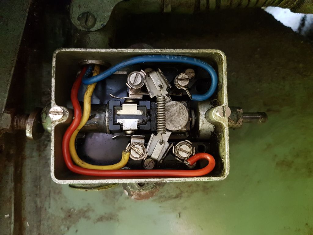
                                If you are working on the switch from the rear of the headstock, note that it is actually a three position switch, as it moves through an intermediate position as you move the lever from down to up.. Note also that terminalls at the right of the switch are linked.

                                In the off position the bottom two terminals are closed and the top two are open.

                                in the intermediate position the bottom two terminals are closed AND the top two are closed. this gives continuity from the yellow wire terminal across the top to the link, down the link and across the bottom two terminals to the red wire .

                                In the on position, the top two terminals remain closed, but the bottom two are open.

                                When you have confirmed this with a multimeter, the switch is working correctly.

                                I am going to have a closer look at the pics of your contactor and get back to you! I am on the forum every night, and all weekend because I have no life!

                                Phil

                                #485659
                                Phil Whitley
                                Participant
                                  @philwhitley94135

                                  On the main contactor, A1 B1 and C1, go to the motor, so testing for continuity between those three confirms the motor windings are good.

                                  L1 L2 and L3 are the phases (lines) coming in from three of the four brass pins on the plug, via the rotary switch. Check for continuity between the yellow wire terminal and the black wire terminal next to it. It looks like the black wire snakes around to the Line side of the contactor, and picks up a phase (check this). If there is no continuity between yellow and black, it looks like the overload has tripped, or has had a bump and needs resetting. On the side of the bit where the yellow and black wires are, there is a red and white label, can you take a pic of it, and that whole side of the contactor pls?

                                  Earthing!! Earthing is very important, especially when you are dealing with a machine whose condition is not known, if the machine is properly earthed, and there is a motor winding fault, a fuse will blow, or a trip will operate or the overloads in the machine itself will cut the supply to the motor. If the machine is not properly earthed, the whole case of the machine will become live with repect to earth, and anyone touching it will recieve a potentially fatal shock! You can confirm the earthing by testing from a live point, to the case of the machine with your multimeter, and you should get a full 240volts. If you do not the machine is not earthed, and you should not carry on untill this has been rectified!! this also confirms that the earthing in the building, or at least, the socket you are connected to is good, and it may even cause an RCD to operate, although I think the flukes are fitted with circuitry to prevent this. MAKE SURE IT IS PROPERLY EARTHED!!!

                                  Phil

                                  Edited By Phil Whitley on 14/07/2020 21:05:11

                                  Edited By Phil Whitley on 14/07/2020 21:06:14

                                  #485676
                                  Donovan Kaardal
                                  Participant
                                    @donovankaardal43990

                                    I'll get some pics tomorrow morning for you Phil, and I'll take some readings on the contactor tomorrow as well. Thanks for your help with this!

                                    When I was taking the voltage readings, I had one probe on the wire and the second probe on the machine itself. That seems to indicate that the machine is grounded, though I'm still puzzled with the 11.6v readings on some of the wires at the switch on the back.

                                    #485709
                                    Herman van der Merwe
                                    Participant
                                      @hermanvandermerwe76509
                                      Posted by Donovan Kaardal on 14/07/2020 22:33:38:

                                      I'll get some pics tomorrow morning for you Phil, and I'll take some readings on the contactor tomorrow as well. Thanks for your help with this!

                                      When I was taking the voltage readings, I had one probe on the wire and the second probe on the machine itself. That seems to indicate that the machine is grounded, though I'm still puzzled with the 11.6v readings on some of the wires at the switch on the back.

                                      That value is typically of a floating neutral or ground in the supply line. Have you checked the supply voltages at the wall outlet? What are the voltages there between L1 & L2, L2&L3 L3&L1 and then, L1 to building earth etc?

                                      I think Richards's thread is now not only hijacked but also morphed …. maybe split and start another thread Mods?

                                      #485748
                                      Richard Kirkman 1
                                      Participant
                                        @richardkirkman1
                                        Posted by Herman van der Merwe

                                        I think Richards's thread is now not only hijacked but also morphed …. maybe split and start another thread Mods?

                                        I think at this point this thread is not on topic much anymore, pretty much just my musing, so may as well keep on it. Or start a new one, whatever is easiest, it doesn't bother me, just as long as people are being helped. This thread is getting very long. Might be able to knit a jumper soon…

                                        I think I'll have to do a full concise write up once this I'm all finished. Same information as here, but shorter and in one place, with no questions. I'm still pestering the woman from the south for the spare parts, it's only been 6 months so I'm sure she'll cave and go get them soonlaugh . Either that or time to give up, back at uni in 8 weeks so the time is slipping through my fingers

                                        #485821
                                        Donovan Kaardal
                                        Participant
                                          @donovankaardal43990
                                          Posted by Phil Whitley on 14/07/2020 21:03:47:

                                          If there is no continuity between yellow and black, it looks like the overload has tripped, or has had a bump and needs resetting.

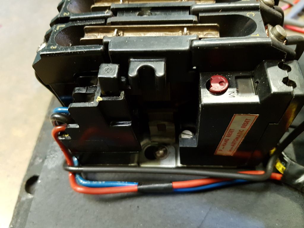
                                          Phil, you were right on the money with that one. I'd though the overload switch/button was fine because it was pushed in… but I checked and there was no continuity between the yellow and black wire contacts. I poked at the overload button and out it popped! Put everything back together and presto! – things started moving!

                                          I'm a little chagrined that I missed such an obvious thing, but I do want to say thanks to everyone for helping. Now I get to put everything back the way it was before I started messing around, and then I get to actually set up the lathe and maybe, just maybe, start doing some turning!

                                          😀

                                          #485856
                                          Richard Kirkman 1
                                          Participant
                                            @richardkirkman1
                                            Posted by Donovan Kaardal on 15/07/2020 16:17:03:

                                            I'm a little chagrined that I missed such an obvious thing, but I do want to say thanks to everyone for helping. Now I get to put everything back the way it was before I started messing around, and then I get to actually set up the lathe and maybe, just maybe, start doing some turning!

                                            😀

                                            Well done Donovan, good luck with your turnings. I knew Phil would sort you out!

                                            Even if it was an obvious thing, I imagine you now know a lot more about how the lathe actually functions than if it had just been plug and play. So you're much better off in the future if something fails. Now you can get it properly set up. I'd recommend Phil's youtube channel on his lathe's headstock alignment videos. Even if you don't align the headstock, it's interesting to see the procedure and learn more about the lathe.

                                            Do you have any plans for what you're going to make?

                                            #485888
                                            Phil Whitley
                                            Participant
                                              @philwhitley94135

                                              Excellent, don't worry about not spotting it, its only obvious if you know what your'e looking for! Your contactor is slightly different to ours, and the red/yellow/blue wires that go to the switch at the back have been swapped at the contactor end to suit the contactor. On the generic student wiring diagram the overload feeds the red wire, on yours the overload contacts feed the yellow wire, the end result is the same, they must have started using a different contactor! I gather the main motor is now running? Also glad you were testing voltages to earth, and thus confirmed the earthing on the machine!!

                                              Well done Donovan, You have advanced a tech level!

                                              Phil

                                              #486037
                                              Donovan Kaardal
                                              Participant
                                                @donovankaardal43990

                                                Thanks Phil and Richard – everything seems to be working, except of course for the interrupt switches I removed. Which I'll now be putting back.

                                                Just for historical purposes, I'll post a pic of the red button that was depressed on the contactor. Poking at it made it pop out, and after that everything worked.

                                                As for what I plan on making… just little things to start with. Mainly small tools or parts for larger tools. I used to have a forge back home, and I loved the flexibility of the 'need a tool, make a tool' mindset. Anything from carving gouges to finger planes, it's handy to be able to make your own tools. Also, knurled thumb screws are strangely expensive, so I think I'll start by learning to knurl properly and get to work making a bunch of those.

                                                Of course after hanging out on THIS website I now also want to make a sterling engine!

                                                😀

                                                reset_sw.jpg

                                                #486124
                                                Phil Whitley
                                                Participant
                                                  @philwhitley94135

                                                  No problem Donovan, that is what we are here for!

                                                  Phil

                                                  #486356
                                                  Richard Kirkman 1
                                                  Participant
                                                    @richardkirkman1

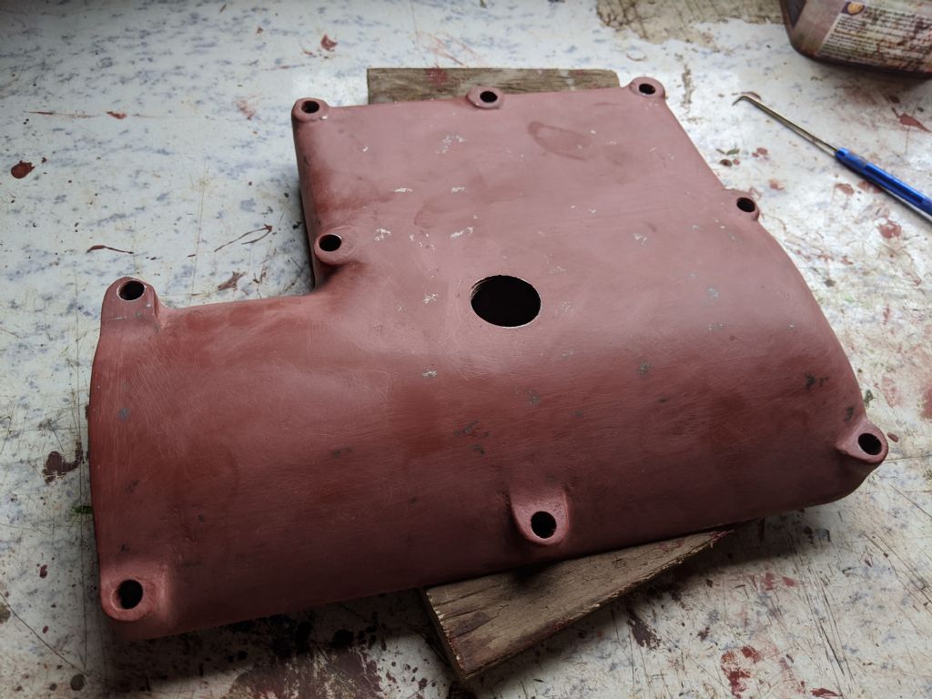
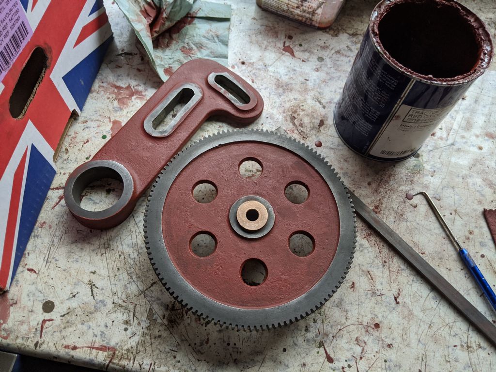
                                                    I've been thinking about a few tasks I'd like to do, a few involving lathe work. With only 7 weeks till I'm back at uni and with the lawnmower to finish too, there's no chance I'm going to get the whole lathe disassembled and painted and finished this summer. So my plan is to paint the few parts that I have off the lathe, then to get the lathe back up and running so I can actually use the lathe for the coming weeks. It'll also make more space to work on the mower.

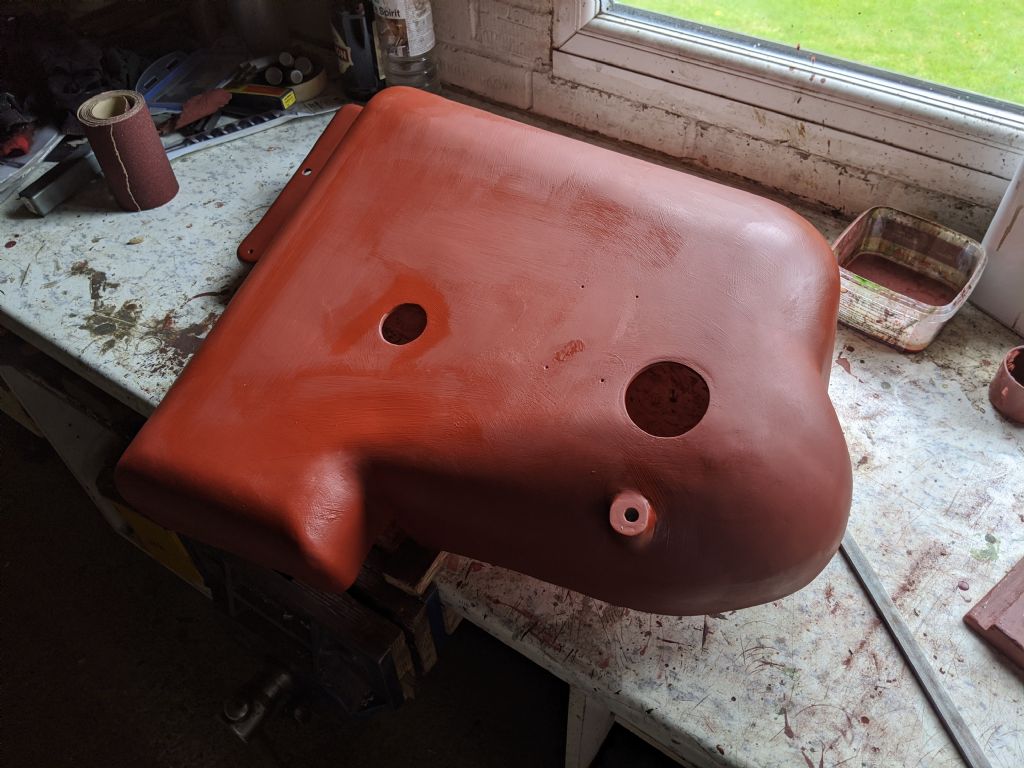
                                                    So I've sanded down the first coat of primer and put a second on all the parts. I'll flatten this off again then hopefully get some grey on them, Not much progress, but its a step in the right direction.

                                                    img_20200717_164032.jpg

                                                    img_20200717_180422.jpg

                                                    img_20200717_192956.jpg

                                                    #486418
                                                    Herman van der Merwe
                                                    Participant
                                                      @hermanvandermerwe76509

                                                      Wise decision Richard. I am going on two months for cleaning and only now have almost all the parts coated in primer. Onto smoothing and filling and sanding and sanding and some more sanding …

                                                    Viewing 25 posts - 601 through 625 (of 797 total)
                                                    • Please log in to reply to this topic. Registering is free and easy using the links on the menu at the top of this page.

                                                    Advert

                                                    Latest Replies

                                                    Viewing 25 topics - 1 through 25 (of 25 total)
                                                    Viewing 25 topics - 1 through 25 (of 25 total)

                                                    View full reply list.

                                                    Advert

                                                    Newsletter Sign-up