Chester Mini Mill – X2?

Advert

Chester Mini Mill – X2?

Home Forums Manual machine tools Chester Mini Mill – X2?

Viewing 21 posts - 1 through 21 (of 21 total)
  • Author
    Posts
  • #53500
    Deril
    Participant
      @deril
      I am advised the transformer has open circuited causing failure of my mill to work.
       
      The numbering shown on the transformer is :-  FT3515-220-14DP
       
      If anyone can suggest where a replacement for this component may be
       
      obtained I would be most grateful. 
      Advert
      #11681
      Deril
      Participant
        @deril
        #53510
        Peter G. Shaw
        Participant
          @peterg-shaw75338
          Hi Deril,
           
          Having read your post, I am left wondering about this because there are a number of oddities.
           
           The way you write suggests that you have very little electric/electronic knowledge as you imply that someone else has done the initial testing. Without trying to be obnoxious etc, does this other person actually know what they are doing? You see, I’m not at all sure that these machines have a transformer in them. Now I could well be wrong, and no doubt someone else will correct me, but the information I have gleaned so far does suggest this.
           
          Another pointer is that historically, the X2 machines did have problems with MOSFET failures, indeed this was one of the reasons why one seller stopped selling them. However, it does seem that there are a number of electronic versions around for these machines, some of which are American designs and which appear to be being used on the uprated versions, and are possibly more reliable.
           
          Now, as regards spares, since it is a Chester MiniMill, why not try Chester themselves? Another possible source that has been mentioned on these boards is Machine Mart. But in either case be prepared for a hefty bill for a replacement board.
           
          If it definitely is a transformer, there is always a remote chance that it might be repairable. It all depends on just where the fault is. It may just be that one of the connections has broken. Now if it happens to be the connection to the outermost winding layer, then it may be possible to unwind one turn, and remake the connection. Very much a long shot, and may be impossible if the winding has been impregnated with something.
           
          Other than that, I can’t help you, so good luck in your quest.
           

          Peter G. Shaw

          #53514
          john swift 1
          Participant
            @johnswift1
            Hi Deril ,
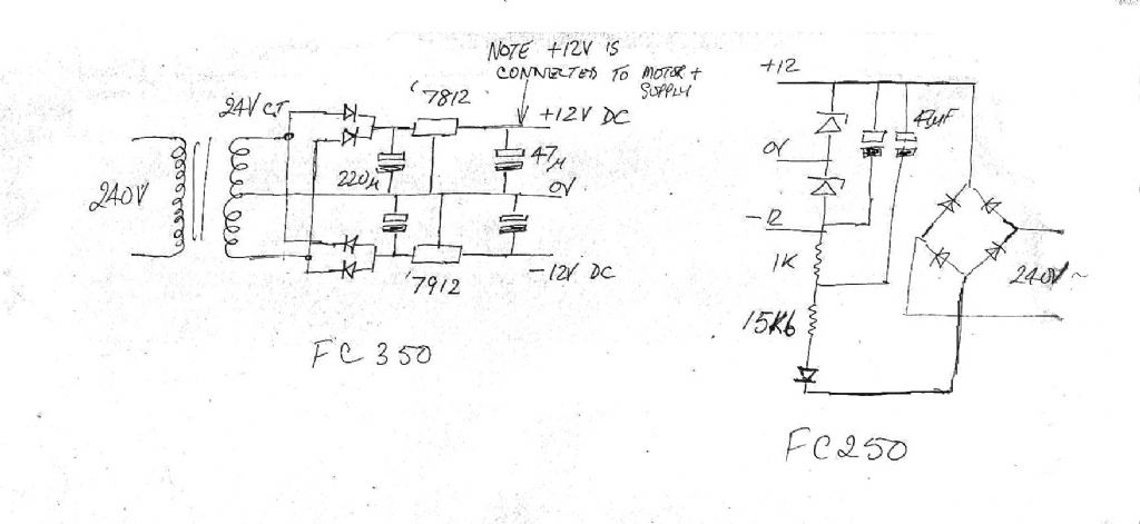
                          Having reverse engineered a FC250J/240v controller of a minilathe
            a short while  ago , and having had  a quick look at a photo of the F350 type of controller in    mini mills
            I would expect a 6va transformer with a center taped 24v secondary would work
            maplin may have one that electrically will do , but you will more likely have to go to rs components ,  rapid  or  cpc for one to fit the board
             
            I would expect any machine supplier like chester .,machine mart etc only to sell
            a new pcb .
             if you can measure the size and pin spacing of your transformer i’ll try to
            give you some part numbers
             
             you will see 3 of my photos are scans of the circuit i drew from my controller
             
                                           John Swift

            Edited By john swift 1 on 18/07/2010 00:15:42

            #53517
            Martin W
            Participant
              @martinw
              Deril
               
              Silly question but is the mill still in the warranty period, if so then I am sure that Chester would be more than willing to help and sort things out. Another approach is to go on the Chester site and place a post on their forum. There are, much as on this forum, particularly helpful individuals who may be able to help.
               
               
              Cheers
               
               
              Martin
              #53527
              john swift 1
              Participant
                @johnswift1
                a good point Martin not a silly question at all !
                 
                after a quick look the nearest result I have found is
                 
                VIGORTRONIX  VTX-120-3803-212   has  a  230V primary and two 12V secondary windings
                 
                farnell  part number 1712701   may not be a drop in replacement but can be made to fit
                 
                                             John Swift
                #53529
                Peter G. Shaw
                Participant
                  @peterg-shaw75338
                  John,
                   
                  Ok, so there is a transformer after all, but your diagrams don’t show it. So where is it?
                   
                  Regards,
                   
                  Peter
                  #53530
                  john swift 1
                  Participant
                    @johnswift1
                    Hi Peter
                     
                                  the speed control on the older mini lathes do not have one  !
                    at the left hand side of the diagram for the main board
                    you will see  two  12v zenner diodes ( D6 D7 ) and dropper resistors   R40 and R41
                    provide a simple  low voltage supply for the two ics used to control the speed
                     
                    on your controller you have an extra circuit to monitor the motor current
                    the third relay you have extra demands more power
                    hence the transformer and 12 regulators you have
                     
                    sorry for any confusion
                     
                    if you need the circuit for you controller I’ll draw and up-load the extra bits not on
                    the FC250 controller but on the FC350 controller 
                     
                     ps     do you have the new board with the surface mount components
                              or the older through hole wire ended components
                              so I can look for a picture of your board

                    Edited By john swift 1 on 18/07/2010 12:13:22

                    #53531
                    Les Jones 1
                    Participant
                      @lesjones1
                      Hi all,
                                 Here is a link I found with some information on the X2 controller board.
                       
                      I think I have seen somewhere that there are several versions ov this board so Deril will need to check that this information is reffering to the version he has. Also he does not say what the fault is with the transformer. (ie open circuit primary or secondry etc) I think he should be sure the transformer is faulty before trying to fit a replacement.
                      Les.
                      #53533
                      john swift 1
                      Participant
                        @johnswift1
                          Hi Les ,
                        thanks for the link  I understand the controller has been used on some mini lathes
                        now save just in case
                         
                        just for information Peter I’ve added the diagram below


                        #53536
                        Les Jones 1
                        Participant
                          @lesjones1
                          Hi John,
                                         Here is a web page with some information as to which boards have been used in which machines.
                           
                          Also I have traced the schematic for the board in the X3 mill. Let me knoe if you would like a copy of the schematic.
                          Les.
                          #53537
                          john swift 1
                          Participant
                            @johnswift1
                            Hi Les ,
                                        
                             I would be interested in the X3 schematic
                            I may buy a X3 milling machine one day.
                             
                            the  link to the sieg control info shows the development of
                            both the PWM control boards , as in my mini lathe
                            and SCR ( controlled bridge rectifier) boards used in some other  machines
                             
                                                      Thank You
                                                    
                                                                      John Swift

                            Edited By john swift 1 on 18/07/2010 15:48:21

                            #53546
                            Deril
                            Participant
                              @deril
                              Many thanks for all the interest.
                              In answer to several of the queries :-
                              The mill is 7 years old and has given very good performance.
                              There is a transformer, the board is double sided, the mosfets are sound and it is the primary which is dud.
                              My other person knows what he is doing.
                              My own understanding of electronics is just one of interest and quite shallow but as with most things in this hobby we like to persue problems the hard way rather than the easy replacement we could do so easilly.
                              The lettering on the transformer could very well be the board designation for which it was destined.
                              The pin placing differs from any of those shown by Farnell, Rapid.RS or Maplin.
                              They are on the same basic grid as the3VA (not the 6VA) i.e 25×20 with the two inputs spaced at 20 and the output three at equal spacing on the other 20 leg.
                              I think the approach now is to use a Rapid chassis mount 88-3416 as close to the board as sensible and see if this is the required fix.
                              The posts by John S have been most interesting and useful and now the ref.-
                               X2 controller provided by Les J adds to my understanding.
                              Regards to all. 
                              #53549
                              Peter G. Shaw
                              Participant
                                @peterg-shaw75338
                                Hi Deril,
                                 
                                As I said: someone will be along to correct me – and they did! And ok, your other person knows what he is doing. Unfortunately, my own experience of some electronics people is that they don’t know what they are doing – I took a tape recorder in for servicing once when I was young and naive – it came back worse than when it went in. Fortunately, a colleague was sufficiently knowledgable to teach me how to put it right myself, and since then I have learned rather more about electronics. Also I have had  experiences in other fields where it has cost me to prove that the so-called experts are not! Hence my scepticism.
                                 
                                As it happens I have the higher powered mill by Warco – John please note – with I think, the American based board. Unfortunately, it being 10 days after an abdomen operation, looking at my mill is temporarily out of the question, but I don’t recall there being a transformer at all.
                                 
                                Never mind, it’s all grist to the mill (ah-hem) and I am learning. I imagine that the system operation should be very similar so all the info gleaned so far should be of help if my own does indeed fail at some point.
                                 
                                One interesting point, John. Looking at the power circuit, I designed and built the identical configuration when I was trying to convert an oscilloscope. Maybe the actual values were not the same, but it didn’t work. As far as I could tell, the 7815 was powering up before the 7915, which faced with power from the 7815 then refused to work. To get round it, I ended up designing a different -ve supply which probably relied on the +ve supply for it to work. It’s along time ago so I can’t remember the exact details, but it did work, although the overall project didn’t. And anyway, a brand new ‘scope solved the problem!
                                 
                                Regards,
                                 
                                Peter G. Shaw


                                Edited By Peter G. Shaw on 18/07/2010 21:31:41

                                #53550
                                john swift 1
                                Participant
                                  @johnswift1
                                  Hi Deril ,
                                                 I think we have all learned some thing .
                                  ( putting our jigsaw pieces together we can all see the big picture  )
                                   the transformer you have chosen will be a good choice .
                                  in the event it does not work  , the info from Les Jones    will provide the solution.
                                   
                                                         Good Luck
                                                                            
                                                                                 John Swift
                                  #53557
                                  john swift 1
                                  Participant
                                    @johnswift1
                                    Hi Peter ,
                                     
                                      take care and don’t undo the hospitals good work , and get well soon
                                     
                                    the ideal way to use the 78xx and 79xx  1 amp regulators as in my simple diagram
                                    is to add a normally reverse biased diodes  from input to output  ( 1N4001 type will do )
                                    and another  one  from output to the ground/ reference terninal on each regulator.
                                     
                                    I have had one regulator oscillate with a square wave output because one of the decoupling capacitors had too high a ESR , all good fun , thats how we learn
                                    just in case you want to know how I measured the ESR
                                    I have built the blue ESR meter kit thats a updated version  of the design in the siliconchip magazine 
                                     
                                    yes you have to be able to distinguish between  those how call themselves experts and those called experts by others
                                     
                                                                                    Take care
                                     
                                                                                                            John Swift
                                                                                                          
                                    #53565
                                    Martin W
                                    Participant
                                      @martinw
                                      Hi Peter
                                       
                                      I can only re-iterate John’s comments about not undoing the work done by the hospital.
                                       
                                      I fully agree with your comments re the ‘EXPERTS’ as I have had similar experiences with so called professionals only to rue the day they entered my home. Most of the things I need ‘seeing to’ now I do myself as I am then sure the work when completed is done properly and nobody is put at risk.
                                       
                                      Take care and have a speedy recovery
                                       
                                       
                                      Martin
                                      #53587
                                      Deril
                                      Participant
                                        @deril
                                        For John S
                                         
                                        After looking at the Les J info I think the output of the transformer should be 15V as it is followed by the voltage regulators for 12V. We will see.
                                         
                                        I wonder if the regulator shown on the schematic as KA9712 has the 9 and 7 transposed?  
                                        #53590
                                        john swift 1
                                        Participant
                                          @johnswift1
                                          Hi Deril
                                                         two things to consider  :-
                                          1,   small transformers output can 10 or 15 % larger  off load , than at maximum load
                                          2,   12v rms when rectified will give you up to 16.9 v dc ( 12 x 1.414 ) across C11 & C12  
                                                  on the diagram supplied by Les
                                                   the diagram indicates this voltage  drops to 15v with the load on the power supply
                                                   this is about the minimum for the regulators to work
                                           
                                                  If I remember correcly the 1 amp regulators need an input of 2 or 3 volts more
                                                  than the expected output
                                                                                                 
                                                   I think the negative regulator will be KA7912
                                          If you search 7812 and 7912 you will find a large number of data sheets
                                              eg National semicondutor part start with LM , fairchild  parts with  uA
                                           
                                                                                                       
                                          note – if the transformer output is too high , the regulators will run too hot without heatsinks
                                                      the metal tab on the 7812 is connected to ground but
                                                      the metal tab on the 7912 is connected to the input !
                                                     
                                                      in this case the transformer does not provide mains isolation
                                          the +12v is connected to the rectified mains from bridge rectifier B1 
                                                                                            
                                           
                                                                                 John Swift
                                          #53591
                                          Les Jones 1
                                          Participant
                                            @lesjones1
                                            Hi Deril,
                                                             I think a 12 – 0 – 12 V transformer will probably be correct. With a capacitor input filter (Which is what the circuit  is.) the DC output will be near the peak voltage of the sinewave which will be 1.414 x 12 = 16.97 The actual value will be a little less than this due to the voltage drop across the diodes and winding resistance. I think you are correct that the 7 and 9 are transposed.
                                            Les.
                                            #53596
                                            Peter G. Shaw
                                            Participant
                                              @peterg-shaw75338
                                              Many thanks to those who wished me well after the operation. Yes, all is going well and I’m only doing what I feel like doing. Any sign of stress, and I back off.
                                               
                                              Fortunately, I can still operate the computer.
                                               
                                              Regards,
                                               
                                              Peter G. Shaw
                                            Viewing 21 posts - 1 through 21 (of 21 total)
                                            • Please log in to reply to this topic. Registering is free and easy using the links on the menu at the top of this page.

                                            Advert

                                            Latest Replies

                                            Home Forums Manual machine tools Topics

                                            Viewing 25 topics - 1 through 25 (of 25 total)
                                            Viewing 25 topics - 1 through 25 (of 25 total)

                                            View full reply list.

                                            Advert

                                            Newsletter Sign-up