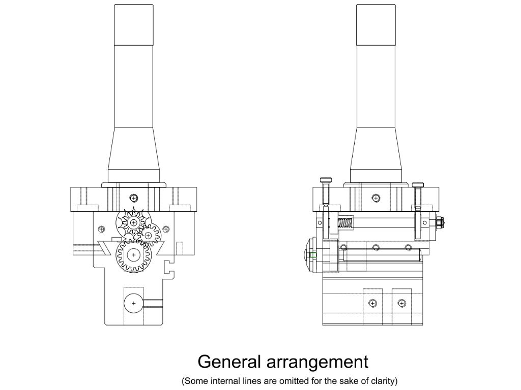
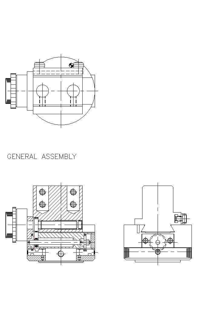
Anyone care to scrutinise some drawings?
Anyone care to scrutinise some drawings?
- This topic has 17 replies, 9 voices, and was last updated 20 January 2016 at 19:46 by
 John Hinkley.
Viewing 18 posts - 1 through 18 (of 18 total)
Viewing 18 posts - 1 through 18 (of 18 total)
- Please log in to reply to this topic. Registering is free and easy using the links on the menu at the top of this page.
Latest Replies
Viewing 25 topics - 1 through 25 (of 25 total)
-
- Topic
- Voices
- Last Post
Viewing 25 topics - 1 through 25 (of 25 total)
Latest Issue
Newsletter Sign-up
Latest Replies
- Miniature Boring bits
- Help Please: IT Not Engineering
- What Did You Do Today 2025
- Harold Halls Workshop Projects book?
- De winton quarry loco 71/4 new member.
- The Perpetual Demise of the Model engineer
- How to sharpen expanding reamer blades & how to adjust them?
- Milling in the lathe – Vertical slide
- Help needed to price a Myford lathe going for sale
- ER25 Collet holder @ 2MT w/ 3/8″ BSW drawbar?


 Probably needing to lock it in position when not facing too but things can be spring loaded.

