A 7.5mm slot with a 5mm internal radius at one end…

Advert

A 7.5mm slot with a 5mm internal radius at one end…

Home Forums Beginners questions A 7.5mm slot with a 5mm internal radius at one end…

Viewing 25 posts - 1 through 25 (of 28 total)
  • Author
    Posts
  • #340665
    Robin Graham
    Participant
      @robingraham42208

      A pic would be good here, but as there's been a complete breakdown of communication between my phone and 'puter I'll have to try to explain in words…

      I want to make a through slot in 12mm thick ali bar, 7.5mm in width, open at one end and closed at the other. My difficulty is that the closed end should ideally have a 5mm internal radius rather than the 3.75mm which would result from just going at it with a 7.5mm slot drill. The reason for this is that the slot needs to accommodate a 10mm shaft which has a pair of flats cut (7.5mm A/F) to prevent rotation, but it would be good if the remaining round bit bit of the shaft was a snug fit in the blind end of the slot.

      The only idea I've come up with so far is to make a custom ball end cutter, mount the piece in the mill with the slot vertical and finish the closed end like that – the slot is only 20mm long, so it would be doable, but a PITA.

      Any better ideas? Preferably not involving rat-tail files, but – oh well, it might be quicker!

      Rob.

      Advert
      #9084
      Robin Graham
      Participant
        @robingraham42208
        #340670
        David George 1
        Participant
          @davidgeorge1

          Hi Robin Can you Drill a 7.5 mm drilled hole in the correct place using a series of smaller drills and finishing with a size drill and then slotting the bar to finish the job on that piece. then I would file the radius on the complimentary part till it was a good fit possibly bluing it if necessary.

          David.

          #340671
          colin brannigan
          Participant
            @colinbrannigan54160

            Only thing that comes to mind is find 10mm dia shank old end mill and grind two flats on the sides with cutting rake on the face and broach it out in mill or pillar drill.

            Colin

            #340674
            Paul Lousick
            Participant
              @paullousick59116

              Hi Robin,

              A drawing would be good as your description is confusing. Is the 5mm radius at the end of the slot as stated or in the middle of the slot. (the 10mm shaft has a pair of flats ???)

              In either case, you could drill and ream the 10mm hole for a snug fit with the shaft and then mill the 7.5mm slot.

              Paul.

              #340686
              Nick Hulme
              Participant
                @nickhulme30114

                Manually I'd use my rotary table with the closed end of the slot centred.

                #340702
                Hopper
                Participant
                  @hopper

                  I'd seriously rethink the necessity for the radius of the end of the slot to match the diameter of the bar so exactly. With two flats machined on it, captive in the slot, hard up against the end of the slot, it's not going to go anywhere.

                  With no idea given of what the bar and slot are to be used for, working conditions, stress loads, etc etc, it's hard to imagine why the slot's end radius would be so critical.

                  Whichever way you go about it, the said task is tricky. Rotary table will leave a radius at the join that needs filing out. So you might be best to file the radius entirely to shape. Make two "reverse" filing buttons by turning a washer out of silver steel with a hole in the middle of the desired radius. Cut them in half, leaving one half a full exact half, and harden them. Clamp them in position, or screw them in place if possible, and file the slot to match the buttons.

                  Lot of mucking about if you don't really need that close a match.

                  #340714
                  HOWARDT
                  Participant
                    @howardt

                    If it has to be so then machine the 7.5 rad on the shaft between the two flats, much easier. The the slot can have a full rad end.

                    #340715
                    HOWARDT
                    Participant
                      @howardt

                      Meant 3.75 rad, oh you know what was meant I am sure!!

                      #340717
                      I.M. OUTAHERE
                      Participant
                        @i-m-outahere

                        I would make a single tooth cutter out of some 10mm drill rod and harden it , machine two flats on the sides so it fits in the 7.5 mm slot then mount it in the mill and use the quill to nibble out the radius by racking the quill up and down and feeding the cutter into the workpiece . It's a bit like cutting an internal keyway with a single single edge cutter in the lathe ,mill or hand shaper . You would cut the slot first with a 6mm end mill to the full width then you only have to nibble away a small amount at the end of the slot. You can do a closed slot like this as well .

                        #340718
                        not done it yet
                        Participant
                          @notdoneityet

                          Thinking laterally, you could reduce the shaft, at that point, to the radius of the bar….. as long as the edges produced do not give rise to excessive stress on the shaft.

                          Otherwise, I would broach it if it needs to be done mechanically (if there were lots to be done). Filing, with a 10mm diameter file, reduced to 7.5mm A/F would be a relatively easy task – it is only Al – but you would need to find a 10mm diameter file and put two safe edges on it.

                          You could have done it and finished by now…. even if you needed to face off the end of the bar after a couple of mis-fired attempts!

                          #340719
                          I.M. OUTAHERE
                          Participant
                            @i-m-outahere

                            Sorry double post

                            Edited By XD 351 on 10/02/2018 04:49:08

                            #340721
                            Hopper
                            Participant
                              @hopper

                              Just realized/guessed from rereading the original post that the slot must be short and open ended on t'other end to allow a vertical ball-end cutter to get into the job.

                              So, would it not be easier to to grind up a flycutter from a piece of square HSS, 7.5mm wide (grond down from a piece of 8mm sq. HSS) with a 5mm radius ground on the end of it? Mount job in vice, spin fly cutter and carefully feed it into the slot so it cuts the rad on the end.

                              Can you tell us, just for the idly curious, why its necessary to have the radius on the end of the slot such a perfect match to the shaft diameter?

                              #340723
                              I.M. OUTAHERE
                              Participant
                                @i-m-outahere

                                I also thought about that but the OP doesn't say how long the peice is so holding it vertically in the mill may be a problem .

                                I agree some pics and explanation of its purpose would help .

                                #340727
                                Paul Lousick
                                Participant
                                  @paullousick59116

                                  Lots of wild and imaginative ideas posted about a job that we do not exactly know what is required. As originally stated, A drawing is worth a thousand words.

                                  #340733
                                  HOWARDT
                                  Participant
                                    @howardt

                                    People ask questions here because they do not have the experience of design for manufacture some of us have. For those that don't know what design for manufacture is it is all about designing something that can made in the easiest way. While a lot to of shapes are possible to produce on CNC machines trying to do the same on conventional machines is nigh on impossible. A simple redesign of an offending part or two should not detract from an existing design but will mean the whole thing gets finished rather than lying dormant. In the main we are talking about designs from the fifties or before where much work was done by hand with drawings created after with no checking when finished, so who is to say what is on the drawing is what was actually produced. If you have the skills and the time redraw the whole thing before you start making it. This would give you a better understanding of how it all fits together and works.

                                    I am sure this will be contentious to some purests and I await the backlash.

                                    #340737
                                    JasonB
                                    Moderator
                                      @jasonb

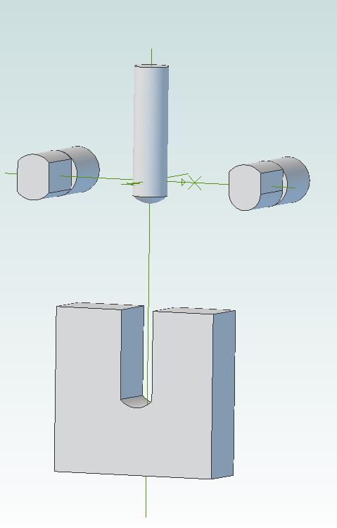
                                      slot.jpg

                                      So on the left is the rod with the flats machined on it.

                                      Piece of 12mm plate with Robin's desired 5r at the End

                                      Middle his suggested tool profile which would do the job

                                      On the Right is an option that would work leaving the 7.5dia end radius (if he can find a 7.5mm cutter) and one edge of the flat filed to match this radius, slightly less resistance to rod twisting.

                                      #340739
                                      Michael Gilligan
                                      Participant
                                        @michaelgilligan61133

                                        Thanks for the illustration, Jason

                                        It clearly demonstrates the wisdom of HOWARDT's comment.

                                        'though presumably there is/was some reason for it to be designed that way.

                                        MichaelG.

                                        .

                                        P.S. … if the proposed slot shape is required, it might be easier to broach the end detail.

                                        [ as already suggested by previous posters ]

                                        Edited By Michael Gilligan on 10/02/2018 08:12:17

                                        Edited By Michael Gilligan on 10/02/2018 08:29:10

                                        #340741
                                        JasonB
                                        Moderator
                                          @jasonb

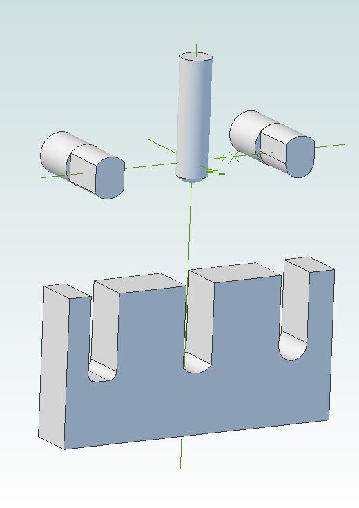
                                          Another option may be to "square off" the bottom of the slot with a LS 3mm dia cutter then the 10mm shaft dia will but up against the flat and no stress raisers in the bottom corners of the slot if that matters.

                                          slot2.jpg

                                          #340906
                                          Robin Graham
                                          Participant
                                            @robingraham42208

                                            Thanks for replies – and especially to JasonB for taking the time to make a drawing which exactly illustrates what I want to do. As to why I want to do this, which Hopper quite reasonably asks, I think the best answer I can give is that I haven't got an engineering background and learn new stuff by taking on projects beyond my experience then try to figure out a way of doing it. Sometimes that means over-engineering – I think of a solution, realise that I don't know how to implement it, and then it becomes more about 'how would I do this' than getting the job done.

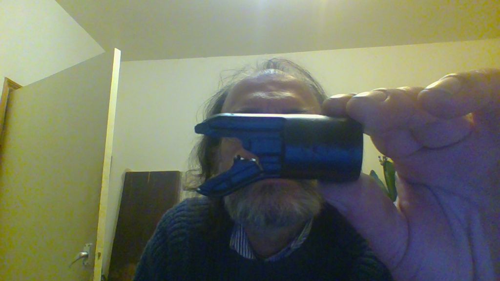
                                            The job in hand is to replace the front wheel mountings on a three wheel buggy – as Hopper suggests it probably isn't worth the candle to get an exact fit, but I'd not thought of the broaching approach so I'll probably give that a go because I've never done it before…

                                            win_20180210_22_37_13_pro.jpg

                                            #340908
                                            Hopper
                                            Participant
                                              @hopper

                                              I think instead of over-engineering the radius on the slot I would be looking at over-engineering the choice of material to something stronger, eg steel.

                                              #340915
                                              JasonB
                                              Moderator
                                                @jasonb
                                                Posted by Hopper on 11/02/2018 02:39:29:

                                                I think instead of over-engineering the radius on the slot I would be looking at over-engineering the choice of material to something stronger, eg steel.

                                                As the one in the photo looks to be plastic Robin looks to have that covere dby making an aluminium replacementsmiley

                                                #340925
                                                Michael Gilligan
                                                Participant
                                                  @michaelgilligan61133
                                                  Posted by JasonB on 11/02/2018 07:26:15:
                                                  … the one in the photo looks to be plastic

                                                  .

                                                  That would explain a lot about the slot design:

                                                  It is a simple matter to mould the shape, but machining it brings those 'design for production' issues that HOWARDT mentioned.

                                                  MichaelG.

                                                  #340932
                                                  pgk pgk
                                                  Participant
                                                    @pgkpgk17461

                                                    I'm sure there's lots of ways of achieving this but it strikes me that one of the simplest wuld be to mill out a 10mm slot to give the correct radius then mill off a bit of the side wall with a cutter down the length of the slot to give a square end to the side walls and slip a shim each side..could be bonded in or a thick enough shim to hold a thread: you've looking at at least 1.5mm each wall so going to 2mm looks possible – bond and bolt.

                                                    Or just sacrifice a 10mm round file and grind off each side and file that radius.

                                                    #340935
                                                    Hopper
                                                    Participant
                                                      @hopper
                                                      Posted by pgk pgk on 11/02/2018 09:56:52:

                                                      I'm sure there's lots of ways of achieving this but it strikes me that one of the simplest wuld be to mill out a 10mm slot to give the correct radius then mill off a bit of the side wall with a cutter down the length of the slot to give a square end to the side walls and slip a shim each side..could be bonded in or a thick enough shim to hold a thread: you've looking at at least 1.5mm each wall so going to 2mm looks possible – bond and bolt.

                                                      Or just sacrifice a 10mm round file and grind off each side and file that radius.

                                                      You'd have to use bearing blue on the shaft to make sure you filed the end of the slot exactly square to match the shaft. Then you could probably get in there with a curved three-sided scraper to finish it off, just like scraping a bearing half-shell to match a spindle.

                                                    Viewing 25 posts - 1 through 25 (of 28 total)
                                                    • Please log in to reply to this topic. Registering is free and easy using the links on the menu at the top of this page.

                                                    Advert

                                                    Latest Replies

                                                    Home Forums Beginners questions Topics

                                                    Viewing 25 topics - 1 through 25 (of 25 total)
                                                    Viewing 25 topics - 1 through 25 (of 25 total)

                                                    View full reply list.

                                                    Advert

                                                    Newsletter Sign-up