A 380 V supply from a 240 volt invertor?

Advert

A 380 V supply from a 240 volt invertor?

Home Forums Workshop Tools and Tooling A 380 V supply from a 240 volt invertor?

Viewing 24 posts - 1 through 24 (of 24 total)
  • Author
    Posts
  • #319737
    Andrew Tinsley
    Participant
      @andrewtinsley63637

      A friend of mine is looking for a 240 volt (single phase) to 380 volt 3 phase invertor. They are a touch expensive!

      Now I have a spare 240 volt (sp) to 240 volt (3p) invertor. I also have three 240 volt to 380 volt transformers. Can anyone see any objection to using one of these Txs on each of the 3 phases to give the required 380 volt three phase supply?

      It looks as though it should work, the power ratings of the invertor and Txs match. Can anyone see a problem?. If not, then my friend has a zero cost (to him) solution.

      Andrew.

      Advert
      #18678
      Andrew Tinsley
      Participant
        @andrewtinsley63637
        #319741
        Emgee
        Participant
          @emgee

          Andrew, you will have 3 380v supplies but all at the same phase angle, you will need to provide lag on one supply and lead on another to give you usable 3 phases at 120 degree spacing.

          Emgee

          #319742
          Ian Parkin
          Participant
            @ianparkin39383

            Emgee

            Why will the phases all be equal?

            #319743
            Michael Gilligan
            Participant
              @michaelgilligan61133
              Posted by Emgee on 02/10/2017 20:04:42:

              Andrew, you will have 3 380v supplies but all at the same phase angle, …

              Emgee

              .

              dont know … I don't think so, Emgee

              [quote] Now I have a spare 240 volt (sp) to 240 volt (3p) invertor. I also have three 240 volt to 380 volt transformers. Can anyone see any objection to using one of these Txs on each of the 3 phases to give the required 380 volt three phase supply? [/quote]

              MichaelG.

              #319745
              John Rudd
              Participant
                @johnrudd16576

                Theoretically it sounds doable…..the three transformer primaries connected in Delta, then the secondaries connected to give you what you need…tp or tpn…..just set the inverter for a fixed 50hz output….

                Let me know when you are going to try it so I can move to a safe location…. ( the next county perhaps…) laugh

                Should be interesting…..

                Edited By John Rudd on 02/10/2017 20:15:55

                #319746
                not done it yet
                Participant
                  @notdoneityet

                  For once, I agree with MG. After all, the inverters are much more expensive for that very reason?

                  #319747
                  John Olsen
                  Participant
                    @johnolsen79199

                    There is no particular reason for the inverter to be set on a fixed frequency. The way the inverter varies the voltage with frequency to suit a motor will be3 equally correct for the setup with the transformers in between. Actually this type of motor looks just like a transformer and load to the supply.

                    The transformers might buzz a bit with the waveforms the inverter supplies, but on the other hand the extra inductance will probably mean that the motor itself buzzes less, as it will probably see a cleaner waveform.

                    John

                    #319751
                    Andrew Tinsley
                    Participant
                      @andrewtinsley63637

                      Emgee the phases out of the 240 to 380 volt transformers will be 120 degrees out of phase, provided the 3 transformers are connected in the same way.

                      John, it also crossed my mind that the extra inductance would help clean up the waveform! VFD isn't required in this instance, so it will be strictly 50 Hertz.

                      Andrew.

                      #319754
                      Andrew Tinsley
                      Participant
                        @andrewtinsley63637

                        I forgot to mention that this is childs stuff as far as potential explosions are concerned. Take a look at the video included in the post on "how do you bend copper tubes into a 5 foot circle". That is the sort of stuff I get involved with for relaxation!

                        Take a pole transformer and feed 240 volts into the secondary. This produces 11,000v at the primary. feed this into a rotary spark gap of a big Tesla coil and sit back and see 15 foot streamers striking everywhere. Now that is when I feel I would like to be in the next county! Oh you are pulling 50 amps at 240 V when it is working well!

                        Andrew.

                        #319755
                        Emgee
                        Participant
                          @emgee

                          Andrew, I missed the fact of the supply source being from the inverter and my answer was based on a source from 240v single phase supply, not the 3 phases from the inverter.

                          Emgee

                          #319756
                          SillyOldDuffer
                          Moderator
                            @sillyoldduffer

                            This question is giving me a headache! This is what I've got so far. Please shout if it's not right!

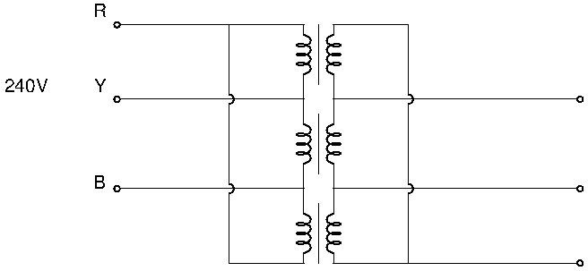
                            This circuit shows the transformers wired in delta:

                            threeph.jpg

                            On the output side I think there's a problem. The voltage across any two phases appears to be twice the secondary voltage, ie. 760V

                            Another concern is that the transformer cores may be earthed. If so the insulation will be a bit stressed.

                            I also think it's necessary to get the phases right. I reckon it goes bang if one of the transformers has its secondary connections reversed relative to the other two.

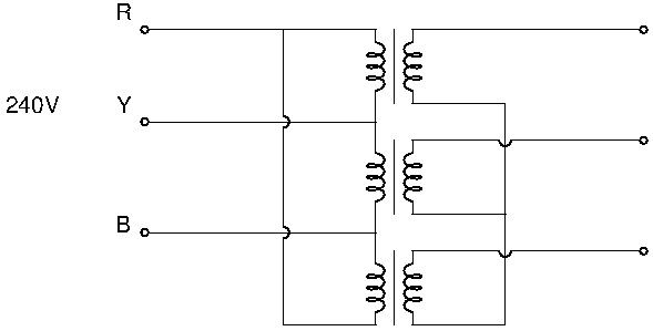
                            I believe the transformers have to be wired in a star to do what Andrew wants. But I'm not sure what voltages will appear on the output side of a star configuration. Three 380V sine waves 120 degrees apart and a centre point? My brain has exploded! Lend me an aspirin. Is there an Electrical Engineer in the house?

                            Dave

                            #319765
                            Mike Poole
                            Participant
                              @mikepoole82104

                              An inverter to supply a 400v 3 phase output will need a DC supply of around 700v this is usually created by rectifying and smoothing a three phase input. In my experience you can lose a phase and not notice until you need the full output from the inverter. If you think of the DC link as a tank that is being filled from your input supply then providing you can keep it filled when using maximum flow out then you won't have a problem. A single phase input will be unable to keep it full even if the voltage is 400v as you will have long periods when little is being put into the tank but a lot is being taken out. If the DC link voltage sags then a fault will usually be generated and shut the drive down. Using three transformers on the same phase is just the same as using one as far as filling the DC link goes.

                              Just read it again and see where you are going, three transformers of any size won't be cheap but if you have a spare drive and 3 transformers it may be worth a go, if the inverter has a sensorless flux vector mode it would probably be confused with a transformer as a load so turn it off if possible. Building a safe system out of this will need great care and it's probably best to sell the surplus hardware and buy the purpose built equipment.

                              Mike

                              Edited By Mike Poole on 02/10/2017 21:44:27

                              #319767
                              Anonymous

                                As an off the cuff statement (after a beer) I think the transformers have to be wired in delta. The output from the VFD will be 240V phase to phase, not phase to neutral, so you need the transformers in delta to get a 380V phase to phase output. The secondaries of the transformers would need to be connected in delta too, reflecting the primary connections. As Dave says a mis-connection on the secondaries could be interesting, with a lot of electrons looking for a place to go that isn't where you want them to go.

                                Andrew

                                #319773
                                SillyOldDuffer
                                Moderator
                                  @sillyoldduffer

                                  Gawd knows if this star circuit is drawn right or not. I'm out of my depth.

                                  threephstar.jpg

                                  I don't like the way the star point is in mid air.

                                  What's really confusing me is that the output depends on both phase relationships AND the transformer ratio.

                                  Like Andrew I'm going to take to alcohol. It won't help but at least I'll feel better!

                                  Dave

                                  #319775
                                  Clive Hartland
                                  Participant
                                    @clivehartland94829

                                    Is this what they call, 'A floating 3 Phase' ? If so I blew one up just trying to measure the voltage. I remember it cost nearly a £1000 to replace. It was very sensitive to mains fluctuations as that was why I was trying to monitor it.

                                    Clive

                                    #319777
                                    David Standing 1
                                    Participant
                                      @davidstanding1
                                      Posted by SillyOldDuffer on 02/10/2017 21:14:46:

                                      Is there an Electrical Engineer in the house?

                                      Dave

                                      I believe a credible source commented earlier wink 2

                                      #319787
                                      Colin Whittaker
                                      Participant
                                        @colinwhittaker20544

                                        I'd be very careful feeding a variable frequency into the output transformers. Transformers have a frequency rating to ensure they don't saturate at the rated input voltage. If you decide to lower the input frequency then you'll need to lower the input voltage (probably in a linear fashion). If the objective is to finally drive a three phase motor with a variable frequency then it is beginning to sound complicated. It may work but it needs some careful thought to minimise the risk of an expensive bang.

                                        #319792
                                        John Olsen
                                        Participant
                                          @johnolsen79199

                                          Yes, the transformers will need to be in delta on both sides, and it will be important to get them all the right way around. There is no star point, so it is not floating. The inverter does not have a star point and neither will the delta connected secondaries. I don't think that will matter, even if the load is connected star. I vaguely recall some aspects to do with unbalanced loads and harmonics being affected by connecting star to delta, but hey, that was 37 years back, and I don't think it would be important in this application.

                                          Colin, these inverters are arranged to vary the output voltage linearly with the frequency, at least from the lowest frequency up to 50Hz. Above that, the frequency keeps going up but the voltage does not. So below 50Hz the flux density in the core will be at the design level, same as if it was on the rated voltage and frequency. Above 50Hz the flux density will fall off Same occurs in a motor, which means the available torque will fall off above 50 Hz, but the available power will remain about the same. If the frequency goes too high, you will start to get lots of iron losses, but ordinary motors can typically be run up to what the bearings will stand without any problem. Since it is to be a fixed frequency, all this is moot anyway.

                                          You can do some funny things. I have a ahaper with a 460 Volt delta connected motor. That means that I can't reconnect it to get a lower voltage. I have run it two different ways, one with a step up transformer to double the 230 Volt and apply it to two connections. This works fine but does not self start, You have to kick the pulley at the right moment. In theory I would be getting maybe 2/3 of the rated power. The other way is to just connect it to an ordinary 240 Volt inverter. This means that the motor is run on half its rated voltage, but can (Inverter permitting!) draw up to its rated current. So we would get half the rated power. In practice, that seems to be plenty, if you want to take a quarter of an inch off a slab of steel in a single pass.

                                          If someone decided to test the insulation of the transformer, both between windings and from winding to frame, they would probably apply a 600 Volt Megger. They would have been designed with this in mind, so should be OK connected as above.

                                          John

                                          #319798
                                          Speedy Builder5
                                          Participant
                                            @speedybuilder5

                                            Andrew T, Can you post a link to "how do you bend copper tubes into a 5 foot circle" as I couldn't find it on this forum using the "Search for" tab.
                                            BobH

                                            #319799
                                            Peter Bell
                                            Participant
                                              @peterbell11509

                                              The commercial 240 single to 380 three phase inverters I've seen dont use transformers to increase the voltage they use a voltage doubler and the 650 to 700v dc generated from this is fed straight to the inverter HT rail where the electronics chop it into the three phases as per a normal inverter.

                                              As mike says they will also work if you lose a phase but not on full power, they will also work on rotary convertors.

                                              I use a few standard 380/400v three phase inverters fed with home made voltage doublers producing 650-700vdc and they work fine so long as the switch on surge is limited, I use a 250w bulb and 2 second delay timer to energise a contactor switching the main supply on to the doubler.

                                              Doesnt solve your problem but thats why they are expensive in my experience. Good luck with the transformers!

                                              Peter

                                              #319818
                                              Martin Kyte
                                              Participant
                                                @martinkyte99762

                                                1. I agree with Andrew and John. Primary and secondary windings need to be delta connection.

                                                2. The biggest issue I can see are the independent cores. With a motor there is a common magnetic circuit which essentially means that current variations in one phase winding is communicated to the other two via the core. If the inverter is 'dumb' and makes no comparison between the output phase currents it probably should not matter. If it does something intelligent like checking the phase angles and compensating then the system could get unstable. OK there will be some feedback via the motor core and then back through the individual transformers but this is less tightly coupled if I can put it that way. I'm not saying it won't work but if things get a little unstabe this is possibly why. Personally I would like to see a 3 phase transformer used instead of 3 singles. But hey, suck it and see.

                                                regards Martin

                                                #319864
                                                Mark Rand
                                                Participant
                                                  @markrand96270

                                                  I run my workshop from an inverter/VFD with a step up transformer on the input and a delta/star transformer on the output, all fed from the 240V single phase. Two of my machines have line-neutral for the controls, so I need the star point (which is also earthed).

                                                  #319886
                                                  John Rudd
                                                  Participant
                                                    @johnrudd16576

                                                    Posted by Martin Kyte on 03/10/2017 09:08:41:

                                                    1. I agree with Andrew and John. Primary and secondary windings need to be delta connection.

                                                    2. The biggest issue I can see are the independent cores. With a motor there is a common magnetic circuit which essentially means that current variations in one phase winding is communicated to the other two via the core.

                                                    regards Martin

                                                    Maybe if the transformers are physically clamped side by side, would be better than not….?

                                                  Viewing 24 posts - 1 through 24 (of 24 total)
                                                  • Please log in to reply to this topic. Registering is free and easy using the links on the menu at the top of this page.

                                                  Advert

                                                  Latest Replies

                                                  Viewing 25 topics - 1 through 25 (of 25 total)
                                                  Viewing 25 topics - 1 through 25 (of 25 total)

                                                  View full reply list.

                                                  Advert

                                                  Newsletter Sign-up