Reference lines for dimensions – Fusion 360
Reference lines for dimensions – Fusion 360
- This topic has 15 replies, 5 voices, and was last updated 20 August 2025 at 14:39 by
 blowlamp.
 Thanks guys, I haven’t been as clear as I should have. I can get the reference line to appear in the sketch as Jason has displayed in the post above this, it’s in the final drawing page I’m wanting it to display. I suspect that it’s not possible because it’s not needed to create the part as such, but I thought I should check.
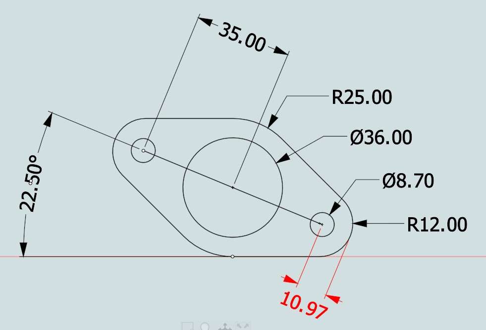
- Please log in to reply to this topic. Registering is free and easy using the links on the menu at the top of this page.
Latest Replies
-
- Topic
- Voices
- Last Post
-
-
Running 380V 3-phase motor on 230V 1-phase
1
2
Started by:
jimalm
in: Electronics in the Workshop
- 14
-
24 June 2026 at 17:52
Robert Atkinson 2
-
3D Printing in the Home Workshop
Started by:
Colin Heseltine
in: 3D Printers and 3D Printing
- 5
-
24 June 2026 at 17:29
jaCK Hobson
-
digital microscope for poor eyesight
Started by:
bernard towers
in: Electronics in the Workshop
- 14
-
24 June 2026 at 17:26
Dell
-
Letters and Parcels Box
Started by:
Michael Gilligan
in: The Tea Room
- 7
-
24 June 2026 at 17:09
Speedy Builder5
-
Rapidor 3XM
Started by:
homecat88
in: Introduce Yourself – New members start here!
- 2
-
24 June 2026 at 16:39
Nicholas Farr
-
Hot milk variations
Started by:
Gary Wooding
in: The Tea Room
- 10
-
24 June 2026 at 16:16
Andy Stopford
-
Testing Single Point Thread Fitment
Started by:
berwick
in: Beginners questions
- 13
-
24 June 2026 at 15:42
berwick
-
Emco Compact 5 milling table restoration
Started by:
rikt
in: Manual machine tools
- 5
-
24 June 2026 at 15:34
rikt
-
Moving a Chester MF42Bb(removing milling tool)
Started by:
bowmandj1953
in: Introduce Yourself – New members start here!
- 3
-
24 June 2026 at 15:27
bowmandj1953
-
Hot radiators in summer
Started by:
Gary Wooding
in: The Tea Room
- 9
-
24 June 2026 at 15:17
Neil Wyatt
-
FARM BOY Ignition
Started by:
Speedy Builder5
in: I/C Engines
- 3
-
24 June 2026 at 15:17
Speedy Builder5
-
Gas Tap Valves. Vintage
1
2
3
Started by:
dee
in: Related Hobbies including Vehicle Restoration
- 19
-
23 June 2026 at 21:24
Nigel Graham 2
-
Taylor Hobson Pantograph Engraver Model D
1
2
Started by:
jaCK Hobson
in: Workshop Tools and Tooling
- 10
-
23 June 2026 at 21:05
Charles Jambon
-
Model Turbines
1
2
…
26
27
Started by:
Turbine Guy
in: Stationary engines
- 28
-
23 June 2026 at 20:21
Turbine Guy
-
Rapidor Manchester re-build
Started by:
homecat88
in: Introduce Yourself – New members start here!
- 3
-
23 June 2026 at 19:19
homecat88
-
Advice required
Started by:
janet.ho001
in: Introduce Yourself – New members start here!
- 4
-
23 June 2026 at 19:12
janet.ho001
-
Orbital – Not your Usual Oscillator!
1
2
Started by:
JasonB
in: Stationary engines
- 14
-
23 June 2026 at 19:11
JasonB
-
Clarkson Horizontal – Redefined in Metric
Started by:
JasonB
in: Stationary engines
- 8
-
23 June 2026 at 18:48
JasonB
-
Rob Roy Build
Started by:
Dalboy
in: Locomotives
- 4
-
22 June 2026 at 21:24
Dalboy
-
Help identifying a mystery thread
Started by:
Beardy Mike
in: Beginners questions
- 8
-
22 June 2026 at 19:04
Nicholas Farr
-
Unwanted Car Software Update
Started by:
Chris Crew
in: The Tea Room
- 12
-
22 June 2026 at 16:48
paul1956
-
Oiling Lathe Ways
Started by:
Blue Heeler
in: Beginners questions
- 7
-
22 June 2026 at 13:34
Bazyle
-
Farm Boy dimensions
Started by:
Speedy Builder5
in: Stationary engines
- 3
-
22 June 2026 at 13:02
JasonB
-
Nickel Silver
Started by:
Carl
in: Materials
- 10
-
22 June 2026 at 11:52
Roderick Jenkins
-
Flame Licker Engine & USA made 1930’s Empire Water Pump
Started by:
Blue Heeler
in: Miscellaneous models
- 2
-
22 June 2026 at 10:03
Bazyle
-
Running 380V 3-phase motor on 230V 1-phase
1
2
Latest Issue

Newsletter Sign-up
Latest Replies
- Running 380V 3-phase motor on 230V 1-phase
- 3D Printing in the Home Workshop
- digital microscope for poor eyesight
- Letters and Parcels Box
- Rapidor 3XM
- Hot milk variations
- Testing Single Point Thread Fitment
- Emco Compact 5 milling table restoration
- Moving a Chester MF42Bb(removing milling tool)
- Hot radiators in summer

